Table of Contents
Advertisement
Application
The MS-IOM3723 input/output expansion module
is a part of the Metasys system Field Equipment
Controller family. Input/Output expansion modules
(IOMs) expand the number of input/output points
connected to a General Purpose Application
Controller (CGM), VAV Box Controller (CVM), SNC,
SNE, Network Automation Engine (NAE), Network
Control Engine (NCE), Advanced Application Field
Equipment Controller (FAC), Field Equipment
Controller (FEC), or Variable Air Volume Modular
Assembly (VMA) to monitor and control a wide
variety of HVAC equipment.
Note: The IOM3723 model is only available
in certain regions. Contact your local Johnson
Controls representative for more information.
IOM expansion modules operate on an RS-485
BACnet
MS/TP Bus and integrate into Johnson
®
Controls
and third-party BACnet systems. IOMs
®
Note: With Release 10.1 of the Controller
Configuration Tool (CCT), VMAs, FECs, and
FACs can be configured to communicate using
either the BACnet MS/TP or the N2 field bus
networking protocol. The operation of the
IOM is not affected by the selection of the
BACnet MS/TP or the N2 protocol in the host
controller, when the IOM is connected to the
host controller using the SA bus.
North American emissions
compliance
United States
This equipment has been tested and found to
comply with the limits for a Class A digital device
pursuant to Part 15 of the FCC Rules. These limits
are designed to provide reasonable protection
against harmful interference when this equipment
is operated in a commercial environment. This
equipment generates, uses, and can radiate radio
frequency energy and, if not installed and used in
accordance with the instruction manual, may cause
harmful interference to radio communications.
Operation of this equipment in a residential area
may cause harmful interference, in which case the
IOM3723 Input/Output Module Installation Guide
users will be required to correct the interference at
their own expense.
Canada
This Class (A) digital apparatus meets all the
requirements of the Canadian Interference-Causing
Equipment Regulations.
Cet appareil numérique de la Classe (A) respecte
toutes les exigences du Règlement sur le matériel
brouilleur du Canada.
Installation
Observe the following guidelines when installing an
expansion module:
• To minimize vibration and shock damage,
transport the expansion module in the original
container.
• Verify that all parts shipped with the expansion
module.
• Do not drop the expansion module or subject it
to physical shock.
Parts included
• One expansion module with removable
terminal blocks (Power and SA/FC bus are
removable)
• One installation instructions sheet
Materials and special tools needed
• Three fasteners appropriate for the mounting
surface (M4 screws or #8 screws)
• One 20 cm (8 in.) or longer piece of 35 mm
DIN rail and appropriate hardware for DIN rail
mount
• Small straight-blade screwdriver for securing
wires in the terminal blocks
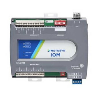
Physical features
The following figure displays the physical features
of an IOM, and the accompanying table provides a
*24101431124E*
Part No. 24-10143-1124 Rev. E
2020-10-30
(barcode for factory use only)
MS-IOM3723
Advertisement
Table of Contents

Related Manuals for Johnson Controls IOM3723


Summary of Contents for Johnson Controls IOM3723
- Page 1 Assembly (VMA) to monitor and control a wide variety of HVAC equipment. Observe the following guidelines when installing an Note: The IOM3723 model is only available expansion module: in certain regions. Contact your local Johnson • To minimize vibration and shock damage, Controls representative for more information.
- Page 2 Figure 1: IOM3723 physical features Mounting Table 1: IOM3723 features callout numbers and descriptions Observe these guidelines when mounting an IOM Callo Physical features: description and references expansion module:...
- Page 3 See the following figure for mounting dimensions listed in millimeters and inches. Inches are listed Wall mount applications in parenthesis. The following figure also illustrates the DIN rail channel and the mounting clips in an About this task: extended position. IOM3723 Input/Output Module Installation Guide...
- Page 4 For detailed information on configuring and wiring an MS/TP bus, FC bus, and SA bus, refer to the MS/TP Communications Bus Technical Bulletin (LIT-12011034). IOM3723 Input/Output Module Installation Guide...
- Page 5 Input terminal blocks The IOM3723 has inputs only (no outputs). The inputs are located on both the top and bottom of the expansion module. See Table 2 for more information about I/O terminal functions, requirements, and ratings.
- Page 6 In addition to the wiring guidelines in Table 2 • Run all low-voltage wiring and cables separate from high-voltage wiring. IOM3723 Input/Output Module Installation Guide...
- Page 7 I/O terminal blocks, ratings, and requirements Table 2: IOM3723 terminal blocks, functions, ratings, requirements, and cables Terminal block Determine wire size and Terminal label Function, ratings, requirements label maximum cable length Binary Input - Dry Contact Maintained Mode 0.01 second minimum pulse width Internal 16 V, 10K ohm pull Binary Input - Pulse Counter/Accumulator Mode 0.01 second minimum pulse width...
- Page 8 (Maximum total current draw for SA Bus is 100 mA.) 24 VAC Power Supply - Hot 0.8 mm to 1.0 mm Supplies 20–30 VAC (Nominal 24 VAC) (18 AWG) 2-wire 24 VAC Power Supply - Common IOM3723 Input/Output Module Installation Guide...
-
Page 9: Setup And Adjustments
Termination details Note: See Table 3 to determine wire size and cable lengths for cables. A set of Johnson Controls termination diagrams Note: The SA Bus and FC Bus wiring provides details for wiring inputs and outputs to the recommendations in this table are for MS/ controllers. - Page 10 Determine the physical location of the expansion module on the SA or FC bus. Determine if the expansion module must be set as a terminating device on the bus. IOM3723 Input/Output Module Installation Guide...
- Page 11 Refer to the Mobile Access Portal Gateway Catalog Page (LIT-1900869) to identify the appropriate product for (MAP) Gateway your region. TL-CCT-0 Controller Configuration Tool (CCT) Software MS-FCP-0 Field Controller Firmware Package Files for CCT TP-2420 Transformer, 120 VAC Primary to 24 VAC secondary, 20 VA, Wall Plug IOM3723 Input/Output Module Installation Guide...
- Page 12 AP-TBK4SA-0 Replacement SA Bus Terminal Blocks, 4-Position, Brown, Bulk Pack of 10 AP-TBK4FC-0 Replacement FC Bus Terminal Blocks, 4-Position, Blue, Bulk Pack of 10 AP-TBK3PW-0 Replacement Power Terminal Blocks, 3-Position, Gray, Bulk Pack of 10 IOM3723 Input/Output Module Installation Guide...
-
Page 13: Technical Specifications
The performance specifications are nominal and conform to acceptable industry standard. For application at conditions beyond these specifications, consult the local Johnson Controls office. Johnson Controls shall not be liable for damages resulting from misapplication or misuse of its products. -
Page 14: Repair Information
CHINA Contact information Contact your local branch office: www.johnsoncontrols.com/locations Contact Johnson Controls: www.johnsoncontrols.com/contact-us © 2020 Johnson Controls. All rights reserved. All specifications and other information shown were current as of document revision and are subject to change without notice. www.johnsoncontrols.com...
Need help?
Do you have a question about the IOM3723 and is the answer not in the manual?
Questions and answers