Nice Pro-H Instructions And Warnings For Installation And Use
Automation for sectional and rolling doors
Hide thumbs
Also See for Pro-H:

Related Manuals for Nice Pro-H


Summary of Contents for Nice Pro-H
- Page 1 Pro-H/J Automation for sectional and rolling doors Instructions and warnings for installation and use...
-
Page 2: Table Of Contents
SECTION B: PRO-J(M), PRO-H(M) Relay Logic Controls with Interface Module . . . . . . . . . . . . . . . -
Page 3: Warranty
Warranty NICE NORTH AMERICA warrants that materials and workmanship are free from defects for a period of four (4) years or 100,000 cycles, whichever comes first. The start of the warranty will be determined by the date of invoice. Materials returned to Nice deemed defective after examination will be returned at the option of Nice with repaired, new, or re-manufactured parts. -
Page 4: Verification Of Operator And Hardware
Verification of Operator and Hardware Upon delivery of your Nice heavy-duty jackshaft door operator, please inspect the unit carefully for damage. Verify that operator control wiring option, HP, voltage, phase and amperage correspond to available power supply and door application. Check that along with your operator you have received the following standard hardware. -
Page 5: Pro-H, Pro-J Specifications
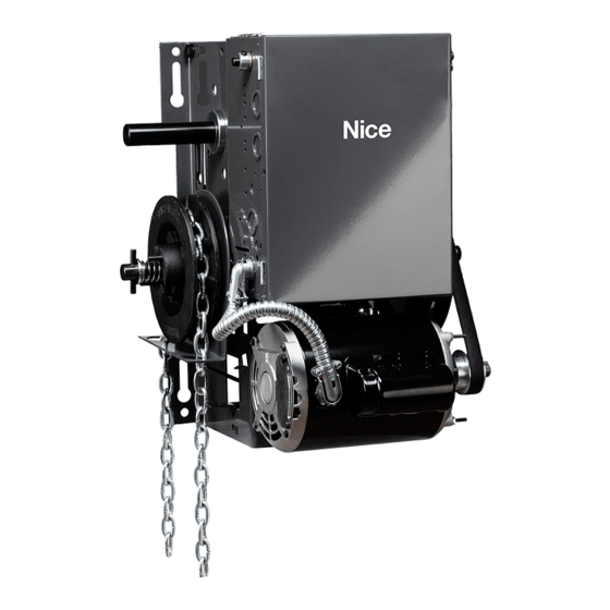
PRO-J and PRO-H heavy-duty jackshaft operators are designed for commercial and industrial high lift, vertical lift, rolling doors and rolling grilles provided that doors are driven by a drive shaft. Model PRO-H is essentially the same as model PRO-J with the exception that the PRO-H operator incorporates a chain hoist for manual operation of the door. -
Page 6: Important Safety Instructions
Important Safety Instructions WARNING: To reduce the risk of injury or death: • READ AND FOLLOW ALL INSTRUCTIONS • Never allow children to operate or play with door controls. Keep the remote control (where provided) away from children. • Personnel should keep away from a door in motion and keep the moving door in sight until it is completely closed or opened. NO ONE SHOULD CROSS THE PATH OF A MOVING DOOR. -
Page 7: Installation Instructions
• The PRO-J and PRO-H operators have dual output shafts and may be mounted on left (standard) or right hand side of door. If handing of operator must be reversed, loosen set screws, remove drive sprocket and keyway and install on opposite side of drive shaft. - Page 8 3. As a general rule, the door operator should be installed below the drive shaft and as close to the door as possible. The ideal distance between the operator drive shaft and the door shaft is approximately 12” (30cm) to 15” (38cm). The operator may be wall/bench mounted or bracket/shelf mounted.
- Page 9 10. For PRO-H models: Install hand chain by wrapping it through chain guard holes and pocket wheel. Allow chain to hang down towards floor. Cut chain and connect so that chain is 2’ to 3’ from the floor. 11. Install chain keeper to wall near hand chain at approximately 4’ from floor. Run disconnect chain through keyhole of chain keeper and cut excess chain links if required.
-
Page 10: Electrical Connections
EACH INDIVIDUAL COMMERCIAL DOOR OPERATOR MUST HAVE IT’S OWN DEDICATED POWER SUPPLY • NICE HIGHLY RECOMMENDS THAT EACH INDIVIDUAL COMMERCIAL DOOR OPERATOR HAVE AN EXTERNAL CIRCUIT BREAKER OR FUSED DISCONNECT WARNING COMPARE AVAILABLE POWER SUPPLY VOLTAGE TO OPERATOR NAMEPLATE PRIOR TO ELECTRICAL CONNECTION . -
Page 11: Section A: Pro-J, Pro-H Standard Relay Logic Controls
SECTION A: PRO-J, PRO-H Standard Relay Logic Controls (not UL325 (2010) Compliant, not available in US or Canada) Connection of Power Supply and Control Station POWER WIRING: Use 1-1/8” (2.85 cm) diameter holes for all power wiring. 1. Single phase: Connect single phase power supply to terminals L/L1 (line) and N/L2 on three-pole power terminal strip. -
Page 12: Connection Of A Reversing Edge Device And Control Accessories
Connection of a Reversing Edge Device and Control Accessories 1. Reversing Edge device (must be normally open contact): NOTE: If the door is controlled by any device or wired in such a manner that the door is not controlled by constant pressure on close then an appropriate reversing edge must be installed. -
Page 13: Section B: Pro-J(M), Pro-H(M) Relay Logic Controls With Interface Module
Operator Electrical Connections and Start-up Instructions NOTE: THIS OPERATOR COMES WITH AN INTERFACE MODULE INTEGRATED INTO THE CONTROL CIRCUIT. THE PURPOSE OF THE INTERFACE MODULE IS TO ALLOW FOR FAILSAFE MONITORING OF A NICE COMPATIBLE SAFETY DEVICE AS PER UL 325 (2010) REQUIREMENTS. - Page 14 3) Verify Motor Direction After the electrical power connections are made and push button station is connected, manually move the door to mid-position. Press Close button for several seconds and then press stop button. If door did not move in correct direction (or if limit cams not moving in correct direction towards the close limit switch) see below: Single Phase Operators: The operators leave the factory with correct motor and limit shaft direction according to standard door installations.
- Page 15 Primary monitored safety device: Nice monitored failsafe photo beams or Nice compatible monitored failsafe devices must be connected to terminals P1 and P2 if momentary close on pushbutton is required (B2 mode). If not connected, door can only be closed by constant pressure on close pushbutton.
-
Page 16: Section C: Pro-J(E): Pro-H(E) Full Feature Logic Board Smart
SECTION C: PRO-J(E): PRO-H(E) Full Feature Logic Board Smart 10.0 [UL325 (2010) Compliant] NOTE: The operator is shipped from the factory in the D1 mode setting (constant pressure open and close). The operator should remain in this mode until all connections and limit switch adjustments are completed. - Page 17 Primary monitored safety device Nice monitored failsafe photo beams or Nice compatible monitored failsafe devices must be connected to terminals P1 and P2 as primary monitored safety device. Primary monitored safety device must be connected if momentary activation on close is required in B2, T and TS modes.
-
Page 18: Connection Of External Single-Button Device
Secondary Non-Monitored Safety Device(s): A standard 2-wire safety edge, non-monitored photo beams or any other non-monitored reversing devices with a N.O contact can be connected to terminals S1 and S2 as secondary non-monitored safety device. NOTE: More than one secondary non-monitored safety device can be connected to terminals S1 and S2. IMPORTANT: Do not remove the resistor that is factory installed across terminals S1 and S2 unless installing a 4-wire electric edge. - Page 19 C2 (Momentary open, constant pressure close): • Open Button: Momentary activation opens the door. When door is closing, momentary activation reverses the door (OPEN OVERRIDE). Momentary contact from mid-stop opens the door to full open position. Constant activation when door is opening, bypass mid-stop if enabled. •...
-
Page 20: Programming Instructions
• Timer to Close: Closes the door from mid-stop or full open. Momentary activation of stop button will deactivate the timer. When door is closing, momentary activation of safety devices will reverse the door to mid-stop (if enabled) or full open and deactivates the timer. -
Page 21: Mid-Stop Setup
OFF, activation of close button will delay to POT2 amount of time. On-Board Receiver Programming This logic board has a built-in 372 MHz radio receiver and can only be used with Nice single button, 3-button (OPEN/CLOSE/STOP) and 3-channel radio transmitters. -
Page 22: Programming The On-Board Radio Receiver
(1) this device may not cause harmful interference, and (2) this device must accept any interference received, including interference that may cause undesired operation. NOTE: If an external radio-receiver (Nice or other) is used instead of the built-in radio receiver, it is highly recommended to disconnect the co-axial cable from the logic board. -
Page 23: Dip-Switch Setup
T or TS mode can be selected to enable Mid-stop Timer Timer is enabled from mid-stop only full open a timer for mid-stop Nice recommends 1.5 second delay on Delay on reverse Delay on revers is 1.5 seconds Delay on revers is 0.5 seconds revers for all applications... -
Page 24: Section D: For All Operator Control Types
SECTION D: For all Operator Control Types Limit Switch Adjustment Adjustment of door travel is done by moving the limit cams on the threaded shaft. The position of the 4 limit switches are factory adjusted and should not be altered. The limit switches are: •... -
Page 25: Section E: For Operators With Interface Modules Or Logic Boards
IMPORTANT For momentary activation on close, the Nice photobeams (or a Nice 2-wire monitored edge), must be installed as part of the operator system . If a Nice 2-wire monitored edge or the Nice infrared photobeam system is not installed (or not operating correctly), the operator will only operate in fault mode “constant pressure to close”... -
Page 26: Nice N-4 Photocell (Mk00650)
4. Connect these paired wires to the P1 and P2 terminals on the logic board (or interface module if applicable) as shown in Figure 3. FIGURE 3 NICE N-4 Photocell (MK00650) NOTE: The MK00650 photocell system has a maximum range of 24 ft. Sun Visor protector optional. Installation NOTE: Photo beams should be mounted as close to the door track inside the door to offer maximum entrapment protection. -
Page 27: For Nice Nema-1 And Nema-4 Photobeams
Photo system operation: Nice photo beams must be connected for the door to close in momentary mode (unless a Nice monitored 2-wire edge is connected). When the photo system is properly installed and aligned, the infrared beam will detect any obstruction in the path of the beam. Upon detecting an obstruction, closing door will stop and reverse to full open. -
Page 28: Fraba N-4/4 Thru-Beam Photocell (Mk00697)
FRABA N-4/4 Thru-Beam Photocell (MK00697) NOTE: The MK00687 photocell system has a maximum range of 45 ft. Sun Visor protector optional. 1. Select a location on the wall no more than 6 inches from the floor to install wall mounting brackets on the left and right side of the door. -
Page 29: Clutch Adjustment
Clutch Adjustment Installation Safety Precautions 1. Remove cotter pin tapped to pulley. 2. Rotate clutch nut counterclockwise (loosen) until there is insufficient tension to permit clutch to drive door. 3. Gradually tighten clutch nut until the tension on the Spring is sufficient to permit clutch to drive door smoothly but will allow clutch to slip if door is obstructed. -
Page 30: Emergency Manual Operation
For PRO-H operators: Operate door by pulling on hand chain. To return to electrical operation release disconnect chain and allow to return to original position. Lock hand chain in place (to Chain Keeper or Floor Level Disconnect) when not in use. -
Page 31: Operator Maintenance
Operator Maintenance WARNING TO REDUCE THE RISK OF INJURY OR DEATH: DO NOT ATTEMPT TO SERVICE THE OPERATOR UNLESS POWER SUPPLY HAS BEEN DISCONNECTED . • Inspect manual function of the door every 3-months. Make sure that door runs smoothly. If door does not manually open or close freely, have a qualified service person make repairs. -
Page 32: Jackshaft Operator Pro-J / Pro-Jb Diagram
Jackshaft Operator Pro-J / Pro-JB Diagram... -
Page 33: Jackshaft Operator Pro-J / Pro-Jb Parts List
Jackshaft Operator Pro-J / Pro-JB Parts List PRO-J PRO-JB C/W BRAKE CODE ITEM # DESCRIPTION (PRO-J/JB) QUANTITY QUANTITY MB01001 Motor 1/2HP 110/220V 1Ph BM ODP MB01102 Motor 1/2HP 208/460V 3P BM ODP MB01202 Motor 1/2HP 575V 3Ph BM ODP MB02001 Motor 3/4HP 110/220V 1Ph BM ODP MB01301 3 WIRE MOTOR 1/2HP 110V 1PH BM... - Page 34 MG00017 Flat Washer 0 .25 ID x 0 .5” OD MG00018 Lock Washer for 3/8” Screw MG00019 Flat Washer 13/16” ID x 1 .5” OD MG00020 Flat Washer 1-1/16” ID x 1-3/4” OD MG00021 Flat Washer 7/8” ID x 1-1/8” OD MG00030 Limit Cam 1/2”-20UNF MG00121...
-
Page 35: Jackshaft Operator Pro-H / Pro-Hb Diagram
Jackshaft Operator Pro-H / Pro-HB Diagram... -
Page 36: Jackshaft Operator Pro-H / Pro-Hb Parts List
Jackshaft Operator Pro-H / Pro-HB Parts List PRO-H PRO-HB C/W BRAKE CODE ITEM # DESCRIPTION (PRO-H/HB) QUANTITY QUANTITY MB01001 Motor 1/2HP 110/220V 1Ph BM ODP MB01102 Motor 1/2HP 208/460V 3P BM ODP MB01202 Motor 1/2HP 575V 3Ph BM ODP MB02001... - Page 37 MG00030 Limit Cam 1/2”-20UNF MH00001 T-Bushing 3/8” ID MH00006 Collar 3/8” ID - 3/4” OD MH00007 Collar 1” ID - 1 .5” OD MH00008 Collar 3/4” ID - 1 .25” OD MH00009 Flanged Bearing 1” ID x 2” OD MH00013 Flange Bearing 3/4”ID x 1-3/8”...
-
Page 38: Ms-100-Im-Ww 1-Phase Wiring Diagram
MS-100-IM-WW 1-Phase Wiring Diagram... -
Page 39: Msl100-110V-Ww 1-Phase Wiring Diagram
MSL100-110V-WW 1-Phase Wiring Diagram... -
Page 40: Ms300-Ww 3-Phase Wiring Diagram
MS300-WW 3-Phase Wiring Diagram... -
Page 41: Ms300-Im-Ww 3-Phase Wiring Diagram
MS300-IM-WW 3-Phase Wiring Diagram Nice Group Canada Inc 1380 St. Regis BLVD, Dorval, QC H9P 2T5... -
Page 42: Msl300-Ww 3-Phase Wiring Diagram
MSL300-WW 3-Phase Wiring Diagram... -
Page 43: Mslc300-Ww 3-Phase Wiring Diagram
MSLC300-WW 3-Phase Wiring Diagram... -
Page 44: Technical Support Hours
Customer Service 5919 Sea Otter Place, Suite 100 Technical Support Hours: Carlsbad, CA 92010 M – F, 8:00 a .m . – 6:00 p .m . ET Niceforyou .com ©2023 Nice North America LLC. All rights reserved. MN00055 Rev-A...
Need help?
Do you have a question about the Pro-H and is the answer not in the manual?
Questions and answers