Nice spido Instructions And Warnings For The Fitter
Hide thumbs
Also See for spido:
- Manual (78 pages) ,
- Instructions and warnings for installation and use (36 pages) ,
- Quick start manual (2 pages)
Table of Contents
Advertisement
Advertisement
Table of Contents

Subscribe to Our Youtube Channel
Related Manuals for Nice spido


Summary of Contents for Nice spido
- Page 1 Instructions and warnings for the fitter Istruzioni ed avvertenze per l’installatore Istructions et recommandations pour l’installateur Anweisungen und Hinweisefür den Installateur Instrucciones y advertencias para el instalador Instrukcje dla instalatora...
-
Page 2: Table Of Contents
Indice: page page Product description Programming Programming pauses Installation Programming current sensitivity Preliminary checks Programming the photo-test mode Typical system layout Electrical connections Testing 2.3.1 Electrical diagram 2.3.2 Description of connections Maintenance 2.3.3 Notes on connections Disposal 2.3.4 Photo-test... -
Page 3: Product Description
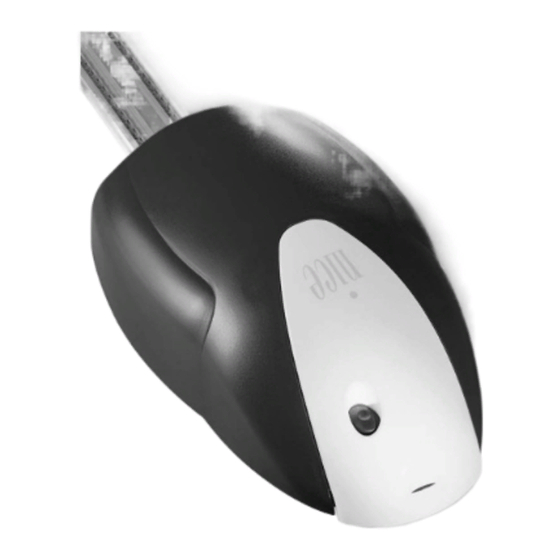
1) Product description: The control unit for the SP6000 is suitable for moving sectional doors, motor; this is done by measuring the amount of current absorbed. up-and-over doors with counterweights and up-and-over doors with This system recognises obstacles during normal movement (anti- springs;... -
Page 4: Typical System Layout
2.2) Typical system layout To clarify certain terms and aspects of a door automation system, we have included a typical example of a system for an up-and-over door. Description The description refers to the typical system shown in Fig. 2 SP6000. -
Page 5: Electrical Diagram
2.3.1) Electrical diagram RADIO LED OK 1 2 3 4 5 6 7 8 9 10 PROGRAMMING BUTTON (PROG) RAMMAZIONE (PROG) “STEP-BY-STEP” BUTTON O PASSO (PP) 2.3.2) Description of connections A brief description of the possible control unit output connections follows. Terminals Function Description... -
Page 6: Photo-Test
2.3.4) Photo-test The control unit of the SP6000 features the “Photo-test” function. All this is only possible if a special configuration of the safety device This is an excellent solution as regards the reliability of safety devices connections is used; in practice, the “TX” photocell transmitters are and puts the control unit + safety device assembly into “category 2”... -
Page 7: Pre-Set Functions
3.1) Pre-set functions The control unit of the SP6000 features some programmable functions These functions can be changed at any time by carrying out a suitable (see chapter 3) that are initially pre-set in a typical configuration which programming procedure. satisfies most automatic systems. -
Page 8: Programming The Photo-Test Mode
4.3) Programming the “Photo-test” mode To activate the “Photo-test” mode, make the connections described in paragraph 2.3.3 “Notes on Connections” (see Figs. 6a – 6b), and not the connections shown in Figs. 5a – 5b). Table “A4” Activating “Photo-test” Example Press and hold down the PROG button PROG When the OK Led remains permanently on;... -
Page 9: Maintenance
6) Maintenance: As the control unit of the SP6000 is electronic, it needs no particular maintenance. Periodically check, however, at least twice a year, that the whole system is in perfect working order as indicated in the Testing chapter. 6.1) Disposal This product is made from various types of material, some of which Some electronic components may contain polluting can be recycled (aluminium, plastic, electric wiring).
Need help?
Do you have a question about the spido and is the answer not in the manual?
Questions and answers