Advertisement
Quick Links
Advertisement

Subscribe to Our Youtube Channel
Related Manuals for Eaton Innovative Technology SPD


Summary of Contents for Eaton Innovative Technology SPD
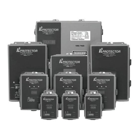
- Page 1 E E a a t t o o n n ® ® I I n n n n o o v v a a t t i i v v e e T T e e c c h h n n o o l l o o g g y y ® ® S S P P D D P P r r o o d d u u c c t t s s T T h h e e I I . . T T . . P P r r o o t t e e c c t t o o r r Installation Manual p/n: IM01005010E Revision 08...
- Page 2 All other trademarks are property of their respective companies. All other trademarks are property of their respective companies. ©Copyright 2024 Eaton, Raleigh, NC, USA. All rights reserved. No part of this document may be reproduced in any way without the express written approval of Eaton.
-
Page 3: Table Of Contents
3 3 W W a a r r r r a a n n t t y y ............................................................1 1 8 8 3.1 Warranty..............................18 Eaton Innovative Technology SPD Products The I.T. Protector Installation Manual IM01005010E—Rev 08... -
Page 4: Introduction
1 1 . . 1 1 . . 1 1 S S c c o o p p e e This installation manual contains the information necessary to install Eaton Corporation’s line of I.T. Protector Surge Protective Devices (SPDs) for the following electrical system wiring configurations: •... -
Page 5: Shock Hazards
• Use appropriate safety precautions and equipment for arc flash protection. • During normal operation, hazardous voltages are present inside the unit. Eaton Innovative Technology SPD Products The I.T. Protector Installation Manual IM01005010E—Rev 08... -
Page 6: Installation
For SPDs that are n n o o t t s s u u p p p p l l i i e e d d with wire, the customer must provide wires of the appropriate size and color as specified in Table 1 below. These wires are used to connect the SPD to the electrical system as described in 2.1.6 Disconnecting the ATN Filter. Eaton Innovative Technology SPD Products The I.T. Protector Installation Manual IM01005010E—Rev 08... - Page 7 Choose a hole location that will provide the minimum connecting wire length, while also not disturbing or damaging any components inside the SPD. Take care to capture and remove all metal shavings during the drilling process to avoid possible short circuits. Eaton Innovative Technology SPD Products The I.T. Protector Installation Manual IM01005010E—Rev 08...
- Page 8 N N O O T T E E SPD models that are light in weight can be mounted directly on the electrical panel using only a chase nipple and conduit nuts. Eaton Innovative Technology SPD Products The I.T. Protector Installation Manual IM01005010E—Rev 08...
- Page 9 (133.4) Mounting Weight: <240V PTE048, 065, 080 = 7 lb Hole >240V PTE048, 065, 080 = 12 lb PTX/PTE160 = 12 lb Dim ensions: Inches (m m ) Eaton Innovative Technology SPD Products The I.T. Protector Installation Manual IM01005010E—Rev 08...
- Page 10 F F i i g g u u r r e e 5 5 . . C C i i r r c c u u i i t t B B r r e e a a k k e e r r ( ( C C ) ) & & C C i i r r c c u u i i t t B B r r e e a a k k e e r r D D i i s s c c o o n n n n e e c c t t ( ( C C D D ) ) O O p p t t i i o o n n s s f f o o r r 4 4 8 8 , , 6 6 5 5 , , 8 8 0 0 , , 1 1 2 2 0 0 , , 1 1 6 6 0 0 2 2 4 4 0 0 o o r r 3 3 0 0 0 0 k k A A M M o o d d e e l l s s Eaton Innovative Technology SPD Products The I.T. Protector Installation Manual IM01005010E—Rev 08...
- Page 11 F F i i g g u u r r e e 6 6 . . C C i i r r c c u u i i t t B B r r e e a a k k e e r r D D i i s s c c o o n n n n e e c c t t ( ( C C a a n n d d C C D D ) ) O O p p t t i i o o n n f f o o r r 4 4 0 0 0 0 k k A A M M o o d d e e l l s s Dimensions: Inches (mm) Eaton Innovative Technology SPD Products The I.T. Protector Installation Manual IM01005010E—Rev 08...
- Page 12 6. Plate and brackets are to be painted ANSI 61 GREY. 7. Bracket is to be bent at dashed lines, according to dimensions in the 0.65 1.25 5.25 1.25 illustration. Eaton Innovative Technology SPD Products The I.T. Protector Installation Manual IM01005010E—Rev 08...
- Page 13 Next to the Circuit Breaker mounting panel, locate a green/yellow loop of wire. Use a wire-cutting tool to cut this wire in the center of the loop. Cap off the ends of each wire using UL listed wire nuts. Close or reinstall cover. Eaton Innovative Technology SPD Products The I.T. Protector Installation Manual IM01005010E—Rev 08...
- Page 14 N N e e u u t t r r a a l l C C o o n n n n e e c c t t i i o o n n – Connect the SPD’s Neutral (WHT) wire directly to the electrical panel’s Neutral bus bar. Eaton Innovative Technology SPD Products The I.T. Protector Installation Manual IM01005010E—Rev 08...
- Page 15 2.1.3 Overcurrent Protective Device Requirement)* to the electrical panel’s Phase A voltage bus bar. Repeat Step c to connect the SPD’s Phase B (BLK) wire to its associated bus bar. Eaton Innovative Technology SPD Products The I.T. Protector Installation Manual IM01005010E—Rev 08...
- Page 16 Requirement)* to the electrical panel’s Phase A voltage bus bar. Repeat Step c. to connect the SPD’s Phase B and C (BLK) wires to their associated bus bars. Eaton Innovative Technology SPD Products The I.T. Protector Installation Manual IM01005010E—Rev 08...
- Page 17 For Circuit Breaker or Circuit Breaker Disconnect SPD models (with a “C” or “CD” suffix), connect the SPD wires to the electrical panel according to National, State, and Local codes. Eaton Innovative Technology SPD Products The I.T. Protector Installation Manual IM01005010E—Rev 08...
-
Page 18: 2.1.7 Wiring Spd To Electrical System
By connecting a remote alarm to these contacts, the alarm can be made to activate when the relay de-energizes as the result of losing at least one phase voltage. Eaton Innovative Technology SPD Products The I.T. Protector Installation Manual IM01005010E—Rev 08... - Page 19 10, the Form C relay will de-energize if one of the Phase voltages is lost, causing the alarm to activate. Recheck all connections, and then close or reinstall cover. Eaton Innovative Technology SPD Products The I.T. Protector Installation Manual IM01005010E—Rev 08...
- Page 20 SPD’s operational status. • With all phase voltages present, the Form C relay should energize causing its contacts to move to their normal position. Eaton Innovative Technology SPD Products The I.T. Protector Installation Manual IM01005010E—Rev 08...
-
Page 21: Disclaimer Of Warranties And Limitation Of Liability
W W a a r r r r a a n n t t y y Eaton warrants these products for a period of 5 years from the date of delivery to the purchaser, 20 years if the product is properly registered with Eaton, to be free from defects in both workmanship and materials. To register visit www.eaton.com/itvss and click the warranty registration icon. -
Page 22: Warranty
Eaton Innovative Technology SPD Products The I.T. Protector Installation Manual IM01005010E—Rev 08... - Page 23 IM01005010E08 IM01005010E 08...
Need help?
Do you have a question about the Innovative Technology SPD and is the answer not in the manual?
Questions and answers