Table of Contents
Advertisement
Quick Links
P P M15000i i
Operator Manual
PORTABLE INVERTER GENERATOR
IMPORTANT – Please make sure everyone who will be using this equipment reads and understands
these instructions as well as any additional instructions provided before using it.
Record the model and serial numbers of your Generator below:
Model No.
Serial No.
Advertisement
Table of Contents

Related Manuals for Promate PM15000i


Summary of Contents for Promate PM15000i
- Page 1 P P M15000i i Operator Manual PORTABLE INVERTER GENERATOR IMPORTANT – Please make sure everyone who will be using this equipment reads and understands these instructions as well as any additional instructions provided before using it. Record the model and serial numbers of your Generator below: Model No.
-
Page 2: Table Of Contents
FOREWORD Thank you for purchasing Promate PM15000i. This operator manual is for proper handling, minor checking, and maintenance of the PM15000i. Before using your generator: Please read these instructions completely and carefully to operate it safely and make the best use of it. Due to constant efforts to improve our products, certain procedures and specifications are subject to change without notice, if you have any questions, please contact Promate Service. - Page 3 Multi Switch on OFF……………………………………………………………………………………… Draining the Oil…………………………………………………………………………………………… Removing Both Maintenance Covers……………………………………………………………… Air Filter Location………………………………………………………………………………………… Spark Plug Location………………………………………………………………………………………. Spark Plug Gap Guide…………………………………………………………………………………… Cleaning the Spark Arrestor…………………………………………………………………………… PM15000i Exploded View………………………………………………………………………………. Table Title Page General Specifications…………………………………………………………………………………… Generator Maintenance Schedule…………………………………………………………………… Valve Clearance Maintenance Schedule…………………………………………………………….
-
Page 4: Safety Precautions
1. SAFETY PRECAUTIONS This manual provides safety information for Promate PM15000i, including preparation, operation, and maintenance instructions. Before running this generator, please read and observe all warnings and instructions that are provided both on the generator labels and in this instruction manual. Failure to follow the guidelines below may cause personal injury. -
Page 5: Controls And Features
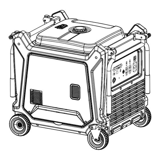
2. CONTROLS AND FEATURES Read this owner's manual before operating your generator. Familiarize yourself with the location and function of the controls and features. Save this manual for future reference. PM15000i Diagram 1. Generator Parts... -
Page 6: Control Panel Features
Control Panel Features Read this owner's manual before operating your generator. Familiarize yourself with the location and function of the controls and features. Save this manual for future reference. Diagram 2. Control Panel Features LCD Multi-Meter AC 230V – 20A Eco Mode Switch Grounding Terminal 5V USB/Type A/C... -
Page 7: Lcd Multi-Meter Functions
LCD Multi-Meter Functions Diagram 3. LCD Multi-Meter Functions Output Indicator (Green) Frequency (Hertz) The green light indicates that the generator is This icon shows frequency. turned on. Overload Alarm (Red) Voltage When the load exceeds the generator's overload This icon shows the voltage. value, this button flashes, and the output is automatically turned off. -
Page 8: Specifications
Gross Weight 210kg The Promate PM15000i is designed and rated for continuous operation at ambient temperatures of up to 40°C. If needed, this product can be operated at temperatures ranging from 15°C - 50°C for short periods. If the product is exposed to temperatures outside of this range during storage, it should be brought back within this range before operation. -
Page 9: Before Starting
4. Reinstall the oil dipstick and firmly tighten it. Wipe and clean any spilled oil. Promate PM15000i is equipped with low oil shut- 5. Reinstall the left maintenance cover and off and will stop when the oil level in the tighten its screw at the side to secure it. -
Page 10: Add/Check The Fuel
TIP: DO NOT fill the fuel tank to the very top. If you do, gasoline will expand and spill while in use, even with the fuel lid on. Do not overfill the tank. Allow space for fuel expansion. If fuel spills wait until it evaporates before starting the engine. -
Page 11: Connect The Battery
(milk of magnesia or vegetable oil). alternate main installation The Promate PM15000i is shipped with the instructions. battery’s negative (-) terminal disconnected to maximize safety. To start the generator using an electric start, the battery must be connected. -
Page 12: Ground The Generator
5. OPERATION damage. To operate at lower elevations, the supplied standard main jet must be utilized. Generator Location Operating the engine with the wrong main jet may result in increased exhaust emissions, fuel Review each warning to prevent fire hazards. consumption, and reduced performance. -
Page 13: Start The Generator
Diagram 18. Engine Start/Stop Button 7. Press the Engine Start/Stop Button for 5 seconds to START. (Diagram 18) Promate PM15000i is equipped with an ECO MODE Button (Diagram 15). Engaging this switch allows the system to regulate the engine speed and automatically adjust its fuel consumption to Diagram 14. -
Page 14: Stop The Generator
Storage section for proper engine and fuel storage. Low Oil Shutdown Promate PM15000i is equipped with low oil Diagram 19. Connecting Electrical Loads shutdown. If the oil level becomes lower than the minimum, the sensor will activate a warning device or stop the engine. -
Page 15: Generator Maintenance
To extend the life of your generator and 3. Plug in and turn on the first item. It is best to attach the item with the largest load first. connected devices, perform the following steps 4. Allow the engine to stabilize. on adding electrical load: 5. -
Page 16: Change The Oil
Change the Oil Check/Clean the Air Filter TIP: To avoid possible oil spills from the Check every 50 hours of operation on the carburetor bowl, drain the carburetor before Preventive Maintenance Schedule. (Table 2). draining the oil. (See pg. 15, 6.8 Drain the Routine maintenance of the air filter helps maintain Carburetor) proper airflow to the carburetor. -
Page 17: Check/Replace The Spark Plug
1. Loosen the screws at the side of the right maintenance cover and set aside. Check The Valve Clearance (Table 3) Please contact Promate Service for assistance. Proper valve clearance is essential in prolonging the life of the engine. Check the valve clearance per the Preventive Maintenance Schedule. -
Page 18: Drain The Fuel Tank
TIP: Promate PM15000i is equipped with a spark 4. Retighten the drain screw securely. arrestor that has been evaluated by the fire 5. Turn the Multi Switch to the OFF position. - Page 19 1. Turn the Multi Switch to the OFF position. Adding a Fuel Stabilizer 2. Place the generator in a leveled place to reduce If you are storing gasoline in a suitable container the possibility of fuel leakage. for later use, make sure the gasoline has been 3.
-
Page 20: Troubleshooting
3. GFCI system is activated. 3. Reset the GFCI. 4. Try plugging in a different item. If the problem 4. The item plugged in is defective. continues, contact Promate Service. If the problem persists after trying the above solutions, contact Promate Service for assistance. -
Page 21: Limited Warranty
The Company will not pay for repairs or To order replacement parts and consumable parts, adjustments to the product, or for any costs please contact Promate Service and be ready with of labor performed without the Company's the following information: prior authorization. -
Page 22: Exploded Diagram & Part List
(DAVAO) Space 10 & 11 Jin-Long Complex R. Castillo St. Agdao District, Davao City 800... -
Page 23: Pm15000I Parts List
EXPLODED VIEW AND PARTS LIST Diagram 28. PM15000i Exploded View... - Page 24 Table 6. PM15000i Parts List PART NO. DESCRIPTION QUANTITY 30101-00341-00 Hex Bolt 33126-00022-00 Plug 33013-00555-00 Upper Cover 30111-00064-00 Cross Pan-Head Screw 33048-00581-00 Sealing Strip 30101-00407-00 Hex Bolt 30136-00112-00 Washer 20130-00654-09 Fuel Tank 34037-00003-00 Filter Net 34024-00004-00 Mental Clip 33015-00251-00 Oil Radiator Outlet Sealing Strip...
- Page 25 20134-00355-00 Wheel 30136-00115-00 Washer 30117-00063-00 Cross Pan-Head Screw 30101-00339-00 Hex Bolt 33089-00540-00 Brake Install Board 20249-00915-00 Support Part 33015-00234-00 Engine Inlet Rubber Sleeve 31023-00061-00 Voltage Stabilizer 33013-00910-00 Inverter Box 30101-00412-00 Hex Bolt 20114-08492-00 Control Panel 20136-01019-00 Inverter 30101-00361-00 Hex Bolt 33013-00558-00 Panel Side Board 33015-00142-00...
- Page 26 30125-00026-00 Hex Nut 20260-06659-00 Engine 33089-00613-00 Muffler Box Cover 33089-00612-00 Muffler Fixed Board 33089-00623-00 Muffler Fixed Board Install Lug 33089-00611-00 Muffler Fixed Board Install Lug 30101-00066-00 Hex Bolt 33089-00603-00 Engine Cover 33191-00176-00 Alternator Cover 30101-00495-00 Hex Bolt 30101-00549-00 Hex Bolt 34006-00006-00 Locating Pin 33015-00253-00...
Need help?
Do you have a question about the PM15000i and is the answer not in the manual?
Questions and answers