Table of Contents
Advertisement
Quick Links
Operator Manual
PORTABLE INVERTER GENERATOR
IMPORTANT – Please make sure everyone who will be using this equipment reads and
understands these instructions as well as any additional instructions provided before using
it.
Record the model and serial numbers of your Generator below:
Model No.
Serial No.
Advertisement
Table of Contents

Subscribe to Our Youtube Channel
Related Manuals for Promate PM10000i


Summary of Contents for Promate PM10000i
- Page 1 Operator Manual PORTABLE INVERTER GENERATOR IMPORTANT – Please make sure everyone who will be using this equipment reads and understands these instructions as well as any additional instructions provided before using Record the model and serial numbers of your Generator below: Model No.
-
Page 2: Table Of Contents
FOREWORD Thank you for purchasing Promate PM10000i. This operator manual is for proper handling, minor checking and maintenance of the PM10000i. Before using your generator: Please read these instructions completely and carefully in order to operate it safely and make the best use of it. Due... - Page 3 Diagram Title Page Generator Parts…………………………………………………………………………………………… Control Panel Features…………………………………………………………………………………. Display Function………………………………………………………………………………………….. Removing the Maintenance Cover ………………………………………………………………… Adding Oil Using an Oil Funnel …………………………………………………………………… Checking the Engine Oil ………………….…………………………………………………………… Recommended Temperature for Operation …………………………………………………… Oil Dipstick Parts ………………………………………………………………………………………… Fuel Cap Location ……………………………………………………………………………………… Removing the Access Cover …………………………………………………………………………...
-
Page 4: Safety Precautions
1. SAFETY PRECAUTIONS This manual provides safety information for Promate PM10000i, including preparation, operation, and maintenance instructions. Before running this generator, please read and observe all warnings and instructions that are provided both on the generator labels and in this instruction manual. Failure to follow the guidelines below may cause personal injury. -
Page 5: Control Features
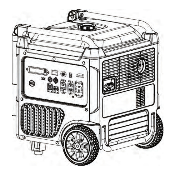
2. CONTROLS AND FEATURES Read this owner's manual before operating your generator. Familiarize yourself with the location and function of the controls and features. Save this manual for future reference. PM10000i Diagram 1. Generator Parts Fuel Cap Recoil Starter Carrying Handle... -
Page 6: Control Panel Features
2.1 Control Panel Features Control Panel Features Diagram 2. Control Panel Features LCD Multi-Meter Eco Mode Circuit Protector 9A AC 115V/230V– 50A DC 12V AC 230V – 20A Engine Switch Circuit Breaker 20A 5V USB/Type A/C Circuit Breaker 36A Engine Start/Stop Button Fuel Knob Switch... -
Page 7: Lcd Multi-Meter Function
2.2 LCD Multi-meter Function Diagram 3. Display Function Output Indicator (GREEN) Gasoline Fuel Meter The green light indicates that the generator is turned on This icon indicates the amount of fuel in the fuel tank. Overload Alarm (RED) Hours When the engine oil level is lower than the alarm value, the This icon shows the running time. -
Page 8: Specifications
3. SPECIFICATIONS Table 1. General Specifications PM10000i Model Surge Power 10000W Rated Power 8200W Rated AC Voltage Rated AC Current Rated Frequency Phase 4-stroke, OHV, Single Cylinder with Forced Air- Engine Type Cooling System Engine Displacement 459 CC OHV Starting System... -
Page 9: Before Starting
The Promate PM10000i is designed and rated for continuous operation at ambient temperatures of up to 40°C. If needed, this product can be operated at temperatures ranging from 15°C - 50°C for short periods. If the product is exposed to temperatures outside of this range during storage, it should be brought back within this range before operation. -
Page 10: Recommended Temperature For Operation
For subsequent operation, the oil level should be checked before each use, or after every 8 hours of •Never use an oil/petrol mixture. operation. Promate PM10000i is equipped with low- oil sensor and will NOT start without sufficient •Never use old petrol. -
Page 11: Connect The Battery
Connect the Battery cover. If you do not plan to use the generator for a long To ensure maximum safety, Promate PM10000i is period of time, we recommend to DISCONNECT shipped with the battery's negative (-) terminal the negative battery cable from the battery to disconnected. -
Page 12: Operation On High Altitude
Diagram 13: Manual Start Meters) 1. Turn the knob switch to “ON”. The fuel system on Promate PM10000i may be 2. Press the ENGINE SWITCH “ON”. affected by operation at high altitudes. At elevations above 2438 meters, the generator may experience a decrease in performance, even with the proper altitude kit. -
Page 13: Maintenance And Storage
Proper routine maintenance of the generator can help extend its life. Please follow the Maintenance Schedule for all maintenance checks and activities. If you have any questions concerning the maintenance procedures detailed in this manual, please contact your Promate Service. Table 2: Generator Maintenance Schedule... -
Page 14: Air Filter Maintenance
IMPORTANT GENERATOR MAINTENANCE TIPS: Drain your carburetor after use and before storage to prevent clogging. • Generator fuel should not be stored for more than 2 months to avoid spoiling. • Run the generator for at least 20 minutes every month to charge the battery and extend its life. •... -
Page 15: Valve Clearance Maintenance
Only operate the unit on a flat, level surface and in a clean, dry operating environment. Please contact Promate Service for assistance. Proper valve clearance is essential for prolonging DO NOT expose the unit to extreme conditions, the life of the generator. -
Page 16: Fuel Tank And Carburetor Maintenance
not feasible, please see the short-term and long- 1. With the help of another person, place the generator on an elevated platform such as a term storage options. table or desk. Table 4: Short-Term and Long-Term 2. Unscrew the maintenance cover knob, and Storage Options remove the cover from the side panel. -
Page 17: Transporting And Product Disposal
7. TRANSPORTING AND PRODUCT DISPOSAL To avoid possible oil spills from the carburetor bowl, drain the carburetor before draining oil. Transporting the Generator 1. Unscrew the oil access cover knob, and remove the cover from the side panel. To prevent fuel spillage when transporting, be sure to perform the following: 1. -
Page 18: Troubleshooting
Tripped AC Circuit protector(s). Check the AC load and reset the AC circuit protector(s). GFCI system activated. Reset the GFCI. Defective item plug. Try a different item or contact Promate Service. *If problem persists after trying the above solutions, Promate Service for assistance. -
Page 19: Service Information
The Company will not pay for repairs or To order replacement parts and consumable parts, adjustments to the product, or for any costs of please contact Promate Service and be ready with labor performed without the Company's prior the following information: authorization. -
Page 20: Exploded Diagram & Part List
10. EXPLODED DIAGRAM AND PART LIST Model: PM10000i Diagram 22: Promate PM10000i Exploded Diagram... -
Page 21: Generator Part List
PART LIST Table. 6 Generator Part List (Part 1) Part Number Description Qty. 20260-10459-00 ENGINE 33015-00288-00 AIR FILTER INLET RUBBER SLEEVE 30125-00026-00 HEX NUT 30125-00023-00 HEX NUT 33088-01096-00 ENGINE BASE BOARD, RIGHT ENGINE BASE BOARD, LEFT 33088-01095-00 30101-00369-00 HEX BOLT HEX BOLT 30101-00492-00 34030-00291-00... - Page 22 Table 6. Generator Part List (Part 2) Part Number Part Name Qty. 33004-01651-00 FIXED COVER, LEFT 30116-00045-00 CROSS RECESSED SCREW 33004-01790-00 HANDLE BLOCK PAD, LEFT 33580-00079-00 HANDLE LOCATING PIN 30111-00088-00 CROSS PAN-HEAD SCREW 34015-00154-00 SPRING 33580-00080-00 HANDLE LOCATING PIN 33004-01652-00 FIXED COVER, RIGHT 33004-01789-00 HANDLE BLOCK PAD, RIGHT...
Need help?
Do you have a question about the PM10000i and is the answer not in the manual?
Questions and answers