Table of Contents
Advertisement
Quick Links
Operator Manual
PORTABLE INVERTER GENERATOR
IMPORTANT – Please make sure everyone who will be using this equipment reads and understands
these instructions as well as any additional instructions provided before using it.
Record the model and serial numbers of your Generator below:
Model No._____________________ Serial No._______________________
Advertisement
Table of Contents

Related Manuals for Promate PM6800i


Summary of Contents for Promate PM6800i
- Page 1 Operator Manual PORTABLE INVERTER GENERATOR IMPORTANT – Please make sure everyone who will be using this equipment reads and understands these instructions as well as any additional instructions provided before using it. Record the model and serial numbers of your Generator below: Model No._____________________ Serial No._______________________...
-
Page 2: Table Of Contents
FOREWORD Thank you for purchasing Promate PM6800i. This operator manual is for proper handling, minor checking, and maintenance of the PM6800i. Before using your generator: Please read these instructions completely and carefully to operate it safely and make the best use of it. Due to constant efforts to improve our products, certain procedures and specifications are subject to change without notice, if you have any questions, please contact Promate Service. - Page 3 Diagram Title Page Generator Parts……………………………………………………………………………………………. Control Panel Features…………………………………………………………………………………… LCD Multi-Meter Functions…………………………………………………………………………….. Recommended Engine Oil Type………………………………………………………………………. Removing the Oil Access Cover………………………………………………………………………. Pouring Oil…………………………………………………………………………………………………… Oil Limit Guide…………………………………………………………………………………………….. Fuel Cap Location…………………………………………………………………………………………. Connect the Battery………………………………………………………………………………………. Grounding Nut……………………………………………………………………………………………… Outside Operation…………………………………………………………………………………………. Disconnecting Electrical Loads………………………………………………………………………… Low Idle Mode Switch……………………………………………………………………………………. Fuel Knob Switch on RUN……………………………………………………………………………….
-
Page 4: Safety Precautions
1. SAFETY PRECAUTIONS This manual provides safety information for Promate PM6800i, including preparation, operation, and maintenance instructions. Before running this generator, please read and observe all warnings and instructions that are provided both on the generator labels and in this instruction manual. Failure to follow the guidelines below may cause personal injury. -
Page 5: Controls And Features
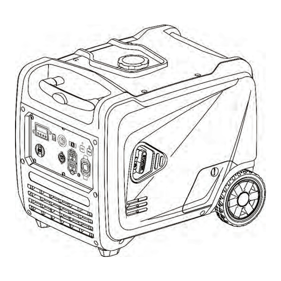
2. CONTROLS AND FEATURES Read this owner's manual before operating your generator. Familiarize yourself with the location and function of the controls and features. Save this manual for future reference. PM6800i Diagram 1. Generator Parts Fuel Cap Wheel Carrying Handle... -
Page 6: Lcd Multi-Meter Functions
2.2 LCD Multi-Meter Functions Diagram 3. LCD Multi-Meter Functions Low Idle/Eco Mode Button Running Time When the generator is in energy-saving mode, this This icon shows the running button lights up. When you turn off the energy- time. saving mode, the light will turn off. Oil Warning Indicator (Red) Hertz Icon When the engine oil level is lower than the alarm... -
Page 7: Specifications
Net Weight 57.5kg The Promate PM6800i is designed and rated for continuous operation at ambient temperatures of up to 40°C. If needed, this product can be operated at temperatures ranging from 15°C - 50°C for short periods. If the product is exposed to temperatures outside of this range during storage, it should be brought back within this range before operation. -
Page 8: Before Starting
The Promate PM6800i is designed and rated for continuous operation at ambient temperatures of up to 40°C. If needed, this product can be operated at temperatures ranging from 15°C - 50°C for short periods. If the product is exposed to temperatures outside of this range during storage, it should be brought back within this range before operation. -
Page 9: Adding Fuel
DO NOT use E85 or E15. For high altitude use, see "Operation at High Altitude". DO NOT mix oil with gasoline. DO NOT change the engine to run on other fuels. During storage, it is important to prevent gum Diagram 7. Oil Limit Guide deposits in the fuel system components such as the carburetor, fuel hose, or tank. -
Page 10: Operation At High Altitude
The Promate PM6800i is shipped with the battery’s negative (-) terminal disconnected to maximize safety. To start the generator using an Using an alternative main jet at elevations below electric start, the battery must be connected. -
Page 11: Connecting To A Building's Electrical System
federal or state regulations, municipal statutes, or DO NOT block the air vents with paper or other material. ordinances governing the generator's intended usage. Consult a qualified electrician, an electrical Surge Protection inspector, or the municipal authority with Electronic devices, such as computers and many jurisdiction. -
Page 12: Manual/Recoil Start
(the first five hours Promate PM6800i is equipped with a LOW operations). IDLE/ECO MODE Button (Diagram 13). Engaging this switch allows the system to regulate the 1. Let the engine stabilize and warm up for a few engine speed and automatically adjust its fuel minutes after starting. -
Page 13: Stopping The Generator
Storage section for proper engine and fuel storage. Low Oil Shutdown Promate PM6800i is equipped with low oil shutdown. If the oil level becomes lower than the minimum, the sensor will activate a warning device or stop the engine. If the generator shuts off and the oil level is within specifications, check Diagram 19. -
Page 14: Parallel Connection
3. Plug in and turn on the first item. It is best to attach the item with the largest load first. 4. Allow the engine to stabilize. 5. Plug in and turn on the next item. 6. Allow the engine to stabilize. 7. -
Page 15: Maintenance And Storage
8 hours of operation. Replace Spark Plug Inspect/Adjust Valve Clearance* To check (Diagram 7): * To be performed by Promate Service. 1. Place the generator on a level surface and let the engine cool for a few minutes. TIP:... -
Page 16: Spark Plug Maintenance
4. Remove the oil dipstick. the. gap, carefully bend the ground (top) electrode (only if necessary). 5. Wipe the dipstick clean, then insert it into To lessen gap, gently tap the ground the filler neck. Remove the dipstick and electrode on a hard surface (Diagram 26). check that the oil level is within a safe 6. -
Page 17: Air Filter Maintenance
TIP: Regularly check that the air cleaner is free of Promate PM6800i is equipped with a spark excessive dirt. arrestor that has been evaluated by the fire To inspect and clean the air filter: (Diagram 27) prevention regulations. -
Page 18: Generator Maintenance
Important: Please contact Promate Service for circulate the stabilizer throughout the fuel system. assistance. Proper valve clearance is essential in 3. Allow the generator to cool for a minimum prolonging the life of the engine. Check the valve of 30 minutes and then drain the fuel tank. -
Page 19: Carburetor Location
Diagram 33. Oil Drain Location Diagram 31. Carburetor Location 3. Place a suitable container underneath the generator to catch the used oil. 4. Reach under the generator and remove the black rubber seal located below the oil drain plug. Diagram 32. Draining the Fuel Tank/ Carburetor Diagram 34. -
Page 20: Troubleshooting
10. Flooded 10. Wait 5 minutes and re-crank engine. 11. Excessively rich fuel mixture. 11. Contact Promate Service. 12. Intake valve stuck open or closed. 12. Contact Promate Service. 13. Engine has lost compression. 13. Contact Promate Service. -
Page 21: Service Information
The Company will not pay for repairs or To order replacement parts and consumable parts, adjustments to the product, or for any costs please contact Promate Service and be ready with of labor performed without the Company's the following information: prior authorization. -
Page 22: Exploded Diagram & Part List
11. EXPLODED VIEW AND PARTS LIST Table 5. Engine 1 PART NO. DESCRIPTION QUANTITY 34006-00080-00 Locating Pin 33048-00510-00 Cylinder Head Gasket 34013-00124-00 Intake Valves 34013-00125-00 Exhaust Valve 20023-00229-00 Cylinder Head Assembly 34015-00111-00 Valve Springs 34018-00005-00 Inlet Valve Oil Shield 34016-00105-00 Valve Spring Seat 34016-00106-00 Valve Lock Clip... -
Page 23: Engine 2
Table 6. Engine 2 PART NO. DESCRIPTION QUANTITY 30110-00190-00 Stud Bolts 34021-00331-00 Cabinet Side Air Shroud 30117-00057-00 Cross Slot Disc Head Self-Tapping Screws 30125-00002-00 Hex Flange Face Nut 20026-00067-00 Dipstick 30117-00057-00 Cross Slot Disc Head Self-Tapping Screws 20196-02573-00 Battery Cable/Frequency Fast Plug 20196-03232-00 Connecting Wires/Grounding Wires 20196-02868-00... -
Page 24: Engine 3
Table 7. Engine 3 PART NO. DESCRIPTION QUANTITY 34008-00020-00 Tappet 20011-00311-00 Crankshaft 20011-00311-00 Crankshaft 30141-00121-00 Deep Groove Ball Bearings 20012-00087-00 Camshaft 34006-00001-00 Locating Pin 33048-00515-00 Crankcase Cover Seal Gasket 34007-00028-00 Oil Seal 30141-00121-00 Deep Groove Ball Bearings 33129-00103-00 Crankcase Cover 30101-00370-00 Hex Flange Face Bolts Table 8. -
Page 25: Engine 5
Table 9. Engine 5 PART NO. DESCRIPTION QUANTITY 34021-00284-00 Guide Wind Cover, Back Fan 30101-00662-00 Hex Flange Face Bolts 33155-00163-00 30101-00490-00 Hex Flange Face Bolts 33171-00046-00 Cover Of Back Fan 30117-00057-00 Cross Slot Disc Head Self-Tapping Screws 30110-00027-00 Exhaust Stud Bolts 33048-00571-00 Muffler Gasket 20202-00670-00... -
Page 26: Engine 7
Table 11. Engine 7 PART NO. DESCRIPTION QUANTITY 30110-00017-00 Intake Stud Bolts 33048-00512-00 Air Inlet Gasket 34012-00053-00 Carburetor Connection Block 33048-00513-00 Carburetor Gasket 1 33048-00766-00 Carburetor Gasket 2 20024-00477-00 Carburetor 34023-00386-00 Fuel Pipe 34024-00031-00 Clamps 33015-00100-00 Protective Sleeve Table 12. Engine 8 PART NO. -
Page 27: Engine 9
Table 13. Engine 9 PART NO. DESCRIPTION QUANTITY 20005-00290-00 Stator 30101-00694-00 Hex Flange Face Bolts 33593-00442-00 Crimping Plates 30101-00070-00 Hex Flange Face Bolts 20006-00170-00 Rotor 30125-00065-00 Hex Flange Face Nut 20028-00108-00 Trigger 30101-00070-00 Hex Flange Face Bolts Table 14. Engine 10 PART NO.
Need help?
Do you have a question about the PM6800i and is the answer not in the manual?
Questions and answers