Table of Contents
Advertisement
SERVICE MANUAL
(DOMESTIC & INTERNATIONAL)
IMPINGER CONVEYOR OVENS
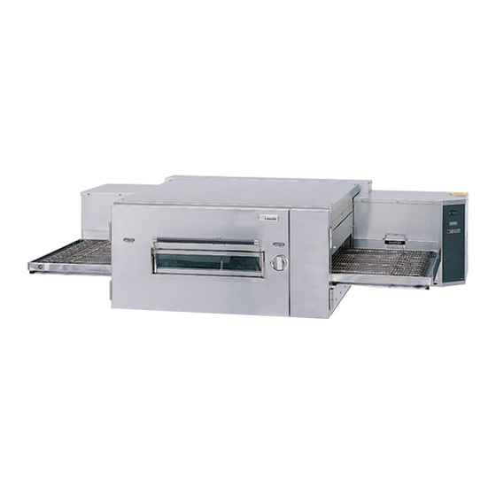
LOW PROFILE - 1600 SERIES
Lincoln Foodservice Products, Inc.
1111 North Hadley Road
P.O. Box 1229
Fort Wayne, Indiana 46801-1229
Phone: (800) 374-3004 • Fax: (260) 436-0735
Technical Service Hot Line
(800) 678-9511
www.lincolnfp.com
1600SvcMan
REV: 12/13/05
Advertisement
Table of Contents
Troubleshooting

Related Manuals for Lincoln 1600


Summary of Contents for Lincoln 1600
- Page 1 SERVICE MANUAL (DOMESTIC & INTERNATIONAL) IMPINGER CONVEYOR OVENS LOW PROFILE - 1600 SERIES Lincoln Foodservice Products, Inc. 1111 North Hadley Road P.O. Box 1229 Fort Wayne, Indiana 46801-1229 Phone: (800) 374-3004 • Fax: (260) 436-0735 Technical Service Hot Line (800) 678-9511 www.lincolnfp.com...
-
Page 2: Table Of Contents
PARTS / GENERAL - 1600 SERIES ........................48 BLOW UP / GENERAL – 1600 SERIES........................49 PARTS / CONTROL BOX, RIGHT- 1600 - 1601 - 1652 ..................50 BLOW UP / CONTROL BOX RIGHT – 1600, 1601, 1652 ..................51 PARTS / CONTROL BOX, LEFT - 1600 - 1601 - 1652....................52 BLOW UP / CONTROL BOX LEFT –... -
Page 3: Sequence Of Operations 1600 / 1601 / 1652
VAC is supplied, through the Centrifugal Switch of the Main Fan Motor (this switch closes when the Main Fan reaches approximately 1600 R.P.M.) through the 10 Amp Fuse, to the Ignition Control, the Electronic Temperature Control, and to the Burner Blower Motor. As this Blower reaches approximately 1600 R.P.M., its internal centrifugal switch will close,... -
Page 4: Sequence Of Operations 1622 / 1623
VAC is supplied, through the Centrifugal Switch of the Main Fan Motor, (This switch closes when the Main Fan reaches approximately 1600 R.P.M.) through the normally closed High Limit Thermostat (manually re-settable which opens at 660° F, 350°C) through the normally open Cooling Fan Sail Switch to the Electronic Temperature Control and the Heat Indicator Light. -
Page 5: Sequence Of Operations / 1628 / 1629
Oven Fan Relay, its contacts now close. supplying line voltage to the (2) Main Fan Motors and 120 VAC to the (2) cooling fans. 120 VAC is also supplied to the (2) Time/Temp Transformers, the (2) electronic temperature controls and to the normally Low Profile -–1600 Series Service Manual – Dom & Int’l... - Page 6 This millivolt reading is then converted by the display into a temperature reading. The oven utilizes (2) Temperature Display systems, one each for the left and right sides of the cooking chamber. Low Profile -–1600 Series Service Manual – Dom & Int’l...
-
Page 7: Sequence Of Operations / 1646, 1647, 1650, 1651
If the motor is not turning, the Time/Temp. Display will show "--:--" in the window. The temperature portion of the display uses a Low Profile -–1600 Series Service Manual – Dom & Int’l... - Page 8 This millivolt reading is then converted by the display into a temperature reading. The oven utilizes (2) Temperature Display systems, one each for the left and right sides of the cooking chamber. Low Profile -–1600 Series Service Manual – Dom & Int’l...
-
Page 9: Schematic / 1600, 1601, 1652
SCHEMATIC / 1600, 1601, 1652 Low Profile -–1600 Series Service Manual – Dom & Int’l... -
Page 10: Schematic / 1622, 1623
SCHEMATIC / 1622, 1623 Low Profile -–1600 Series Service Manual – Dom & Int’l... -
Page 11: Schematic / 1628, 1629
SCHEMATIC / 1628, 1629 Low Profile -–1600 Series Service Manual – Dom & Int’l... -
Page 12: Schematic / 1646, 1647, 1650, 1651
SCHEMATIC / 1646, 1647, 1650, 1651 Low Profile -–1600 Series Service Manual – Dom & Int’l... -
Page 13: Troubleshooting Gas Ovens
Check, replace if necessary Cooling Fan(s) 120 VAC should now be at these motors. If voltage is present, check motor(s) for shorts, opens, or grounds WITH POWER OFF: check for locked rotor. Low Profile -–1600 Series Service Manual – Dom & Int’l... - Page 14 If voltage is present, check for 120 VAC at the output of the centrifugal switch. If there is no output, and the burner blower motor is running, replace the burner blower motor. Low Profile -–1600 Series Service Manual – Dom & Int’l...
- Page 15 NOTE: the red burner indicator light is wired in parallel with the gas control valves. When 24 VAC is supplied to the gas control valves the red burner indicator light is also energized. Low Profile -–1600 Series Service Manual – Dom & Int’l...
- Page 16 (#9) to neutral, check for voltage at the temperature regulation valve. If voltage is present, listen for the valve to open and close. Also check for opens or shorts inthe coil. Replace as necessary. Low Profile -–1600 Series Service Manual – Dom & Int’l...
- Page 17 Also, most of the problems listed under "Oven will not heat" on Page 14 can cause intermittent failure. NOTE: The 1600-000-DB series ovens utilize 2 complete conveyor drive systems. Conveyor will not run Conveyor Switch Check for 120 VAC to conveyor switch. If no voltage is present, trace wiring back to the oven fan switch.
- Page 18 If readings are not achieved, replace display. Low Profile -–1600 Series Service Manual – Dom & Int’l...
- Page 19 If there is still no time display, wire in (temporarily) a new conveyor drive control. If there is still no time display, reconnect original conveyor drive control. Replace Hall Effect Sensor. Low Profile -–1600 Series Service Manual – Dom & Int’l...
-
Page 20: Troubleshooting / 1622, 1623, 1628, 1629
Oven Fan Relay Check to insure that the contacts are opening after the coil is de-energized. Fuse, Transformer 3A Check, replace if necessary. Fuseholder 1628 Check, replace if necessary. Low Profile -–1600 Series Service Manual – Dom & Int’l... - Page 21 Control Box Cooling Fan Check to insure the control box cooling fan is operating properly. If the cooling fan is not operating, Refer to "No Control Box Cooling" Page 13. Low Profile -–1600 Series Service Manual – Dom & Int’l...
- Page 22 The mercury contactor has probably malfunctioned switch off in the closed position. If there is no voltage to the operating coil, but there is high voltage at the contactor output, replace the mercury contactor. Low Profile -–1600 Series Service Manual – Dom & Int’l...
- Page 23 2 ohms. Terminal 1-5, 2-6, 3-7, 4-8. WITH POWER OFF: Turn the motor shaft to check for jammed gear box. If motor shaft will not turn, replace conveyor drive (Stepper) motor. Low Profile -–1600 Series Service Manual – Dom & Int’l...
- Page 24 Conveyor Drive Check to see if the conveyor drive (stepper) motor is (Stepper) Motor running. If motor is not running, refer to "Conveyor Will Not Run" on Page 23. Low Profile -–1600 Series Service Manual – Dom & Int’l...
- Page 25 Replace as needed. If there is still no time display, wire in (temporarily) a new conveyor drive control. If there is still no time display, reconnect original conveyor drive control. Replace Hall Effect Sensor. Low Profile -–1600 Series Service Manual – Dom & Int’l...
-
Page 26: Troubleshooting / 1646, 1647, 1650, 1651
If the oven start relay contacts are open, and the voltage continues at terminal #2 of the 20-minute timer, replace the timer. Oven Fan Relay Check to insure that the contacts are opening after the coil is de-energized. Low Profile -–1600 Series Service Manual – Dom & Int’l... - Page 27 L.P., or 4.5 for town gas on dial. Check gas filter in gas valve for blockage or damage. (See Adjustment Section for location). If the above checks okay, but switch is still not closed, replace gas valve. Low Profile -–1600 Series Service Manual – Dom & Int’l...
- Page 28 (bypass) operation. Turn the temperature control to its lowest setting. If these readings are not achieved, replace ignitor/sensor assembly. Also check for any type of damage to flame sensor wire and connections. Low Profile -–1600 Series Service Manual – Dom & Int’l...
- Page 29 NOTE: this control transformer outputs (2) secondary voltage Red Leads 29 VAC Brown Leads 10 VAC If BOTH secondary voltages are not present, replace the transformer. Low Profile -–1600 Series Service Manual – Dom & Int’l...
- Page 30 Thermistor Probe – leads-see Adjustment Section for proper 2 yellow wires, Thermocouple procedure.) The pyrometer will now indicate oven Probe - 1 red wire and 1 temperature. white wire Low Profile -–1600 Series Service Manual – Dom & Int’l...
- Page 31 Replace as needed. If there is still no time display. Wire in (temporarily) a new conveyor drive control. If there is still no time display, reconnect original conveyor drive control. Replace Hall Effect Sensor. Low Profile -–1600 Series Service Manual – Dom & Int’l...
-
Page 32: Removal, Installation & Adjustments
B. Remove control box cover - Front. C. Remove two (2) wires from light housing. D. Slide light housing sideways to remove. E. Reassemble in reverse order and check system operation. Low Profile -–1600 Series Service Manual – Dom & Int’l... - Page 33 NOTE: For time/temp displays using a thermistor probe (2 yellow wires in terminals 9 and 10, set dip switches as follows. DISPLAY SWITCH POSITION OFF *SWITCH 2 - OFF FOR 60HZ, ON FOR 50 HZ SWITCH 3 - OFF FOR °F, ON FOR ° C Low Profile -–1600 Series Service Manual – Dom & Int’l...
- Page 34 B. Remove two (2) wires, note wire number and location. C. Remove locknut on back side of fuseholder and push out. D. Reinstall in reverse order and check system operation. Low Profile -–1600 Series Service Manual – Dom & Int’l...
- Page 35 F. Remove gas piping from old valve and install on new one. G. Reassemble in reverse order and check system operation. NOTE: Check all gas line fittings for leaks and insure valve gas flow is in proper direction . Low Profile -–1600 Series Service Manual – Dom & Int’l...
- Page 36 E. Observe displayed number and compare to actual monitored temperature; if displayed temperature is within 5°F (5°C) of actual, calibration is complete. F. If displayed temperature is in error by 10°F (10°C) or more then set the high Low Profile -–1600 Series Service Manual – Dom & Int’l...
- Page 37 (TYPE I AND II HAVE ONLY 6 SWITCHES) 9 10 TIME TEMP SWITCH POSITION FOR DISPLAYS WITH THERMOCOUPLE PROBE 9 10 FROM TO STEPPER TRANSFORMER CONTROLLER THERMISTOR PROBE TO THERMOCOUPLE PROBE Low Profile -–1600 Series Service Manual – Dom & Int’l...
- Page 38 B. Check and set dip switch programming to match the application as outlined below. C. Check connections and speed pot connections at stepper motor and board. SWITCH MEANING/POSITION Switch Off 2 Thermistor Switch Off for 60 HZ/switch on for 50 HZ 2 Thermocouple Low Profile -–1600 Series Service Manual – Dom & Int’l...
- Page 39 E. Reassemble in reverse order making sure wire connectors are properly seated. F. Check system operation. THERMOSTAT, COOLING FAN - REPLACEMENT A. Remove conveyor. B. Remove appropriate control box cover - Front. Low Profile -–1600 Series Service Manual – Dom & Int’l...
- Page 40 F. Remove screws from bracket and remove thermostat. G. Reassemble in reverse order making sure capillary tube is placed securely in the wire form. NOTE: Depress reset button to insure thermostat is set for operation. Low Profile -–1600 Series Service Manual – Dom & Int’l...
- Page 41 (See drawing below.) 1.875 INCH FROM CONE TO FAN SPIDER THERMOCOUPLE (TYPE J) - REPLACEMENT A. Remove conveyor. B. Remove bottom fingers. Low Profile -–1600 Series Service Manual – Dom & Int’l...
- Page 42 The millivolt reading at 72°F should be 1.134. When using the following chart, the temperature at the terminal connections must be noted. This temperature is call the Junction Temperature. Low Profile -–1600 Series Service Manual – Dom & Int’l...
-
Page 43: Oven Temperature
D. Remove two (2) screws from conveyor drive motor and break away hall effect sensor from around motor shaft. E. To install new sensor, cut sensor bracket through center hole and install sensor half with one (1) screw.New Style Low Profile -–1600 Series Service Manual – Dom & Int’l... - Page 44 H. Apply silicone sealant to bolt heads. IDLER END Remove idler shaft/bearing/mounting plate assembly from conveyor frame. J. Remove bearing/mounting plate assembly from conveyor. K. Remove bearing from mounting plate. L. Reassemble in reverse order. Low Profile -–1600 Series Service Manual – Dom & Int’l...
- Page 45 TOP VIEW OUTPUT MANIFOLD PRESSURE PRESSURE CONTROLLER ADJUSTMENT ADJUSTMENT ELECTRICAL CONNECTOR FILTER FILTER COVER COVER PLATE PLATE ELECTRICAL CONNECTOR BURNER ALARM - REPLACEMENT Remove appropriate control box cover - rear. Low Profile -–1600 Series Service Manual – Dom & Int’l...
- Page 46 Remove wire connectors from igniter sensor assembly. Remove screws from mounting bracket and remove assembly. Reassemble in reverse order and check system operation. NOTE: After installation, check all pipe fittings for leaks. Low Profile -–1600 Series Service Manual – Dom & Int’l...
- Page 47 This page intentionally left blank. Low Profile -–1600 Series Service Manual – Dom & Int’l...
-
Page 48: Parts / General - 1600 Series
Stand off, Control Box (Electric) 369911 Control Panel, Right 369913 Label, Control Panel, Right 369239 Label, Finger Plate 370088 Label, Instruction 369914 Label, Control Panel, Left 369912 Control Panel, Left Low Profile -–1600 Series Service Manual – Dom & Int’l... -
Page 49: Blow Up / General - 1600 Series
BLOW UP / GENERAL – 1600 SERIES Low Profile -–1600 Series Service Manual – Dom & Int’l... -
Page 50: Parts / Control Box, Right- 1600 - 1601 - 1652
PARTS / CONTROL BOX, RIGHT- 1600 - 1601 - 1652 LETTER PART # DESCRIPTION 369173 Transformer, Time/Temp. Display 369189 Terminal Block, 4-Pole 369728 Temperature Control 369192 Capacitor 369531 Transformer 24 VAC, Burner 369605 Transformer, Stepper Control 369703 Blower Motor, Right Hand... -
Page 51: Blow Up / Control Box Right - 1600, 1601, 1652
BLOW UP / CONTROL BOX RIGHT – 1600, 1601, 1652 Low Profile -–1600 Series Service Manual – Dom & Int’l... -
Page 52: Parts / Control Box, Left - 1600 - 1601 - 1652
PARTS / CONTROL BOX, LEFT - 1600 - 1601 - 1652 LETTER PART # DESCRIPTION 369702 Blower Motor, Left Hand 369531 Transformer 24 VAC, Burner 369747 Stand-Off 369192 Capacitor 369507 Thermostat, Cooling Fan 369738 Sail Switch Assy. 369532 Ignition Control 369706 Thermocouple Assy., Left Hand... -
Page 53: Blow Up / Control Box Left - 1600, 1601, 1652
BLOW UP / CONTROL BOX LEFT – 1600, 1601, 1652 Low Profile -–1600 Series Service Manual – Dom & Int’l... -
Page 54: Parts / Control Box, Right -1622,1623,1628,1629
Relay 369738 Sail Switch Assy. 369260 Switch, On/Off 357036 Knob, (Temperature Control) 369248 Knob 369247 Shaft Lock 350225 Lens, Red (1622,1623) 350224 Lens, Yellow (1628,1629) 369575 Air Pressure Switch (1628,1629) Low Profile -–1600 Series Service Manual – Dom & Int’l... -
Page 55: Blow Up / Control Box Right - 1622,1623,1628,1629
BLOW UP / CONTROL BOX RIGHT – 1622,1623,1628,1629 Low Profile -–1600 Series Service Manual – Dom & Int’l... -
Page 56: Parts / Control Box, Left 1622,1623,1628,1629
Heating Element, Top 240V, Blue 369702 Blower Motor, Left Hand 357067 Thermostat, Hi-Limit 369772 Terminal Block 369302 Contactor, Mercury 369192 Capacitor 369507 Thermostat, Cooling Fan 369738 Sail Switch Assy. 369575 Air Pressure Switch (1628,1629) Low Profile -–1600 Series Service Manual – Dom & Int’l... -
Page 57: Blow Up / Control Box Left - 1622, 1623, 1628, 1629
BLOW UP / CONTROL BOX LEFT – 1622, 1623, 1628, 1629 Low Profile -–1600 Series Service Manual – Dom & Int’l... -
Page 58: Parts / Control Box Right - 1646, 1647, 1650, 1651
Transformer, Control 369640 Control, Stepper 369747 Stand-Off 369735 Thermistor 369705 Thermocouple, Right Hand 369508 Timer, 20 Minute 369523 Relay 369738 Sail Switch Assy. 369260 Switch, On/Off 357036 Knob (Temperature Control) Low Profile -–1600 Series Service Manual – Dom & Int’l... -
Page 59: Blow Up / Control Box Right - 1646,1647,1650,1651
BLOW UP / CONTROL BOX RIGHT – 1646,1647,1650,1651 Low Profile -–1600 Series Service Manual – Dom & Int’l... -
Page 60: Parts / Control Box Left - 1646, 1647, 1650, 1651
369771 Switch, Burner Reset 369573 Ignition Control 369575 Air Pressure Switch 369786 Chain 369579 Alarm, Burner 369192 Capacitor 369189 Terminal Block, 4-Pole 369507 Thermostat, Cooling Fan 369738 Sail Switch Assy. Low Profile -–1600 Series Service Manual – Dom & Int’l... -
Page 61: Blow Up / Control Box Left - 1646,1647,1650,1651
BLOW UP / CONTROL BOX LEFT – 1646,1647,1650,1651 Low Profile -–1600 Series Service Manual – Dom & Int’l... -
Page 62: Parts / Back - 1600 Series
Motor Mount (S/N 15183 & Below) 369791 Duct Assy. (Rear Cover) S/N 16838 & Above 1607 Top Cap - Gas (S/N16838 & Above) 1627 Top Cap - Electric (S/N 16838 & Above) Low Profile -–1600 Series Service Manual – Dom & Int’l... -
Page 63: Blow Up / Back - 1600 Series
BLOW UP / BACK – 1600 SERIES Low Profile -–1600 Series Service Manual – Dom & Int’l... -
Page 64: Parts / Conveyor - 1600 Series
Screw 1/2-20 x 3/4 369206 Crumb Pan 369163 Conveyor Belt 369362 Conveyor Belting (1 Foot Section) 369835 Conveyor Frame Assy. (Not Shown) 369731 Drive Chain (Not Shown) 369017 Master Link for Drive Chain Low Profile -–1600 Series Service Manual – Dom & Int’l... -
Page 65: Blow Up / Conveyor - 1600 Series
BLOW UP / CONVEYOR – 1600 SERIES Low Profile -–1600 Series Service Manual – Dom & Int’l... - Page 66 This page intentionally left blank. Low Profile -–1600 Series Service Manual – Dom & Int’l...
- Page 67 This page intentionally left blank. Low Profile -–1600 Series Service Manual – Dom & Int’l...
- Page 68 Low Profile -–1600 Series Service Manual – Dom & Int’l...
Need help?
Do you have a question about the 1600 and is the answer not in the manual?
Questions and answers