Lincoln Impinger II Express Series Parts & Service Manual
Hide thumbs
Also See for Impinger II Express Series:
- Installation and parts & service manual (36 pages)
Advertisement
Quick Links
PARTS & SERVICE MANUAL
Impinger II Express Series
Domestic Models
MODELS:
Please note that the model numbering system changed
March 2007. The chart below shows the old model
numbering system and its matching new model number.
→
Old Model Number
→
1116-080-A (or A1)
→
1116-062-8R
→
1116-023-8
→
1117-080-A (or A1)
→
1117-023-8
→
1130-080-A (or A1)
1130-08H-A
→
1131-080-A (or A1)
1131-08H-A
→
1132-080-A (or A1)
→
1132-08H-A
→
1132-002-8
→
1132-023-8
→
1133-080-A (or A1)
→
1133-08H-A
→
1161-080-A
→
1162-080-A
N/A
P/N: L371076
REV: 10.19.09
Lincoln Foodservice Products, LLC
1111 North Hadley Road
Fort Wayne, Indiana 46804
Telephone: 260.459.8200
Fax: 888.790.8193
Technical Support: 800.678.9511
lincolnfp.com
New Model Number
1116-00z-U-Kxxxx
1116-00z-U-Kxxxx
1116-00z-U-Kxxxx
1117-00z-U-Kxxxx
1117-00z-U-Kxxxx
1130-00z-U-Kxxxx
N/A
1131-00z-U-Kxxxx
N/A
1132-00z-U-Kxxxx
1172-00z-U-Kxxxx
1174-00z-U-Kxxxx
1132-00z-U-Kxxxx
1133-00z-U-Kxxxx
1173-00z-U-Kxxxx
1131-00z-U-Kxxxx
1132-00z-U-Kxxxx
1178-00z-U-Kxxxx
Advertisement

Related Manuals for Lincoln Impinger II Express Series


Summary of Contents for Lincoln Impinger II Express Series
- Page 1 PARTS & SERVICE MANUAL Impinger II Express Series Domestic Models MODELS: Please note that the model numbering system changed March 2007. The chart below shows the old model numbering system and its matching new model number. → Old Model Number New Model Number →...
-
Page 2: Model Number Key
MODEL NUMBER KEY EXAMPLE: 1116-B00-E-K1801 11 16 - B 00 - E - K1801 Panel Setup Code Agency Code (i.e. CE & RoHS combined) Custom Configuration Code (i.e. General Market Version) Language Code Indicates change to base assembly (i.e. Natural Gas, 230V, 1 phase, 50 Hz) Oven Platform Size (i.e. - Page 3 SEQUENCE OF OPERATION IMPINGER II ADVANTAGE, GAS (OVENS WITH PUSH BUTTON CONTROLS) → Old Model Number New Model Number Gas Type Voltage Phase → 1116-080-A (or A1) 1116-00z-U-Kxxxx Natural Gas 120 VAC 60 Hz. → 1116-062-8R 1116-00z-U-Kxxxx Natural Gas 120 VAC 60 Hz.
-
Page 4: Sequence Of Operation
SEQUENCE OF OPERATION IMPINGER II ADVANTAGE, ELECTRIC – S/N 0809210000016 & BELOW (OVENS WITH PUSH BUTTON CONTROLS) → Old Model Number New Model Number Voltage Phase → 1130-080-A (or A1) 1130-00z-U-Kxxxx 120/208 60 Hz. → 1130-08H-A 60 Hz. → 1131-080-A (or A1) 1131-00z-U-Kxxxx 120/240 60 Hz. - Page 5 SEQUENCE OF OPERATION IMPINGER II ADVANTAGE, ELECTRIC – S/N 0809210000017 & ABOVE (OVENS WITH PUSH BUTTON CONTROLS) → Old Model Number New Model Number Voltage Phase → 1130-080-A (or A1) 1130-00z-U-Kxxxx 60 Hz. → 1130-08H-A 60 Hz. → 1131-080-A (or A1) 1131-00z-U-Kxxxx 60 Hz.
- Page 6 SCHEMATIC DIAGRAM MODEL 1116-080-A, 1116-080-A1, 1117-080-A, 1117-080-A1 Impinger II Express Service Manual - Domestic...
- Page 7 SCHEMATIC DIAGRAM MODEL 1130-080-A, 1130-080-A1, 1131-080-A, 1131-080-A1 S/N 0809210000016 AND BELOW Impinger II Express Service Manual - Domestic...
- Page 8 SCHEMATIC DIAGRAM MODEL 1132-080-A, 1132-080-A1, 1133-080-A, 1133-080-A1 S/N 0809210000016 AND BELOW Impinger II Express Service Manual - Domestic...
- Page 9 SCHEMATIC DIAGRAM MODEL 1161-080-A S/N 0809210000016 AND BELOW Impinger II Express Service Manual - Domestic...
- Page 10 SCHEMATIC DIAGRAM MODEL 1162-080-A S/N 0809210000016 AND BELOW Impinger II Express Service Manual - Domestic...
-
Page 11: Schematic Diagram
SCHEMATIC DIAGRAM MODEL 1130-08H-A, 1131-08H-A S/N 0809210000016 AND BELOW Impinger II Express Service Manual - Domestic... - Page 12 SCHEMATIC DIAGRAM MODEL 1132-08H-A, 1133-08H-A S/N 0809210000016 AND BELOW Impinger II Express Service Manual - Domestic...
- Page 13 SCHEMATIC DIAGRAM ALL MODELS S/N 0809210000017 AND ABOVE Impinger II Express Service Manual - Domestic...
- Page 14 TROUBLESHOOTING GUIDE GAS OVENS → Old Model Number New Model Number Gas Type Voltage Phase → 1116-080-A (or A1) 1116-00z-U-Kxxxx Natural Gas 120 VAC 60 Hz. → 1116-062-8R 1116-00z-U-Kxxxx Natural Gas 120 VAC 60 Hz. → 1116-023-8 1116-00z-U-Kxxxx Natural Gas 120 VAC 60 Hz.
- Page 15 Centrifugal switch of main fan Check for 120VAC at wire #5 (input to centrifugal motor switch, located at 6-pin connector in raceway near the main fan motor) to neutral. If no voltage is present, trace wiring back to the main power switch. If voltage is present, check for 120VAC at wire #22 (output of centrifugal switch) to neutral.
- Page 16 control valves. Flame will not stay lit Hot surface igniter Six seconds after the gas valve opens, ignition must occur. If flame is not detected, the ignition control will shut off and lock out. To reset the ignition control, turn off the power switch for 45 seconds, then turn the switch on to re-try ignition.
- Page 17 achieved, replace the thermocouple. If these readings are correct, proceed. Oven control If the thermocouple checks good, but the oven control display indicates that there is a thermocouple failure, replace the oven control. If the oven control indicates a temperature reading but the oven won’t heat, proceed.
- Page 18 If any of the above fails, replace conveyor motor. Capacitor, conveyor motor Check for shorts or grounds. Replace capacitor as needed. WARNING: Capacitor has a stored charge, discharge before testing. Switch, conveyor reversing Check continuity between switch terminals. Replace switch as needed. Oven control If there is 120VAC supplied to the motor, and the motor, capacitor, and reversing switch check good,...
- Page 19 TROUBLESHOOTING GUIDE ELECTRIC OVENS → Old Model Number New Model Number Voltage Phase → 1130-080-A (or A1) 1130-00z-U-Kxxxx 60 Hz. → 1130-08H-A 60 Hz. → 1131-080-A (or A1) 1131-00z-U-Kxxxx 60 Hz. → 1131-08H-A 60 Hz. → 1132-080-A (or A1) 1132-00z-U-Kxxxx 60 Hz.
- Page 20 minutes, replace the 20 minute time delay. Oven fan relay Check for 208 or 240VAC to relay coil, if no voltage is present, trace wiring back to 20 minute time delay. If voltage is present, be sure that relay contacts stay closes during the 20 minute cool down.
- Page 21 present, trace wiring back to control transformer. If 24VAC is present, check for a read-out on the display. If there is 24VAC supplied, but there is no read-out on the control display, replace the oven control. If there is a read-out on the control, set the control to maximum temperature (see installation operations manual for temperature adjustment).
- Page 22 Oven heats with switch off Mercury contactor The mercury contactor has probably failed in the closed position. If there is no voltage to the operating coil, but there is high voltage at the contactor output, replace the mercury contactor. Intermittent heating Thermal/overload of motor The main fan motor is equipped with internal thermal protection and will cease to operate if...
- Page 23 red wire and yellow wire. Voltage should be approx. 10VDC. If no voltage is present, trace wiring back to oven control. If there is no voltage present at the oven control, replace the oven control. Conveyor motor If there is voltage supplied to the hall effect sensor, check for a frequency output from the hall effect sensor.
- Page 24 CAPACITOR – REPLACEMENT A. Shut off power at main breaker. B. Remove rear control box cover. C. Discharge capacitor. D. Remove capacitor. E. Reassemble in reverse order and check system operation. ON/OFF SWITCH – REPLACEMENT A. Shut off power at main breaker. B.
- Page 25 F. Reassemble in reverse order and check system operation. Be sure capillary tube is securely in the mount. NOTE: Push reset button on new thermostat. TRANSFORMER, BURNER – REPLACEMENT A. Shut off power at main breaker. B. Remove conveyor and front control box cover. C.
- Page 26 BURNER CONTROL – REPLACEMENT A. Shut off power at main breaker. B. Remove conveyor and front control box cover. C. Remove wires from control and mark for reassembly. D. Remove mounting screws from control and remove burner control. E. Reassemble in reverse order and check system operation. GAS VALVE –...
- Page 27 BYPASS ORIFICE – REPLACEMENT A. Shut off power at main breaker. B. Shut off gas supply to the oven and disconnect the flexible gas line to oven. C. Remove rear control box cover. D. Disconnect bypass tube from gas valve. E.
- Page 28 G. Turn adjusting screw on air pressure switch fully counter clockwise. H. Turn oven “on”. Turn adjusting screw on air pressure switch clockwise until heat shuts off. Turn adjusting screw on air pressure switch counter clockwise ¼ turn. K. Reassemble control panel top and front cover. BEARING, CONVEYOR –...
- Page 29 This page intentionally left blank. Impinger II Express Service Manual - Domestic...
-
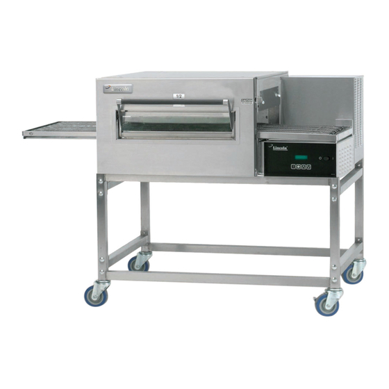
Page 30: General View
GENERAL VIEW → Old Model Number New Model Number → 1116-080-A (or A1) 1116-00z-U-Kxxxx → 1116-062-8R 1116-00z-U-Kxxxx → 1116-023-8 1116-00z-U-Kxxxx → 1117-080-A (or A1) 1117-00z-U-Kxxxx → 1117-023-8 1117-00z-U-Kxxxx → 1130-080-A (or A1) 1130-00z-U-Kxxxx → 1130-08H-A → 1131-080-A (or A1) 1131-00z-U-Kxxxx →... - Page 31 GENERAL VIEW Impinger II Express Service Manual - Domestic...
- Page 32 CONTROL BOX, FRONT → Old Model Number New Model Number → 1116-080-A (or A1) 1116-00z-U-Kxxxx → 1116-062-8R 1116-00z-U-Kxxxx → 1116-023-8 1116-00z-U-Kxxxx → 1117-080-A (or A1) 1117-00z-U-Kxxxx → 1117-023-8 1117-00z-U-Kxxxx LETTER PART NUMBER DESCRIPTION 369805 Switch, on/off 370408 Facia, pushbutton 370417 Control board 370409 Display only...
- Page 33 CONTROL BOX, FRONT VIEW → Old Model Number New Model Number → 1116-080-A (or A1) 1116-00z-U-Kxxxx → 1116-062-8R 1116-00z-U-Kxxxx → 1116-023-8 1116-00z-U-Kxxxx → 1117-080-A (or A1) 1117-00z-U-Kxxxx → 1117-023-8 1117-00z-U-Kxxxx Impinger II Express Service Manual - Domestic...
- Page 34 CONTROL BOX, FRONT Old Model Number New Model Number → 1130-080-A (or A1) 1130-00z-U-Kxxxx → 1130-08H-A → 1131-080-A (or A1) 1131-00z-U-Kxxxx → 1131-08H-A → 1132-080-A (or A1) 1132-00z-U-Kxxxx → 1132-08H-A 1172-00z-U-Kxxxx → 1132-002-8 1174-00z-U-Kxxxx → 1132-023-8 1132-00z-U-Kxxxx → 1133-080-A (or A1) 1133-00z-U-Kxxxx →...
- Page 35 CONTROL BOX, FRONT VIEW Old Model Number New Model Number → 1130-080-A (or A1) 1130-00z-U-Kxxxx → 1130-08H-A → 1131-080-A (or A1) 1131-00z-U-Kxxxx → 1131-08H-A → 1132-080-A (or A1) 1132-00z-U-Kxxxx → 1132-08H-A 1172-00z-U-Kxxxx → 1132-002-8 1174-00z-U-Kxxxx → 1132-023-8 1132-00z-U-Kxxxx → 1133-080-A (or A1) 1133-00z-U-Kxxxx →...
- Page 36 CONTROL BOX, REAR → Old Model Number New Model Number → 1116-080-A (or A1) 1116-00z-U-Kxxxx → 1116-062-8R 1116-00z-U-Kxxxx → 1116-023-8 1116-00z-U-Kxxxx → 1117-080-A (or A1) 1117-00z-U-Kxxxx → 1117-023-8 1117-00z-U-Kxxxx LETTER PART NUMBER DESCRIPTION 369192 Capacitor 370378 Conveyor motor assy. (S/N 2052462 & below) 370675 Conveyor motor assy.
- Page 37 CONTROL BOX, REAR VIEW → Old Model Number New Model Number → 1116-080-A (or A1) 1116-00z-U-Kxxxx → 1116-062-8R 1116-00z-U-Kxxxx → 1116-023-8 1116-00z-U-Kxxxx → 1117-080-A (or A1) 1117-00z-U-Kxxxx → 1117-023-8 1117-00z-U-Kxxxx Impinger II Express Service Manual - Domestic...
- Page 38 CONTROL BOX REAR Old Model Number New Model Number → 1130-080-A (or A1) 1130-00z-U-Kxxxx → 1130-08H-A → 1131-080-A (or A1) 1131-00z-U-Kxxxx → 1131-08H-A → 1132-080-A (or A1) 1132-00z-U-Kxxxx → 1132-08H-A 1172-00z-U-Kxxxx → 1132-002-8 1174-00z-U-Kxxxx → 1132-023-8 1132-00z-U-Kxxxx → 1133-080-A (or A1) 1133-00z-U-Kxxxx →...
- Page 39 CONTROL BOX, REAR VIEW Old Model Number New Model Number → 1130-080-A (or A1) 1130-00z-U-Kxxxx → 1130-08H-A → 1131-080-A (or A1) 1131-00z-U-Kxxxx → 1131-08H-A → 1132-080-A (or A1) 1132-00z-U-Kxxxx → 1132-08H-A 1172-00z-U-Kxxxx → 1132-002-8 1174-00z-U-Kxxxx → 1132-023-8 1132-00z-U-Kxxxx → 1133-080-A (or A1) 1133-00z-U-Kxxxx →...
- Page 40 OVEN BACK ASSEMBLY ALL MODELS LETTER PART NUMBER DESCRIPTION 369182 369899 Fan shroud 369655 Stand off Heating Elements 369183 208 Volt 369184 240 Volt 370648 208 Volt – Models 1130-08H-A & 1132-08H-A (S/N 10062053640 & below) 370645 240 Volt – Models 1131-08H-A & 1133-08H-A (S/N 10062053640 & below) 370690 208 Volt –...
- Page 41 OVEN BACK ASSEMBLY VIEW ALL MODELS Impinger II Express Service Manual - Domestic...
- Page 42 CONVEYOR / DOOR ALL MODELS LETTER PART NUMBER DESCRIPTION 369190 Coupler (S/N 2052462 & below) 370671 Coupler (S/N 2052463 & above) 369512 Coupling center (S/N 2052462 & below) 369269 Ball plunger (S/N 2052462 & below) 370116 Set screw (S/N 2052462 & below) Crumb pan, right (S/N 2045452 &...
- Page 43 CONVEYOR / DOOR VIEW ALL MODELS Impinger II Express Service Manual - Domestic...
- Page 44 ACCESS DOOR ALL MODELS (SN 0908210000875 AND BELOW) LETTER PART NUMBER DESCRIPTION 369110 Access Door Assembly 370724 Extrusion 369928 Dowel, Access Door 370726 Bracket Assembly 370725 Dowel Thread 370727 Bracket Assembly 370723 Glass Not Shown 369929 Retainer, Window Impinger II Express Service Manual - Domestic...
- Page 45 STAINLESS STEEL ACCESS DOOR ALL MODELS (SN 0908210000875 AND ABOVE) LETTER PART NUMBER DESCRIPTION 369110 Access Door Assembly 371140 Bracket Assembly, Left 371142 Dowel, Access Door 370722 Screw 371143 8-32 x 3/8 Hx Serr Flng 371141 Bracket Assembly, Right 370725 Dowel Thread 371144 Access Door Frame (top or bottom)
- Page 46 ADDENDUM A NEW STYLE OVEN STAND (BEGINNING MARCH 16, 2009) Insert the four Stand Side Bars (G) into the four holes located on each of the Front/Back Assemblies (A). Note: The Stand Side Bar that contains labels should be facing “out” so that the labels can be easily read by the operator. Attach the Stand Side Bars to the Front/Back Assemblies and tighten using the 1 ¾”...
- Page 47 This page intentionally left blank. Impinger II Express Service Manual - Domestic...
- Page 48 Impinger II Express Service Manual - Domestic...
Need help?
Do you have a question about the Impinger II Express Series and is the answer not in the manual?
Questions and answers