Table of Contents
Advertisement
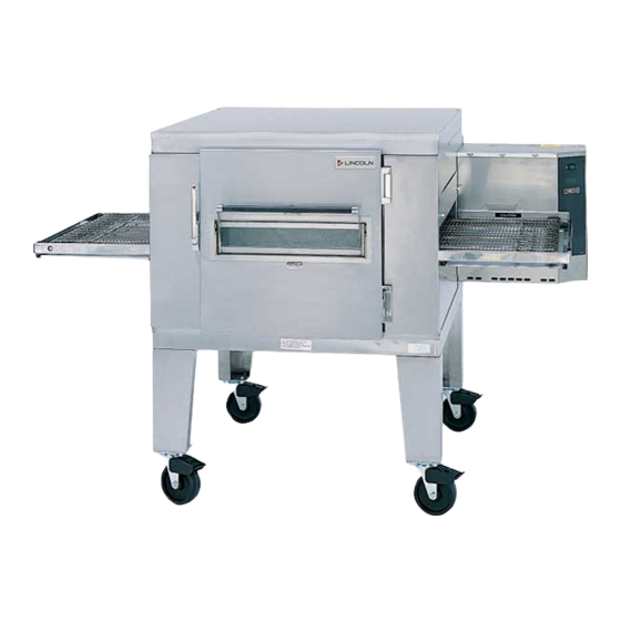
SERVICE MANUAL
(DOMESTIC)
IMPINGER CONVEYOR OVENS
MODEL SERIES 1000 - 1200 & 1400
Lincoln Foodservice Products, LLC
1111 North Hadley Road
Fort Wayne, Indiana 46804
United States of America
Phone : (800) 374-3004
U.S. Fax: (888) 790-8193 • Int'l Fax: (260) 436-0735
Technical Service Hot Line
(800) 678-9511
www.lincolnfp.com
1000SeriesSvc
REV: 1/5/07
Advertisement
Table of Contents
Troubleshooting

Subscribe to Our Youtube Channel
Related Manuals for Lincoln Impringer Conveyor Oven 1000


Summary of Contents for Lincoln Impringer Conveyor Oven 1000
- Page 1 SERVICE MANUAL (DOMESTIC) IMPINGER CONVEYOR OVENS MODEL SERIES 1000 - 1200 & 1400 Lincoln Foodservice Products, LLC 1111 North Hadley Road Fort Wayne, Indiana 46804 United States of America Phone : (800) 374-3004 U.S. Fax: (888) 790-8193 • Int’l Fax: (260) 436-0735...
-
Page 2: Table Of Contents
TABLE OF CONTENTS...2 SEQUENCE OF OPERATIONS 1000/1001/1004/1005/1200/1201/1204/1205 ...3 SEQUENCE OF OPERATIONS 1022 / 1023 / 1202 / 1203 ...4 SEQUENCE OF OPERATIONS 1040 / 1041 / 1240 / 1241 ...5 SCHEMATIC / 1000, 1001 ...8 SCHEMATIC / 1004, 1005 ...9 SCHEMATIC / 1022, 1023 –... -
Page 3: Sequence Of Operations 1000/1001/1004/1005/1200/1201/1204/1205
SEQUENCE OF OPERATIONS 1000/1001/1004/1005/1200/1201/1204/1205 MODEL 1000 - 120/230 VAC - 60HZ - NATURAL GAS MODEL 1001 - 120/230 VAC - 60HZ - L.P. GAS MODEL 1004 - 120/230 VAC - 60HZ - NATURAL GAS MODEL 1005 - 120/230 VAC - 60HZ - L.P. GAS MODEL 1200 - 120/230 VAC - 60HZ - NATURAL GAS/DUAL BELT MODEL 1201 - 120/230 VAC - 60HZ - L.P. -
Page 4: Sequence Of Operations 1022 / 1023 / 1202 / 1203
generator. The tach. generator is a DC voltage generator which supplies a voltage to the DC motor control board and is used as a reference for maintaining a constant conveyor speed. NOTE The 1200 Series Ovens utilize 2 complete conveyor drive systems. TIME TEMP DISPLAY The Time/Temp. -
Page 5: Sequence Of Operations 1040 / 1041 / 1240 / 1241
CONVEYOR DRIVE Closing the Fan Switch and the normally open Conveyor Switch supplies 120 VAC (S/N 100 to 4389) through a 3A Fuse, to the Motor Control Board. AC volts are converted to D.C. volts and are supplied to the Conveyor Motor at board terminals A1 and A2 through a D.P.D.T. - Page 6 TRANSFORMER (12.6 Upon closure of the Fan Switch, 120 VAC is supplied to the primary of the 12.6 VAC VAC) Transformer. The Transformer steps the voltage down to 12.6 VAC (normally 13 to 14 VAC) with a center tap, and supplies power to the Time/ Temp. Display. The voltage from each leg of the Transformer' s secondary to the center tap should be one half of the secondary voltage.
- Page 7 TIME TEMP DISPLAY Closing the Oven Fan Switch supplies 120 VAC, through the Power Transformer, to the primary of the Time/Temp. Transformer. The secondary output of the Transformers, 12.5to 15 VAC with a center tap, is supplies to terminals 1, 2, and3 of the Time/Temp.
-
Page 8: Schematic / 1000, 1001
SCHEMATIC / 1000, 1001 Impinger I -–1000 Series Service Manual - Domestic... -
Page 9: Schematic / 1004, 1005
SCHEMATIC / 1004, 1005 Impinger I -–1000 Series Service Manual - Domestic... -
Page 10: Schematic / 1022, 1023 - S/N Q19077 & Below
SCHEMATIC / 1022, 1023 – S/N Q19077 & BELOW Impinger I -–1000 Series Service Manual - Domestic... -
Page 11: Schematic / 1022, 1023 - S/N Q19078 & Above
SCHEMATIC / 1022, 1023 – S/N Q19078 & ABOVE Impinger I -–1000 Series Service Manual - Domestic... -
Page 12: Schematic / 1040, 1041 - S/N Q14279 & Below
SCHEMATIC / 1040, 1041 – S/N Q14279 & BELOW Impinger I -–1000 Series Service Manual - Domestic... -
Page 13: Schematic / 1040, 1041 - S/N Q14280 & Above
SCHEMATIC / 1040, 1041 – S/N Q14280 & ABOVE Impinger I -–1000 Series Service Manual - Domestic... -
Page 14: Schematic / 1200, 1201
SCHEMATIC / 1200, 1201 Impinger I -–1000 Series Service Manual - Domestic... -
Page 15: Schematic / 1202, 1203 S/N Q14790 & Below
SCHEMATIC / 1202, 1203 S/N Q14790 & BELOW Impinger I -–1000 Series Service Manual - Domestic... -
Page 16: Schematic / 1202, 1203 S/N Q14791 & Above
SCHEMATIC / 1202, 1203 S/N Q14791 & ABOVE Impinger I -–1000 Series Service Manual - Domestic... -
Page 17: Schematic / 1204, 1205
SCHEMATIC / 1204, 1205 Impinger I -–1000 Series Service Manual - Domestic... -
Page 18: Schematic / 1240, 1241 - S/N Q14279 & Below
SCHEMATIC / 1240, 1241 – S/N Q14279 & BELOW Impinger I -–1000 Series Service Manual - Domestic... -
Page 19: Schematic / 1240, 1241 - S/N Q14280 & Above
SCHEMATIC / 1240, 1241 – S/N Q14280 & ABOVE Impinger I -–1000 Series Service Manual - Domestic... -
Page 20: Troubleshooting Guide 1000 & 1200
TROUBLESHOOTING GUIDE 1000 & 1200 SYMPTOM POSSIBLE CAUSE Oven fan will not run Incoming Power Supply NOTE: (Export Ovens) Oven Fan Fuse(s) Fuse Holder Fan Switch Main Relay Fan Motor Capacitor No Main Fan Cool Cool Down Thermostat Down No Control Box Main Fan Relay Cooling(For ovens equipped with Control... - Page 21 Air Pressure Switch Transformer, 24 VAC NOTE: (Model 1004 & 1005) Burner Motor Relay Burner Blower Motor Centrifugal Switch of Burner Blower Motor For ovens with Ignition Control and Valve Johnson Controls Assembly Ignition Control (For ovens with Honeywell Ignition control, See Pg.
- Page 22 Pilot flame but no main Flame Sensor flame Ignition Control and Valve Assembly For ovens with Centrifugal Switch of Burner Honeywell ignition Blower Motor control NOTE: Ignition Control No Pilot Pilot Shut-off Valve Pilot Tube Pilot Orifice Burner Ignitor (There should be a visible pilot flame at this time.) To check for proper flame sensor operation, connect a digital multimeter (capable of measuring D.
- Page 23 Spark Ignitor (Flame Sensor) Pilot flame but no main flame Red Indicator Light is Temperature Control Valve on, but no main (Robert Shaw) flame(For ovens with Main Orifice mechanical thermostat) (For ovens with Temperature Control Electronic Potentiometer Temperature Control) NOTE: Ovens S/N Q18037 and above, the potentiometer is internal to temperature control. Proceed to next component.
- Page 24 1 on 2 on 3 on 4 off 5 off 6 off 1 on 2 on 3 on 4 on 5 off 6 off 1 on 2 on 3 on 4 on 5 on 6 off - Pilot Shield missing or warped, Flame Sensor bad, Pilot 1 on 2 on 3 on 4 on 5 on 6 on - However, Main Orifice would not be intermittent problem.
-
Page 25: Troubleshooting Guide
ELECTRIC OVENS MODEL SERIES 1000 & 1200 SYMPTOM POSSIBLE CAUSE Oven fan will not run Incoming Power Supply NOTE: (Export Ovens) Oven Fan Fuse(s) Fuse Holder Fan Switch Main Relay Fan Motor Capacitor No Main Fan Cool Cool Down Thermostat Down No control box cooling Main Fan Relay... - Page 26 Temperature Control Board Temperature Control Potentiometer Thermocouple Probe Mercury Contactor(s) 50 Amp Fuses Heater Elements Oven heats with switch Mercury Contactor(s) Conveyor will not run Voltage Supply (S/N 100-4389) 3 Amp Fuse Fuse Holder Conveyor Switch D. C. Motor Control Board Check for 120 VAC input to temperature control board.
- Page 27 Speed Control Potentiometer Reversing Switch Conveyor Drive Motor Conveyor will not Voltage Supply run(S/N 4390 to Q190771000 Series) (S/N 4390- Q147901200 Series) Fuseholder Fan Switch Conveyor Switch NOTE: (Dual Belt Ovens) Speed Adjustment Potentiometer DC Motor Control Board Impinger I -–1000 Series Service Manual - Domestic This is a 0 to 400 ohm or 0 to 500 ohm, 10-turn potentiometer.
- Page 28 Conveyor Gear Motor Conveyor Conveyor speed Power Supply varying or intermittent Tach generator and DC Motor Control Board DC Gearmotor Conveyor will not Voltage Supply run(S/N Q19078 & Up1000 Series) (S/N Fan Switch Q14791 & Up1200 Conveyor Switch Series) Conveyor Fuse (3A) Fuseholder If DC voltage is present at A+ and A- and the motor does not run, first check the mini breaker and then...
- Page 29 Conveyor Control(Stepper) Transformer Speed Adjustment Potentiometer Conveyor Motor(Stepper) Control Conveyor Drive (Stepper) Motor Time/Temp Display 12.6 VAC Power Supply NOTE: (Dual Belt Ovens) Impinger I -–1000 Series Service Manual - Domestic Check for 120 VAC supply to primary of transformer, if voltage is not present, trace wiring back to the fuse-holder.
- Page 30 Temp Display out or NOTE: Time/Temp displays inaccurate use two types of temperature sensor, Thermistor Probe – 2 yellow wires Thermocouple Probe 1 red wire and 1 white wire Thermistor Probe Thermocouple Probe Erratic time/temp display Temp Display inaccurate erratic, or inoperative Time display inaccurate erratic, or inoperative Optical Encoder...
- Page 31 Time Display inaccurate, erratic, or inoperative(S/N Conveyor Drive (Stepper) Q19078 & Above1000 Control Series) (S/N Q14791 & Above1200 Series) Magnet Hall Effect Sensor Conveyor Drive (Stepper) Control Impinger I -–1000 Series Service Manual - Domestic Perform all checks as in the above evaluation. If the time check is okay, refer to the next section.
-
Page 32: Removal, Installation & Adjustments
REMOVAL, INSTALLATION & ADJUSTMENTS BEFORE REMOVING OR INSTALLING ANY COMPONENT IN THE IMPINGER OVEN BE SURE TO DISCONNECT ELECTRICAL POWER AND GAS SUPPLY MOTOR, MAIN FAN Shut off power at main breaker. Remove flue by taking out the two (2) mounting screws. Remove louvered motor cover from back of oven. - Page 33 9 3/4 IN. 1/8 IN. Reinstall and locate fan so that the front of fan blades are 9 3/4" from inside of oven back. (See Drawing) S. N. 4613 & Above (GAS) S. N. 4768 & Above (ELECTRIC) FAN SPIDER FAN HUB CONE Reinstall and locate fan so that the bottom of the fan spider is 1 1/2"...
-
Page 34: Thermostat, Cooling Fan
THERMOSTAT, COOLING FAN Shut off power at main breaker. Remove control panel top and front cover. Remove lead wires and mark for reassembly. Remove two (2) screws and remove thermostat. Reassemble in reverse order. BURNER BLOWER MOTOR Shut off power at main breaker. Remove control panel top and front panel. -
Page 35: Air Pressure Switch
CENTRIFUGAL MOTOR SWITCH WHITE BLACK (BUTTSPLICE CONNECTORS PROVIDED FOR 120 VAC POWER SUPPLY) BLOWER WHEEL, BURNER This is part of the burner blower motor assembly. TO REMOVE THE BLOWER WHEEL FOR PERIODIC CLEANING: Shut off power at main breaker. Remove control panel top and front cover. Remove air shutter held by 3 screws. -
Page 36: Burner Assembly
BURNER ASSEMBLY Shut off power at main breaker. Shut off gas supply. Remove control panel top and front panel. Remove gas control valve (See "GAS CONTROL VALVE") Disconnect pilot tube. Remove thermostat or solenoid valve. Remove four (4) phillips screws that secure the burner backing plate. Remove burner assembly from housing, the main and pilot orifice, flame target, pilot shield (main and extension), flame sensor, and burner ignitor can now be changed or serviced as needed. -
Page 37: Manifold Pressure - Adjustment
MANIFOLD PRESSURE - ADJUSTMENT Remove control panel top and front cover. WITH ELECTRIC POWER AND GAS OFF: remove the outlet pressure tap plug from the gas control valve and install the adapter fitting and manometer. Turn on electric power and gas and start-up oven. With oven at full fire, manifold pressure should be (3.5"W.C. -
Page 38: Thermocouple- Replacement
TEMPERATURE CONTROL POTENTIOMETER – REPLACEMENT Remove control panel top and front cover. Remove one screw from control knob guard and move guard to one side. Remove knob and locknut on control pot. shaft and push out. Remove three (3) wires from temperature control board. Note wire numbers and location. Reassemble in reverse order. -
Page 39: Heating Element
HEATING ELEMENT Shut off power at main breaker. Remove rear motor cover. Disconnect heater element wire and mark for reassembly. Remove oven back assembly. NOTE: For ovens SN 4768 and above, remove fan shroud. Remove two (2) mounting screws and remove heating element. Reassemble in reverse order. - Page 40 24V (GND) TO PILOT LIGHT 24V FROM TRANSFORMER INSULATED MALE TAB CONNECTOR BLUE FROM VALVE BLACK FROM VALVE #3 RED FROM VALVE TO PILOT LIGHT Impinger I -–1000 Series Service Manual - Domestic WHITE FROM PILOT LIGHT BUTT SPLICE AND NEW GREEN WIRE SUPPLIED IN KIT WHITE FROM PILOT LIGHT...
-
Page 41: Flame Sensor
FLAME SENSOR Shut off power at main breaker. Remove control panel top and front cover. Remove burner assembly (see burner assembly). Disconnect one (1) wire from flame sensor. Remove flame sensor by removing one (1) mounting nut. Reassemble in reverse order. NOTE: Be sure flame sensor is not bent or touching any other burner parts. - Page 42 PILOT ORIFICE - BURNER Shut off power at main breaker. Shut off gas supply. Remove burner assembly (see Burner Assembly). Remove pilot line from pilot orifice. Remove pilot orifice from burner igniter. Reassemble in reverse order. MAIN ORIFICE - BURNER Shut off power at main breaker.
- Page 43 CONVEYOR MOTOR REPLACEMENT - BALDOR 1000 SERIES SN 4390 - 14974 1200 SERIES SN 4390 – 14791 Shut off power at main breaker. Remove control panel top and front cover. Remove the conveyor drive chain from the motor sprocket. Remove chain guard. Remove the sprocket from the conveyor motor shaft by loosening the set screws and sliding the sprocket off the shaft.
- Page 44 OPTICAL ENCODER ASSEMBLY Shut off power at main breaker. Remove conveyor motor assembly .If replacing with new assembly, cut wires to remove as new wires and plug are provided. If only removing for access to coupling follow step 4. Remove pins from connectors with pin extractor tool, P/N 369600. Loosen dust cover screws and pull dust cover away from motor.
- Page 45 PLACE DIGITAL VOLTMETER LEADS ON terminal S1 and S2, adjust the max pot. for a reading of 3.4 VDC. Place METER LEADS on terminals A1 and A2. Adjust the reg. pot. for a reading of 125 VDC. NOTE: In some instances when the input AC voltage runs on the high side of the normal input range, you may have difficulty adjusting the max.
- Page 46 D. C. MOTOR CONTROL BOARD SN 4390 - 14974 1000 SERIES GAS OVENS SN 4390 - 14790 1200 SERIES Three different styles of control boards have been used and all three are still usable. All three were supplied under the same part number. STYLE 1 CONTROL BOARD ADJUSTMENT NOTE: A digital meter must be used for this adjustment.
- Page 47 checked until both "MIN" and "MAX" are in proper adjustment. Measure the speed of the conveyor and adjust the time/temp. display if necessary. Seal pots with Glyptol or nail polish. NOTE: Occasionally a new board (Style 2 and 3 only) is so far out of adjustment that you will be unable to adjust the correct voltage.
-
Page 48: Dip Switches
STEPPER CONTROL - ADJUSTMENT S/N 14975 AND ABOVE 1000 SERIES GAS OVEN S/N 14792 AND ABOVE 1200 SERIES GAS OVEN Min. Max. Conveyor Conveyor Speed Adj. Speed Adj. POTENTIOMETER With power off, the five (5) dip switches located on the conveyor control (see drawing above) should be set as below. -
Page 49: Drive End
REVERSING CONVEYOR DIRECTION SN 100-4389 (BODINE) Shut off power at main breaker. Remove control panel top. Turn reversing switch (located on relay box) to obtain desired belt direction. Reassemble in reverse order. SN 4390-14974 1000 SERIES GAS OVEN SN 4390-14791 1200 SERIES All ovens leaving our plant are wired to operate conveyors from left to right. - Page 50 BEARING, CONVEYOR SN 2164 AND ABOVE Remove conveyor from oven and place on a flat work surface. Remove connecting links from conveyor belting. See Installation and Operating Instructions Manual . Remove conveyor belting from conveyor DRIVE END Remove drive sprocket from drive shaft. Remove two (2) allen head bolts.
-
Page 51: Temperature Gauge - Replacement
TEMPERATURE GAUGE - REPLACEMENT Shut off power at main breaker. Remove control panel top. Disconnect thermocouple from temperature gauge. Remove two (2) mounting bolts and remove temperature gauge. Reassemble in reverse order. THERMISTOR - REPLACEMENT Shut off power at main breaker. Remove control panel top. -
Page 52: Switch Settings
ALL 1000 & 1200 SERIES OVENS SWITCH SETTINGS TYPE I TYPE II TYPE III (Baldor Motor) TYPE III (Stepper Motor) TYPE IV (Baldor Motor) TYPE IV (Stepper Motor) *These switches are for Hertz settings (OFF=60HZ) & (ON=50HZ) **These switches are for temperature read-out (OFF=Degrees F) & (ON=Degrees C) Turn power on. - Page 53 Type IV has adjustment pots. In the center board. If temperature is still inaccurate after above calibration and troubleshooting, use the following to check the High Temp. Pot. normally the High Temp. Pot. does not require adjustment. Occasionally the pot is accidentally moved or needs adjustment. Refer to the following drawing showing proper adjustment of the High Temp.
- Page 54 Dip Switch TYPE I TYPE II TYPE III NOTE: When on 50 HZ power, dip switch #2 must be "ON" With power ON turn time and temperature cal. pot. fully counterclockwise. Display should read: (Wait 15-20 seconds) TYPE I 9:30 + 10 sec.475 + 10° F TYPE II 9:20 + 10 sec.
- Page 55 THE FOLLOWING ITEMS ARE USED IN THE MODEL 1030, 1046, 1047 IMPINGER OVEN (EXPORT) AIR PRESSURE SWITCHES - REPLACEMENT AND ADJUSTMENT Remove control panel top. Disconnect wires from switch making note of wire number and location for reinstallation. Remove air tube from switch assembly. Remove switch from wire hanger.
-
Page 56: Spark Generator - Replacement
IGNITION CONTROL - REPLACEMENT Remove control panel top and front cover. Loosen two (2) locking screws on front cover of relay (approx. 1/2 turn). Remove front portion of relay by pulling straight out (rocking motion). Remove wires from plug-in terminal strip, note wire numbers and locations. Remove two (2) screws from mounting bracket and remove. - Page 57 BURNER ALARM LIGHT - REPLACEMENT Remove control panel top and front cover. Remove two (2) wires from light assembly, note wire number and location. Grasp body of light assembly and slide sideways to remove. Reassemble in reverse order and check. PILOT LIGHT (220V) - REPLACEMENT Remove control panel top and front cover.
- Page 58 TEMPERATURE CONTROL POTENTIOMETER - REPLACEMENT Remove control panel top and front cover. Remove one screw from control knob guard and move guard to one side. Remove knob and locknut on control pot shaft and pushout. Remove three (3) wires from temperature control board, note wire colors and location. Install new control pot.
- Page 59 THIS PAGE INTENTIONALLY LEFT BLANK. Impinger I -–1000 Series Service Manual - Domestic...
-
Page 60: Parts / Model Series 1000 & 1200 - General
PARTS / MODEL SERIES 1000 & 1200 - GENERAL LETTER PART NO. 369003 369207 369337 369110 369209 369828 369157 1534 369057 369643 1009 369062 369046 369367 369140 369903 369141 369139 369058 369211 369369 369203 369749 369204 369373 369205 369651 369379 369052 369030 369328... -
Page 61: Blow Up / 1000, 1200 - General
BLOW UP / 1000, 1200 – GENERAL Impinger I -–1000 Series Service Manual - Domestic... -
Page 62: Parts / Access Door & 1050 Door
PARTS / ACCESS DOOR & 1050 DOOR LETTER PART NO. 369110 369310 369377 369308 369111 369334 350638 369311 369309 369336 369906 369230 369112 350257 369229 369337 369207 369004 369031 369015 369049 369051 369050 369003 369926 369925 369927 369930 369931 369929 DESCRIPTION Complete Access Window Assy. -
Page 63: Blow Up / Access Door & 1050 Door
BLOW UP / ACCESS DOOR & 1050 DOOR Impinger I -–1000 Series Service Manual - Domestic... -
Page 64: Parts / Model 1000,1001,1050,1051,1004, &1005 - S/N 100 To 4389
PARTS / MODEL 1000,1001,1050,1051,1004, &1005 – S/N 100 TO 4389 LETTER PART NO. 369012 369013 369014 369066 369260 350225 369104 369025 369022 369113 369114 369115 369032 369008 369079 369080 369007 369902 N. L. A 369531 369366 369009 369029 369108 369263 369393 369344 369006... -
Page 65: Blow Up / 1000, 1001, 1050, 1051, 1004, & 1005 S/N 100 To 4389
BLOW UP / 1000, 1001, 1050, 1051, 1004, & 1005 S/N 100 TO 4389 Impinger I -–1000 Series Service Manual - Domestic... -
Page 66: Parts / Model 1000,1001,1004, And 1005 S/N 4390 & Above
PARTS / MODEL 1000,1001,1004, AND 1005 S/N 4390 & ABOVE LETTER 369247 369248 369064 369012 369013 369014 369158 350705 369260 350225 369104 369507 369025 369032 369155 357028 369201 369240 369173 369363 369154 369007 369902 N. L. A. 369531 369366 369331 369167 369172 369029... -
Page 67: Blow Up 1000, 1001, 1004, 1005 S/N 4390 & Above
BLOW UP 1000, 1001, 1004, 1005 S/N 4390 & ABOVE Impinger I -–1000 Series Service Manual - Domestic... -
Page 68: Parts / 1022-1023
LETTER 369247 369012 369129 369013 369130 369064 369248 369260 369066 369158 369605 350225 369128 369022 369113 369114 369115 369120 369127 357067 353014 369118 369007 369902 369154 369640 357028 369201 369240 369167 370046 369172 369029 369342 369193 369340 369132 369173 369131 369032 369124 369535... -
Page 69: Blow Up / 1022, 1023
BLOW UP / 1022, 1023 Impinger I -–1000 Series Service Manual - Domestic... -
Page 70: Parts / 1040-1041
LETTER 369247 369012 369013 369014 369248 369158 369066 369260 369605 350225 369104 369507 369025 369032 369155 369640 357028 369201 369240 3691730 369363 369131 369270 N. L. A. 369531 369366 369331 369193 369167 370046 369172 369316 369263 369393 369344 369317 369398 369072 369099 369144... -
Page 71: Blow Up / 1040, 1041
BLOW UP / 1040, 1041 Impinger I -–1000 Series Service Manual - Domestic... -
Page 72: Parts / 1200, 1201, 1204 And 1205
PARTS / 1200, 1201, 1204 AND 1205 LETTER 369012 369014 369252 369248 369247 369260 350225 369507 369104 369193 369025 369032 369007 369902 369173 369363 N. L. A 369531 369366 369331 369167 370046 369172 369108 369263 369393 369344 369006 369086 369072 369099 369144 369202... -
Page 73: Blow Up / 1200, 1201, 1204, 1205
BLOW UP / 1200, 1201, 1204, 1205 Impinger I -–1000 Series Service Manual - Domestic... -
Page 74: Parts / 1202-1203
LETTER 369247 369129 369012 369013 369130 369248 369252 369260 350225 369128 369025 369120 369127 353014 369118 369007 369902 369119 369134 369193 369167 370046 369172 369342 369340 369132 369173 369032 369131 369124 369067 369253 369254 PARTS / 1202-1203 DESCRIPTION Shaft Lock Ring Fuseholder, 15A Fuseholder Fuse, 3 Amp... -
Page 75: Blow Up / 1202, 1203
BLOW UP / 1202, 1203 Impinger I -–1000 Series Service Manual - Domestic... -
Page 76: Parts / 1240-1241
LETTER 369012 369014 369248 369247 369260 350225 369507 369104 369025 369032 369363 369131 369270 N. L. A. 369531 369366 369331 369193 369167 370046 369172 369316 369263 369393 369344 369317 369398 369086 369072 369099 369144 369202 369075 369073 369100 369076 369142 369007 369902 369252... -
Page 77: Blow Up / 1240, 1241
BLOW UP / 1240, 1241 Impinger I -–1000 Series Service Manual - Domestic... -
Page 78: Parts / Oven Back - Gas
LETTER 369048 369212 369214 369192 369045 369306 369646 369647 369213 N.L.A. 369026 369215 369028 369020 369027 369545 369547 Not Shown 369318 Not Shown 369321 PARTS / OVEN BACK - GAS DESCRIPTION Motor and Fan Cover Motor, S/N begins with a"Q" Motor, 50 Hz, 240V Capacitor 7.5 MFD, 370 VAC Oven Back- S/N 4612 &... -
Page 79: Blow Up / Oven Back - Gas
BLOW UP / OVEN BACK – GAS Impinger I -–1000 Series Service Manual - Domestic... -
Page 80: Parts / Oven Back- Electric
LETTER 369699 369212 369214 369192 369307 369122 369287 369315 369647 369213 N.L.A 369646 369026 369215 369028 369020 369027 369547 Not Shown 369319 Not Shown 369320 Not Shown 369322 Not Shown 369323 PARTS / OVEN BACK- ELECTRIC DESCRIPTION Rear Cover Assy. Motor, S/N begins with a "Q"... -
Page 81: Blow Up / Oven Back - Electric
BLOW UP / OVEN BACK – ELECTRIC Impinger I -–1000 Series Service Manual - Domestic... -
Page 82: Parts / Conveyor Motor Assembly S/N 4390 & Above
PARTS / CONVEYOR MOTOR ASSEMBLY S/N 4390 & ABOVE LETTER 369291 369384 369294 369296 369290 369151 369146 369294 369292 369297 369156 369293 369150 369298 369299 350247 369295 369603 369737 369900 369658 369736 DESCRIPTION Motor, DC - Conveyor Motor Brush Assy. #4 Lockwasher Screw, 4-40 x 1/4 Optical Encoder Assy. -
Page 83: Blow Up / Conveyor Motor Assembly S/N 4390 & Above
BLOW UP / CONVEYOR MOTOR ASSEMBLY S/N 4390 & ABOVE Impinger I -–1000 Series Service Manual - Domestic... -
Page 84: Parts / Series 1000 - Conveyor
PARTS / SERIES 1000 – CONVEYOR LETTER 369002 369314 369835 369312 369160 369641 369220 369005 369237 369161 369066 369413 369219 369644 369206 369163 369362 369143 369036 N.L.A. 369380 369060 369037 369034 369035 369042 369039 369038 369043 369059 369040 DESCRIPTION Tension Knob, Conveyor Roll, Conveyor-Notched Conveyor Frame Assy. -
Page 85: Blow Up / Series 1000 Conveyor
BLOW UP / SERIES 1000 CONVEYOR Impinger I -–1000 Series Service Manual - Domestic... -
Page 86: Parts / Series 1200 - Conveyor Control
PARTS / SERIES 1200 - CONVEYOR CONTROL LETTER 369012 369013 369240 369155 369640 357028 369201 369272 357028 369201 369154 N. L.A. 369665 369289 369242 369696 369124 369605 DESCRIPTION SEE PAGE 82 Fuseholder Fuse, 3 Amp Hi Hat Conveyor Motor Control, "A" S/N Q4613 to Q14973 Conveyor Control (Stepper) S/N Q14974 &... -
Page 87: Blow Up / Series 1200 - Conveyor Control
BLOW UP / SERIES 1200 – CONVEYOR CONTROL Impinger I -–1000 Series Service Manual - Domestic... -
Page 88: Parts / Series 1200 - Conveyor
PARTS / SERIES 1200 – CONVEYOR LETTER 369277 369275 369276 369274 369279 369278 369241 369242 369005 369280 369284 369039 369038 369281 369160 350238 369697 369282 369206 369273 Not Shown 369249 Not Shown 369250 Not Shown 369817 Not Shown 369818 DESCRIPTION Retaining Block, Inner Flanged Bearing, .50 ID Inner Drive Shaft... -
Page 89: Blow Up / Series 1200 - Conveyor
BLOW UP / SERIES 1200 – CONVEYOR Impinger I -–1000 Series Service Manual - Domestic... - Page 90 This page intentionally left blank. Impinger I -–1000 Series Service Manual - Domestic...
- Page 91 This page intentionally left blank. Impinger I -–1000 Series Service Manual - Domestic...
- Page 92 Impinger I -–1000 Series Service Manual - Domestic...
Need help?
Do you have a question about the Impringer Conveyor Oven 1000 and is the answer not in the manual?
Questions and answers
Amperage draw on model 1000 gas pizza oven
this oven need be installed under **** hood