Advertisement
Quick Links
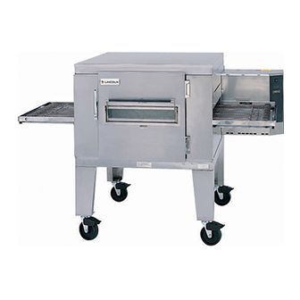
SERVICE MANUAL
(INTERNATIONAL)
IMPINGER CONVEYOR OVENS
MODEL 1433-000-E, 1434-000-E,
1456, 1457
WITH PUSH BUTTON CONTROLS
Lincoln Foodservice Products, LLC
1111 North Hadley Road
Fort Wayne, Indiana 46804
United States of America
Phone : (800) 374-3004
U.S. Fax: (888) 790-8193 • Int'l Fax: (260) 436-0735
Technical Service Hot Line
(800) 678-9511
www.lincolnfp.com
1450digexport
REV 1/5/07
Advertisement

Subscribe to Our Youtube Channel
Related Manuals for Lincoln 1433-000-E


Summary of Contents for Lincoln 1433-000-E
- Page 1 SERVICE MANUAL (INTERNATIONAL) IMPINGER CONVEYOR OVENS MODEL 1433-000-E, 1434-000-E, 1456, 1457 WITH PUSH BUTTON CONTROLS Lincoln Foodservice Products, LLC 1111 North Hadley Road Fort Wayne, Indiana 46804 United States of America Phone : (800) 374-3004 U.S. Fax: (888) 790-8193 • Int’l Fax: (260) 436-0735...
-
Page 2: Sequence Of Operation
SEQUENCE OF OPERATION IMPINGER ADVANTAGE SERIAL NUMBER N28654 AND ABOVE (OVENS WITH PUSH BUTTON CONTROLS) MODEL 1433-000-E 230VAC 50 HZ. NAT. GAS MODEL 1434-000-E 230VAC 50 HZ. LP GAS MODEL 1456 220/240VAC 50 HZ. NAT. GAS MODEL 1457 220/240VAC 50 HZ. -
Page 3: Schematic Diagram
SCHEMATIC DIAGRAM MODEL 1433-000-E, 1434-000-E SERIAL NUMBER N28654 TO N31348 Impinger I – Adv Digital – Gas Service Manual – International... - Page 4 SCHEMATIC DIAGRAM MODEL 1456, 1457 SERIAL NUMBER N28654 TO N31348 Impinger I – Adv Digital – Gas Service Manual – International...
- Page 5 SCHEMATIC DIAGRAM MODEL 1433-000-E, 1434-000-E, 1456, 1457 SERIAL NUMBER N31349 AND ABOVE Impinger I – Adv Digital – Gas Service Manual – International...
-
Page 6: Troubleshooting Guide
TROUBLESHOOTING GUIDE IMPINGER ADVANTAGE GAS OVENS SERIAL NUMBER N28654 AND ABOVE (OVENS WITH PUSH BUTTON CONTROLS) SYMPTOM POSSIBLE CAUSE EVALUATION Oven fan will not run Incoming power supply Check circuit breaker, reset if required. Check power plug to be sure it is firmly in receptacle. Measure incoming power, call power co. - Page 7 WITH POWER OFF: Remove 3 prong plug (on gas valve) and measure continuity between terminals 2 and 3. If no continuity, check the following: Proper gas pressure supply to gas valve as marked on the oven specification plate. Check for proper adjustment of the gas pressure switch, 10 for Nat.
- Page 8 not stay on, check the reset button for the ignition control. If the above check okay, replace ignition control. Oven will not heat Main fan If not operating, refer to “Oven fan will not run” S/N N31349 and Above Gas supply Check for adequate gas supply and be sure that the manual gas shut off valve is open.
- Page 9 there is voltage to the pilot valve, but there is no gas pressure, replace gas valve. Pilot tube Check for gas pressure at pilot tube. Disconnect pilot tube at burner and connect manometer. If there is no gas pressure, check for blockage in pilot tube. Repair or replace as needed.
- Page 10 Oven control If the thermocouple checks good, but the oven control display indicates that there is a thermocouple failure, replace the oven control. If the oven control indicates a temperature reading, but the oven will not heat, proceed. Thermocouple WITH POWER ON AND THERMOCOUPLE ATTACHED TO THE OVEN CONTROL: Measure the DC millivolt output of the thermocouple.
- Page 11 sensor (sensor is located in the conveyor motor). Measure voltage at the motor connector, red wire and yellow wire. Voltage should be approx. 10VDC. If no voltage is present, trace wiring back to oven control. If there is no voltage output at the oven control, replace oven control.
-
Page 12: Removal, Installation & Adjustments
REMOVAL, INSTALLATION & ADJUSTMENTS IMPINGER ADVANTAGE SERIES CAUTION! BEFORE REMOVING OR INSTALLING ANY COMPONENT IN THE IMPINGER OVEN BE SURE TO DISCONNECT ELECTRICAL POWER AND GAS SUPPLY MOTOR, MAIN FAN - REPLACEMENT 1. Shut off power at main breaker. 2. Remove louvered motor cover from back of oven. 3. - Page 13 THERMOSTAT, COOLING FAN - REPLACEMENT 1. Shut off power at main breaker. 2. Remove control panel top and front cover. 3. Remove lead wires and mark for reassembly. 4. Remove two (2) screws and remove thermostat. 5. Reassemble in reverse order. BURNER BLOWER MOTOR - REPLACEMENT 1.
- Page 14 8. Remove burner assembly from housing, the main and pilot orifice, flame target, pilot shield (main and extension), burner ignitor can now be changed or serviced as needed. 9. Reassemble in reverse order. Check all gas line fittings for leaks. GAS CONTROL VALVE –...
- Page 15 THERMOSTAT, OVEN CAVITY HI-LIMIT – REPLACEMENT 1. Shut off power at main breaker. 2. Remove control box cover and front panel. Remove conveyor assembly and fingers from oven to aid in removal of thermostat from oven. 3. Disconnect wires from thermostat and mark for reassembly. 4.
- Page 16 THERMOCOUPLE MEASURMENT TEMPERATURE D.C. MILLVOLTS (APPROX.) 200° 250° 300° 350° 400° 450° 500° 550° 10.4 600° 11.5 CONTROL TRANSFORMER - REPLACEMENT 1. Shut power off at main breaker. 2. Remove control panel top and front cover. 3. Remove two (2) wires on primary side, note color and location. 4.
- Page 17 6. Remove assembly and replace main orifice. 7. Reassemble in reverse order and check system operation. NOTE: Check all gas line fittings for leaks. PILOT ORIFICE - REPLACEMENT 1. Shut off power at main breaker. 2. Shut off gas supply. 3.
- Page 18 GENERAL VIEW ADVANTAGE SERIES LETTER PART NUMBER DESCRIPTION 369003 Door hinge 369110 Access window assembly 369337 Retainer (old style) 369929 Retainer (new style) 369828 Handle spacer 369209 Latch & strike 369310 Screw, 6-32 x 3/16” 369308 Bottom, access window 369334 Access door glass 369309 Top, access window...
- Page 19 Impinger I – Adv Digital – Gas Service Manual – International...
- Page 20 CONTROL BOX 1456,1457,1433-000-E, 1434-000-E LETTER PART # DESCRIPTION 369062 Top, Control Panel 370355 Oven Control 370363 Front Cover Assembly 370354 Facia, Label 369432 Switch, On/Off 369580 Gas Valve, Multi Block (S/N N31348 & Below) 370433 Gas Valve (S/N N31349 & Above)
- Page 21 Impinger I – Adv Digital – Gas Service Manual – International...
- Page 22 OVEN BACK ADVANTAGE SERIES GAS AND ELECTRIC LETTER PART NUMBER DESCRIPTION 369808 Cover, motor (gas ovens) 370140 Cover, motor (electric ovens) 369214 Motor, main fan (50 Hz.) 369033 Motor clamp 369215 Motor support assembly 369192 Capacitor, 7.5 MFD 369306 Oven back assembly, gas oven 369646 Stand-off 369647...
- Page 23 Impinger I – Adv Digital – Gas Service Manual – International...
-
Page 24: Conveyor 1450 Series
CONVEYOR 1450 SERIES LETTER PART NUMBER DESCRIPTION 369830 Complete conveyor assembly 369816 Conveyor belt, complete (30 inch wide belt) 369163 Conveyor belt, complete (32 inch wide belt) 370092 Conveyor belt, 1 foot section (30 inch wide belt) 369362 Conveyor belt, 1 foot section (32 inch wide belt) 369825 Retaining ring 369813... - Page 25 Impinger I – Adv Digital – Gas Service Manual – International...
- Page 26 This page intentionally left blank. Impinger I – Adv Digital – Gas Service Manual – International...
- Page 27 This page intentionally left blank. Impinger I – Adv Digital – Gas Service Manual – International...
- Page 28 Impinger I – Adv Digital – Gas Service Manual – International...
Need help?
Do you have a question about the 1433-000-E and is the answer not in the manual?
Questions and answers