Table of Contents
Advertisement
Quick Links
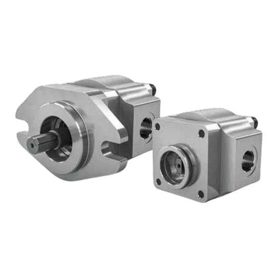
Internal gear pumps Eckerle EIPS
1.
Internal gear pumps Eckerle EIPC EIPH
2.
Screw pumps Settima
3.
Settima Continuum
4.
WM pulsation damper
5.
Radial piston pumps / units / new
6.
RX pump element
7.
Oil immersed motors
8.
Axial piston pumps
9.
Vane pumps
10.
7Ocean solenoid valves
11.
Coolers P-bar
12.
Coolers Euro Series
13.
Motors / Neo-Wi-Fi
14.
Advertisement
Chapters
Table of Contents


Need help?
Do you have a question about the EIPS1 and is the answer not in the manual?
Questions and answers