
Related Manuals for Copeland MultiFlex RCB


Summary of Contents for Copeland MultiFlex RCB
- Page 1 USER MANUAL MultiFlex RCB/RCB-P Rooftop Controller Installation and Operation User Manual...
- Page 2 Copeland 1065 Big Shanty Road NW, Suite 100 Kennesaw, GA 30144 USA 770-425-2724 • 1-800-829-2724 www.copeland.com Email: ColdChain.TechnicalServices@copeland.com...
-
Page 3: Table Of Contents
TABLE OF CONTENTS 1 OVERVIEW OF THE MULTIFLEX RCB ......................1 1.1 Differences Between the MultiFlex RCB and the MultiFlex RTU....................1 1.1.1 MultiFlex RCB-P (Pulse) Board....................................1 1.2 The RCB’s I/O Points ....................................1 1.3 Independent System Control ................................1 2 MOUNTING AND POWERING ......................... 2 2.1 Snap-Track Installation..................................2... - Page 4 6.7.3 Economization Stand-Alone Operation................................22 6.7.4 Summer/Winter Season and Occupied/Unoccupied Scheduling......................22 6.7.5 Other Stand-Alone Operation....................................22 6.8 Sensor Failures ....................................23 7 THE MULTIFLEX RCB E2 INTERFACE....................... 24 7.1 Adding/Deleting an RCB ..................................24 7.1.1 Adding an RCB..........................................24 7.1.2 Deleting an RCB ......................................... 24 7.2 Associating an RCB with a Zone Application ..........................25...
- Page 5 TABLE OF CONTENTS 8 THE MULTIFLEX RCB HAND-HELD INTERFACE ................... 30 8.1 RCB Hand-Held Terminal Status Screens........................... 30 8.2 RCB Opening Screens ..................................30 8.3 RCB Main Menu....................................30 8.4 Status Menu ......................................31 8.5 Control Menu.......................................34 8.5.1 Control Menu - Setpoints......................................35 8.6 Inputs........................................40...
-
Page 6: Overview Of The Multiflex Rcb
Copeland space temperature sensors, supply and return air E2 BX building control system. The MultiFlex RCB is capable temperature sensors, and fan and compressor proofs. Its of controlling heat and cool stages, fans, humidification and eight relay outputs, rated 2.0 amps max, are used for... -
Page 7: Mounting And Powering
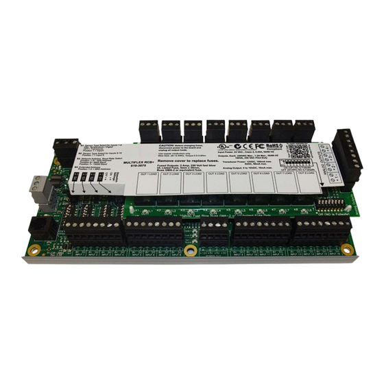
Figure 2-3 - Exploded View — MultiFlex RCB The MultiFlex RCB has an output sub-board that plugs to the top of the base board. Typically, these boards are shipped with the output board pre-installed on the board using stand- offs, so no additional hardware setup should be necessary. -
Page 8: Powering The Multiflex Rcb Board
Refer to Section 2.3.1 Choosing Transformer Sizes for center tap usage. Copeland supplies a wide variety of 24VAC transformers with varying sizes and either with or without center taps. Table 2-1 shows the transformer sizes and whether they are center-tapped or non-center-tapped. -
Page 9: Multiflex Rcb Power Wiring
2.3.2 MultiFlex RCB Power Wiring 2.3.3 Wire Types and Maximum Distances The MultiFlex RCB boards can be connected to any of the For powering I/O boards, use only the listed wire types from center-tapped transformers mentioned in Table 2-1, Table 2-3. Three-conductor non-shielded cables are the... -
Page 10: The Multiflex Rcb Battery And Battery Enable Jumper
Battery-backed memory is enabled by the ENABLE BATTERY jumper (JP5) located at the bottom right corner of the input board layer (Figure 2-7). This jumper is shipped from Copeland in the DISABLE position. The jumper should be set to the ENABLE position (UP) before installation. -
Page 11: The I/O Network
The I/O Network Although the MultiFlex RCB can operate as a stand-alone controller, it relies on an E2 unit for advanced features such as remote dial-in/dial-out, logging, and alarm control. All MultiFlex boards and controllers use an RS485 network connection to communicate with E2 site controllers. -
Page 12: Numbering The Multiflex Rcb
3.1.2.1 Numbering the MultiFlex RCB 3.1.4 Setting the Terminating Resistance Jumpers The MultiFlex RCB is a unique board type on the RS485 Network by the Copeland controllers. Each RCB that will be All MultiFlex boards and other RS485 devices have a set of... -
Page 13: Rcb Input And Output Setup
Figure 4-1 - MultiFlex RCB Input Locations The MultiFlex RCB has 16 combination analog/digital outputs for connection to all analog and digital sensors, transducers, switches, and other input types typically used in a rooftop HVAC unit application. The input type and function for each point must be programmed in the RCB software by the installer. -
Page 14: Wiring Sensors To The Multiflex Rcb
Smoke In DIG-ON/OFF Smoke alarm input for system shutdown during fire. 4.1.1 Wiring Sensors to the MultiFlex RCB 4.1.1.2 Sensor Wiring Types Specific wiring types are required for each type of sensor Wiring an input to the input points on a MultiFlex board used with E2 or RMCC. -
Page 15: Input Type Dip Switches
AC1 and AC2. This can only be done with sensors that keep the 24VAC signal isolated from its DC output signal (such as Copeland Dewpoint Probe, P/N 203-1902). If the output signal is not isolated from the 24VAC input, you must use a separate transformer. -
Page 16: The Multiflex Rcb Outputs
Figure 4-5 - MultiFlex RCB Output Locations The MultiFlex RCB has eight relay outputs for connection to all outputs that are typically present for a rooftop unit. Figure 4-5 shows the location of the RCB outputs, and Table 4-2 describes the devices that can be assigned to these points. The relay output type and function for each point must be programmed in the RCB software by the installer. -
Page 17: Wiring Outputs To Points
4.2.1 Wiring Outputs to Points The MultiFlex RCB has Form C relay contacts. Figure 4-6 shows how to wire the three-terminal Form C contact. One wire of the two-wire connection should always be connected to the middle terminal. The second wire must either be connected to the N.C. -
Page 18: Analog Outputs
Figure 4-7 - MultiFlex RCB Analog Output Locations The MultiFlex RCB analog outputs are 0-+10VDC points used for controlling variable-position economizers, mod heat and cool stages, and variable-speed fans. The maximum output current for each point is 10 milliamps. Figure 4-7 shows the location of the analog outputs. -
Page 19: Board Status Leds
ON, and unlit to show the output is OFF. The definition of ON and OFF in this case is determined by the position of the fail-safe dip switch (see Table 4-3 and Table 4-4). 026-1707 R8 MultiFlex RCB/RCB-P Manual ©2024 Copeland LP. -
Page 20: Software Overview
Introduction to Zone Control Though RCBs may be used as stand-alone rooftop unit controllers, when used with Copeland E2 BX building controllers, they may be networked together in groups called zones. Zones are groups of rooftop boards and applications (ARTC, RCBs and/or AHU (air handling units) that share the same heating, cooling, and dehumidification setpoints, as well as other control parameters. -
Page 21: Setpoints
33%, and stage 1 will deactivate when the or Cool stage ON and OFF outside of the PID control. During PID falls to 0%. dehumidification the Pulse algorithm is disabled. 026-1707 R8 MultiFlex RCB/RCB-P Manual ©2024 Copeland LP. -
Page 22: Modulating Heating And Cooling
100%. At 67%, stage 2 will come on and the modulating 100-0% 1, 2 75-50% output will drop to 0%. If the PID continues to climb to 100%, 100-0% 50-25% the modulating output will again rise to 100%. 100-0% 25-0% 026-1707 R8 MultiFlex RCB/RCB-P Manual ©2024 Copeland LP. -
Page 23: Occupied/Unoccupied Setpoints And Summer/Winter Setpoints
RCB application for both heating and cooling mode. mode (see Section 6.3, Fan Control), the RCB will use the Idle VS Fan Speed setpoint when no cooling or heating stages are active. 026-1707 R8 MultiFlex RCB/RCB-P Manual ©2024 Copeland LP. -
Page 24: Differential Vs Fan Control
If the differential is larger than the setpoint, the VS Fan speed begin dehumidification. will decrease. This will bring less air into the RTU, thus decreasing the supply air temperature and decreasing the value of the heat differential. 026-1707 R8 MultiFlex RCB/RCB-P Manual ©2024 Copeland LP. -
Page 25: Dehumidification Control
ON until the humidity rises above the cut- RCB will close the dampers. If the air is favorable for off setpoint. economization, the RCB will use the dampers like a preliminary stage of cooling, opening them first when cooling 026-1707 R8 MultiFlex RCB/RCB-P Manual ©2024 Copeland LP. -
Page 26: Operation Of Two-Position Dampers During Economization
When the smoke will be compared to the outdoor air dewpoint setpoint. If detector contact closes to indicate smoke has been the dewpoint is below the setpoint, economization will 026-1707 R8 MultiFlex RCB/RCB-P Manual ©2024 Copeland LP. -
Page 27: Priority When Economization, Co2 Control, And Smoke Detection Are Used Together
RCB will continue operating using its occupied or unoccupied heating and cooling setpoints. Dehumidification and Economization will occur during stand-alone mode only if the board is equipped with the right sensors, as described below. 026-1707 R8 MultiFlex RCB/RCB-P Manual ©2024 Copeland LP. -
Page 28: Sensor Failures
ON and OFF times. If the PlsHTFailmode or PlsCLFailmode of the heat or cool stage is set to Use Min On/Off Time, otherwise the pulse algorithm will be disabled. 026-1707 R8 MultiFlex RCB/RCB-P Manual ©2024 Copeland LP. -
Page 29: The Multiflex Rcb E2 Interface
E2 front panel. • The ability to remotely access RCBs from UltraSite32 or If you have properly set up all MultiFlex RCB boards on this Site Manager, and to back up, restore, and offline program RCB configuration along with E2 site E2’s I/O Network, you can view the status of the I/O Network... -
Page 30: Associating An Rcb With A Zone Application
Note you may choose the Zone application the controller that the MultiFlex RCB application must be configured to may be associated with. communicate with an RCB-P by setting the RCB Type Move the cursor to the AHU Zone field you wish to parameter to Pulse under the Setup screen. -
Page 31: Temperatures, Inputs, And System Status
If using Pulse Heat or Pulse Cool is ON if one Heat or Cool stage is operated in Pulse Mode, and OFF if no stages are currently being operated in Pulse Mode. 026-1707 R8 MultiFlex RCB/RCB-P Manual ©2024 Copeland LP. -
Page 32: Other Actions From The Rcb Status Screen
keys to scroll through the different screens. Press to call up the Actions Menu. Select 10. Runtime Resets from the Actions Menu. The RCB Runtime Resets screen will appear. Figure 7-7 - RCB Runtime Resets Screen 026-1707 R8 MultiFlex RCB/RCB-P Manual ©2024 Copeland LP. -
Page 33: Rcb-P Pulse Control Setpoints Setup
7.4.1 RCB-P Pulse Control Setpoints Setup To set up the MultiFlex RCB application to communicate with an RCB-P, set the RCB Type parameter to Pulse. When setting up an RCB you should go through each screen to check the function of each parameter and determine if you will need to change the value to accommodate the way you want the RCB to operate. - Page 34 COOL ACTIVE is ON for the Pulse mode stage. During Mode 2 operation (Use Min On/Off Time) of the Pulse Cool Algorithm, the compressors will always NOTE cycle at the Compressor Cycles Per Hour Calculation during the Pulse algorithm. 026-1707 R8 MultiFlex RCB/RCB-P Manual ©2024 Copeland LP.
-
Page 35: The Multiflex Rcb Hand-Held Interface
The MultiFlex RCB Hand-Held Interface The MultiFlex RCB Hand-Held Terminal interface allows you to view status of the rooftop HVAC systems and configure setpoints directly on the board. If you are using RCBs separate from a central E2 system, the Hand-Held Terminal will be the only programming interface you may use. -
Page 36: Status Menu
1 - Cool Stages 1 and 2 2 - Cool Stages 3 and 4 3 - Heat Stages 1 and 2 4 - Heat Stages 3 and 4 5 - Air Fan and Condenser Fan 026-1707 R8 MultiFlex RCB/RCB-P Manual ©2024 Copeland LP. - Page 37 1 - Cool Stages 1 and 2 2 - Cool Stages 3 and 4 3 - Heat Stages 1 and 2 4 - Heat Stages 3 and 4 5 - Air Fan and Condenser Fan 026-1707 R8 MultiFlex RCB/RCB-P Manual ©2024 Copeland LP.
- Page 38 This number should not exceed FlashErase: 3 10,000. ShutdownInp: OFF ShutdownInp shows the Shutdown Input. The Shutdown input is ON when a global shutdown is received from E2. 026-1707 R8 MultiFlex RCB/RCB-P Manual ©2024 Copeland LP.
-
Page 39: Control Menu
7. RESET - Reset device runtime totals, alarms, or reset all setpoints to Select : 5 default. 8. PID - View and/or change heating, cooling, and other PID constants. 9. MISC - General functions, including changing time and date and other setpoints. 026-1707 R8 MultiFlex RCB/RCB-P Manual ©2024 Copeland LP. -
Page 40: Control Menu - Setpoints
HtAct the RCB will energize the relay when heating mode is active. If *This screen is not available set to ClAct the RCB will energize the relay when cooling mode is on the RCB-P version. active. 026-1707 R8 MultiFlex RCB/RCB-P Manual ©2024 Copeland LP. - Page 41 HT: 01:00 01:00 typically used during heating mode to delay fan activation to prevent CL: 00:00 00:00 blowing cold air and to purge warm air from the plenum after heat stage deactivation. 026-1707 R8 MultiFlex RCB/RCB-P Manual ©2024 Copeland LP.
- Page 42 Mode - This field selects whether the fan will be controlled in Staged or Differential mode. Refer to Section 6.3.2, Variable-Speed Fan Control, for a description of these modes. 026-1707 R8 MultiFlex RCB/RCB-P Manual ©2024 Copeland LP.
- Page 43 PID percentage to a cut-in setpoint. When the economization PID is above the DigCutIn setpoint, the dampers will be OPEN. When the economization PID is below the DigCutIn setpoint, the dampers will be CLOSED. 026-1707 R8 MultiFlex RCB/RCB-P Manual ©2024 Copeland LP.
- Page 44 CL - Refers to proof inputs for all cool stages. Fan - Refers to the fan proof input. *For the RCB-P, Proofing is disabled for the heat or cool stage that is currently being operated in the Pulse mode. 026-1707 R8 MultiFlex RCB/RCB-P Manual ©2024 Copeland LP.
-
Page 45: Inputs
1-16) etc.) defaults to a type value of TEMP, indicating the sensor is a Copeland temperature sensor. However, if using LM235-based temp sensors, this field may be changed to LM-235 TMP. KW INPUT - The KW Input input type may be set to either POWER- KW (analog 0-5VDC watt transducer) or PULSE-CNT (pulse accumulation type KWH input). -
Page 46: Scheduling
“.” to “-” to toggle to YES. Advance to override value and enter the Ovrd Value: 77 desired value. To cancel the override, arrow to the YES field and toggle to NO. 026-1707 R8 MultiFlex RCB/RCB-P Manual ©2024 Copeland LP. -
Page 47: Resets
HHT is plugged into the RCB. When the HHT is removed, the E2 will rewrite its stored configuration to this RCB. Resetting setpoints from the HHT does NOT affect this RCB’s configuration in the E2. 026-1707 R8 MultiFlex RCB/RCB-P Manual ©2024 Copeland LP. -
Page 48: Pid
The values chosen by default for the PID constants are the recommended settings for use in HVAC control. It is not recommended you alter these values without assistance from Copeland. I: The I field is the PID’s integral gain. This is a multiplier that affects the... -
Page 49: Miscellaneous
KWPerPulse - If using a pulse accumulator style KW transducer, this parameter sets the number of KW represented by each pulse. Refer to your transducer’s specifications for the correct value, and enter it in this field. 026-1707 R8 MultiFlex RCB/RCB-P Manual ©2024 Copeland LP. -
Page 50: Daylight Savings
(5th) Sunday of October. If you wish to choose different start DLT Savings End months, weeks, or days, enter them on this screen. OCT 5thWeek SUN This screen is not available on the RCB-P version. 026-1707 R8 MultiFlex RCB/RCB-P Manual ©2024 Copeland LP. -
Page 51: Index
10 8IO Combination Input/Output Board input type dip switches 10 Heat Differential 19 power connections for sensors 10 Heating 17 HHT interface. See MultiFlex RCB, HHT interface. Humidification control 19, 20 ARTC dehumidification during stand-alone 22 I/O Network... - Page 52 Software overview 15 stand-alone operation 22 dehumidification control 19 status LEDs 14 fan control 18 temperature control 15 Humidification control 19 MultiFlex RCB-P (Pulse) Board 1 outside air control 20 reversing valve wiring 22 sensor failures 23 Network humidity 23 RS485 I/O...
- Page 53 22 other operation 22 summer/winter scheduling 22 temperature control 15 zone control 15 Staged Cooling 17 Staged Heating 17 Status LEDs. See LEDs. Termination Resistance Jumpers, I/O Network. See Jumpers, Termination. 026-1707 R8 MultiFlex RCB/RCB-P Manual ©2024 Copeland LP.
- Page 54 The contents of this publication are presented for informational purposes only and they are not to be construed as warranties or guarantees, express or implied, regarding the products or services described herein or their use or applicability. Copeland reserves the right to modify the designs or specifications of such products at any time without notice.
Need help?
Do you have a question about the MultiFlex RCB and is the answer not in the manual?
Questions and answers