Table of Contents
Advertisement
Quick Links
Advertisement
Table of Contents

Related Manuals for HELI gleen DSGO5C16


Summary of Contents for HELI gleen DSGO5C16
- Page 2 FORWARD CQD AC type electric reach truck is the new offering of HELI to meet the needs of the market. The new series is designed on the base of the advantages of some reach trucks made by domestic and foreign manufacturers and developed by introduced technology from abroad.
-
Page 3: Table Of Contents
CONTENTS FORWARD I. Safety Instructions of Operation and Driving.............2 II. External View of Reach Truck ..................6 III. Main Specifications ....................7 IV. Construction and Principle of Reach Truck .............8 4.1 Transmission system ..................8 4.1.1 Drive motor shaft ..................8 4.1.2 Input shaft ....................8 4.1.3 Drive shaft....................8 4.1.4 Drive wheel installation ……………………………………………. -
Page 4: Safety Instructions Of Operation And Driving
I. Safety Instructions of Operation and Driving 1. Drivers and equipment keepers should keep “safety first” in mind and operate according to the operation and service manual. 2. Transporting Pay attention to the following instructions before transporting the forklift with containers or trucks: 2.1 Take the mast backward, turn off the battery and pull the parking brake. - Page 5 Fig. 1-1 (1)LCD (2)Key switch (3)Lifting and lowering lever (4)Reach lever (5)Tilting lever (6)Side shifter lever (7)Direction switch (8)Horn (9)Emergency switch (10)Hand wheel (11)Electric pedal (12)Brake pedal 4.6 Check all of the connectors and plugs in the electric system for reliable contact and accelerator pedal for effectiveness and flexibility.
- Page 6 5.3 Turn on the key switch and pull up the emergency switch, set the direction to the desired position, depress the accelerator pedal gradually and keep suitable acceleration. 5.4 Read the electric energy on the meter and charge the battery or change a full one when the capacity of the battery is less than one LED.
- Page 7 6. Charging 6.1 Obey the stipulations strictly in operation instruction for battery when first charging or recharging. 6.2 if the output voltage of the battery is reduced to 41V or the voltage of anyone lower than 1.7V or the meter alarms, the truck should stop working immediately until the battery is replaced or charged.
-
Page 8: External View Of Reach Truck
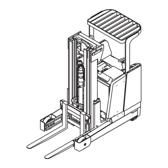
II. External View of Reach Truck Fig. 2-1 External View of Reach Truck... -
Page 9: Main Specifications
III. Main Specifications Item Parameter Characteristics Rated capacity 1600 2000 Load center Lifting height 4250 4250 Free lifting height 1370 1370 Lifting speed(loaded) mm/s Travel speed km/h 10/11 10/11 (loaded/unload) Reach distance Climbing ability 10/15 10/15 (loaded/unload) Tilt angle(F/R) ° Turning radius 1700 1780... -
Page 10: Construction And Principle Of Reach Truck
IV. Construction and Principle of Reach Truck 4.1 Transmission system Transmission type Continuous speed control Forward 1:17.96 Velocity ratio Reverse 1:17.96 Drive wheel 343×114 ( diameter×width) Weight 35kg Volume of oil 3.7L Type of oil 85W/90 The transmission system of reach truck is gear assembly (seeFig. 4-1). Drive wheel is fixed on the flange of the drive shaft by way of hub nut and hub bolt. -
Page 11: Drive Wheel Installation
of bevel gear is adjusted by two groups of shim. The clearance is 0.18-0.23mm. 4.1.4 Drive wheel installation (1) Drive wheel Demounting a) Put the rear part of the forklift on and stop the front with padding block. b) Turn the hand wheel to make the side of the drive wheel towards the rear part. c) Remove the nuts from the drive wheel. - Page 12 Fig.4-1 Clutch Type Transmission (1) Drive wheel (2) Hub bolt (3) Hub nut (4) Shim (5) Snap ring (6) Roller bearing (7) Bevel gear (8) Snap ring (9) Oil seal (10) Shim (11) Drive shaft (12) Spacer (13) Nut (14) Roller bearing (15) Oil seal (16) O-ring (17) Shaft (18) Roller bearing (19) Shim (20) Spacer (21) Shim (22) Roller bearing (23) Driven gear (24) Locking nut (25) Coupling chassis (26) Bearing support (27) O-ring (28) Roller...
-
Page 13: Steering System
4.2 Steering system Model of steering system Electric power trailing rear wheel steering Steering motor 48V 0.6kW 2275rpm Steering gear decelerate ratio 1:25.83 Chain drive decelerate ratio 1:5.88 Control model Diameter of hand wheel 200mm The steering system consists of a steering column assembly, a steering control, a steering motor, a steering gearbox, a sprocket wheel, a chain and a switch. - Page 14 Fig. 4-2-1 Steering Column Assembly (1) Sensor (2) Securing plate (3) Bracket (4) Coupling (5) Connection shaft (6) Bearing (7) Snap ring (8) Friction ring (9) Spring (10) Bond (11) Washer (12) Nut (13) Front cover (14) Rear cover (15) Bond (16) Hand wheel (17) Washer (18) Nut (19) Space generator (20) Bracket (21) Washer (22) Washer (23) Bolt (24) Nut...
-
Page 15: Steering Gearbox
Fig. 4-2-2 Steering Gearbox (1) Chain assembly (2) Steering motor (3) O-ring (4) Upper cover (5) Lower cover (6) Drive gear (7) Ball bearing (8) Ball bearing (9) Drive shaft (10) Output gear (11) Output shaft (12) Ball bearing (13) Switch (14) Snap ring (15) Feedback shaft (16) Ball bearing (17) Feedback gear (18) Ball bearing (19) Oil seal (20) Ball bearing (21) Oil seal (22) Bond (23) Chain (24) Snap ring (25) Sensor plate assembly... -
Page 16: Spare Steering System
and the feedback shaft is fixed on the case through two ball bearings, Oil seal prevents lubrication grease from flowing away. 4.2.3 Spare steering system The truck has a spare steering system in case of an electric failure or that the truck doesn’t been dragged. - Page 17 The brake system (hydraulic) consists of the front two-wheel braking type and the real wheel (with braking force restrictor) motor braking type. It is made up of master cylinder, brake, braking force restrictor and brake pedal mechanism. (1) Master cylinder The master cylinder contains valve support, check valve, return spring, primary cup, piston and secondary cup, which are all kept in place with a stop washer and a stop wire.
- Page 18 Fig. 4-3-1 Master Cylinder (1) Cylinder body (2) Spring (3) Seal ring assembly (4) Primary cup (5) Protecting cover (6) Piston (7) Secondary cup (8) Washer (9) Snap ring (10) Dust cover (11) Push rod and supporting ear (12) Check valve (13) Primary cup (14) Joint (2) Brake Brake is distributed to wheel brake and driving motor brake.
- Page 19 Fig. 4-3-2 Wheel Brake (1) Brake shoe assembly (2) Floor plate (3) Operating cylinder (4) Spring (5) Clearance plate (6) Return spring (7) Push plate (8) Anchor pin (9) Stop ring (10) Spring support (11) Brake shoe (12) Clearance spring (13) Spring (3) Brake force restrictor Brake force restrictor consists of cylinder body, piston, spring, cup, bushing,...
-
Page 20: Parking Brake
(4) Brake pedal adjustment a) Make the push rod shorter. b) Adjust the pedal to the height of 120mm. c) Press the pedal for 30-40mm and adjust the push rod until the front end of the push rod get in contact with the master cylinder. d) Tighten the push rod lock nut. - Page 21 rod. So the driving motor axle can not run. And the forklift can not start up. Push the hand brake before the truck starts to work. At the same time, the inching switch under the instrument panel assembly loosens, the brake mood on the meter shows loosening, and the truck can start.
-
Page 22: Hydraulic System
4.4 Hydraulic system Model DSGO5C16 Type Gear pump Drive Electromotor export Lift pump Displacement 16ml/r Output pressure 200bar Highest pressure 250bar Temperature range -20℃-80℃ Model With relief valve and tilt Control valve Type lock valve Pressure setting 145bar(1.6t)175bar(2t) Type Plunger Front lift cylinder Diameter of piston 65mm... -
Page 23: Operation Of Control Valve
Fig. 4-4-1 Control Valve The control valve(4 spools type0 consists of six valve housings, four spools, one relief valve. The self lock valve is installed in tilt spool. (1) Mater relief valve The valve consists of main valve and pilot valve. It can limited the pressure of the system. - Page 24 together with a shaft and the shaft is assembled on the front guard with the bracket. The valve levers operate the control valve with the joints. Operating the lift valve will change the voltage of the potentiometer, and the operating will transfer the signal to lift controller. Operating other levers and the valve switch will inspect the signal and transfer it to lifting controller.
-
Page 25: Hydraulic Pipeline System
Fig. 4-4-3 4.4.4 Hydraulic pipeline system Hydraulic pipeline system (Fig. 4-4-4) Hydraulic pipeline system is a single pump system. The system consists of four pipelines, every one pipeline control relevant action. (1) Pipelines for mast rising and falling down a) Pipeline for mast rising (the direction of hydraulic oil) Pump--control valve--cut off valve—SB valve—front cylinder—rear cylinder b) Pipeline for mast falling down (the direction of hydraulic oil) Rear cylinder—front cylinder—SB valve—cut off valve—flow regulator—oil... - Page 26 (3) Pipeline for mast reaching (the direction of hydraulic oil) Pump—control valve—reach cylinder (4) Pipeline for lifting bracket shifting (the direction of hydraulic oil) Pump—control valve—side shifting cylinder Fig. 4-4-4 Hydraulic Pipeline System...
-
Page 27: Rear Lifting Cylinder
4.4.5 Rear lifting cylinder The two rear lifting cylinder is fixed inside of the outer mast. The bottom of the cylinder is fixed on the under cross beam of the outer mast by bolt while the top of the cylinder is connected with the upper cross bean by stretch clip. The strokes of the two cylinder should be synchronous during the lifting and falling down. - Page 28 Fig. 4-4-5 Rear Lift Cylinder (1) Dust seal (2) Yx ring (3) Bolt (4) Shim (5) O-ring (6) Cylinder cap (7) Cylinder body (8) Stretch ring (9) Piston rod (10) Support ring (11) Valve core (12) Spring (13) Bushing (14) Spring seat (15) O-ring (16) Seat (17) Cylinder body There is a buffering valve at the bottom of the cylinder to avoid the impact caused by the mast falling.
-
Page 29: Front Lift Cylinder (Fig. 4-4-6)
4.4.6 Front lift cylinder (Fig. 4-4-6) The bottom of the oil cylinder is fitted to the cylinder fixing hole in the lower cross bean and it is held by the pin. The top of the cylinder is connected to the chain in order to connect with the lifting chain and the pipes and is fixed by stretch clip. -
Page 30: Tilt Cylinder (Fig. 4-4-7)
Fig. 4-4-6 Front Lift Cylinder (1) Piston rod (2) Dust seal (3) Yx seal (4) Screw (5) Shim (6) O-ring (7) Cylinder cap (8) Bushing (9) Screw (10) Snap ring (11) Joint bushing (12) Cylinder body (13) Bolt (14) Piston (15) Support ring (16) Spring (17) Flow regulator (18) Cut-off valve (19) O-ring 4.4.7 Tilt cylinder (Fig. -
Page 31: Reach Cylinder
Fig. 4-4-7 (1) Bearing (2) Snap ring (3) Bearing (4) Washer (5) Nut (6) Piston rod assembly (7) Dust seal (8) Snap flake (9) Yx seal (10) Guide sleeve (11) O-ring (12) Bearing (13) Cylinder assembly (14) Support ring (15) Snap flake (16) Yx seal (17) Bearing (18) Cup When the tilt cylinder is pushed forward, the control valve will change direction and the high pressure oil flows from the cylinder bottom to push the piston rod forward. -
Page 32: Loading System
ring and two Yx seals. A bearing with Yx-ring, snap ring and dust seal is pressed into the hole in the guide sleeve. The bearing is used to support the piston rod and the seals and snap ring are used to prevent oil leakage and keep dust off. The guide sleeve is screwed into the cylinder body. - Page 33 rollers to make the inner and middle masts move up and down stably. Fig.4-5-1 The Shape of Mast Cross Section Roller: Main roller φ88.8 Side roller φ40 Lifting: Rear cylinder chain LH1244 Front cylinder chain LH1288 Fork, mast lifting system hydraulic Lift bracket, side shifter hydraulic Fork spacing adjustment...
- Page 34 Reach truck with the function of the triple full lift have more superiority comparing with common reach trucks. The truck can lift the loads to the height of the forklift truck with the whole height of the forklift truck unchanged. Thus the truck can handle, stack loads with the whole height unchanged.
-
Page 35: Side Shifter (Fig. 4-5-2)
4.5.2 Side shifter (Fig. 4-5-2) Fig. 4-5-2 The side shifter is made up of side shifter bracket, fork bracket, side shift cylinder and so on. The side shifter bracket is of welded structure. Side shifter can move up and down smoothly along the inner mast and bear the vertical and horizon load through three pairs of main roller and two pairs of side roller which can adjust clearance. -
Page 36: The Adjustment Of Loading System
Fig.4-5-3 Side Shift Cylinder (1) Dust seal (2) Yx seals (3) Cylinder cover (4) Screw (5) Washer (6) Washer (7) O-ring (8) Side shift cylinder staff (9) Side shift cylinder body (10) Snap ring (11) Snap ring (12) Snap ring 4.5.3 The adjustment of loading system (1) Make the mast be vertical and drop the fork to the ground. - Page 37 speed reduction switch, traction control module, AC traction motor; Lift control system consists of valve control switch, lift speed adjust sensor, lift control module, AC pump motor; Steering control system consists of motor (sending out instruction signal), turn angle switch (feeding back turn angle position signal), automatic centering switch, steering control module, AC steering motor.
- Page 38 Fig.4-6-1 Electric System Principle Diagram...
-
Page 39: Detail Description Of Electric System
4.6.2 Detail description of electric system 4.6.2.1 CAN bus technology CQD16/20 AC type electric reach truck applies the CAN bus technology. It links with each CAN module (traction control module, lift control module, steering control module, instruments display module) and acts as a connection point between the outside equipments and the CAN bus. - Page 40 Fig.4-6-2 a) The six buttons fixed in the bottom of the display are used to enter the display menu structure. (Only in the case of permission) Button 5---the function of the “OUT” button in the hand manual; Button 4--- the function of the “SET DOWN” button in the hand manual; Button 3--- the function of the “SET UP”...
- Page 41 b) After the self-check, it will display the changeable steering angle. (Replace the total traction hours) Fig. 4-6-4 c) Display of safe and brake: the truck is on a state of brake when loosen the safe pedal. The truck can not drive but it can steer, lift, tilt mast and move mast. The picture is on all the time.
- Page 42 Fig. 4-6-6 (4) Instrument working environment a) The height above the sea lever should be less than 1200m. b) The temperature should be in the range of -25℃-40 . ℃ c) The maximize relative humility should be less then 95%. 4.6.2.3 Controller system instruction CQD16/20-GA2S AC type electric reach truck is assembled with two Italy ZAPI motor controller.
- Page 43 Fig. 4-6-8 Steering Controller of the CQD16/20 Electric Reach Truck (1) Traction and pump motor controller Traction motor controller type: ZAPI COMBIAC2 48V/450A ● COMBIAC2 controller is a three phase AC type asynchronous motor inverter, which controls traction motor and pump motor. It has a CAN BUS interface, digital control of micro processor (feed back of the motor speed), and regeneration function.
- Page 44 convenient to maintain the system. (2) Steering motor controller a) CQD16/20 AC type electric reach truck applies advanced electric power steering control system. It is assembled with Italy EPS-ACO controller. Steering motor control type: ZAPI EPS-ACO 48/45A ● EPS-ACO controller applies high-frequency MOS technology. The control is not only reliable but also efficient, low cost, smooth and mute.
- Page 45 that case there will be no danger even the connection is in error. ◆ A certain amount of voltage will remain in filter capacitance after the turn off of the electric switch. Cut off the battery and make the remained voltage short circuit by connecting the 10-100ohm resistance to the inverter before checking the inverter.
- Page 46 Fig. 4-6-9 Battery Construction Note: Battery can be customized. (2) The usage of battery The usage and routine maintenance of the battery will influent battery life and performance. So the operator should maintain the battery according to the manual and actual conditions.
- Page 47 f) The electrolytic lever will decrease and the density will increase as the evaporation and electrosis of the water in the electrolytic when charging. Add the distilled water regularly to keep the electrolytic lever and density. g) Avoid over charging and over use of the battery which will affects the battery life.
- Page 48 c) Do not charge the battery in low temperature (such as cold outside) which will affects the battery life. Note: ● The rated voltage of the battery is not the safe voltage. Look out for a electric shock. ● The battery is lead acid battery which electrolytic is dilute sulfate. Wear protection tools when testing, adding and adjusting to avoid accidents.
- Page 49 9)Impure impurity should be electrolytic in the prescribed Inside short range. circuit or electric leakage 1) low battery voltage or close to zero indeed when charging 2) few or no air bubble at 1) curve pole plate; the end of the charging expanded reactive Replace high...
-
Page 50: Diagnosis
4.6.3 Diagnosis 4.6.3.1 General instruction The traction control system, loading control system, steering control system and intelligent instrument system assembled in the truck are continually monitoring micro-processor controller. They all have a diagnosis program to a main function. The program includes the following point: .(1) diagnosis when the electric lock being off: the circuit of the watching dog, current censor, charging of the capacity, phase voltage, driving of the connector, can-bus connector, the order of the switch operation, the output of the acceleration, the... - Page 51 and make the traction require in force LOGIC Exclude the faults Overload FAILU and make the protection of the RE#3 traction require in hardware circuit force The fault of the Exclude the faults LOGIC feedback circuit and make the FAILT of U,V,W phase traction require in URE#2...
- Page 52 capacity when the electric being off; the faults of the power assessment or PCB plate of the logic card or the driving PCB card or motor Exclude the fault and the alarm will disappear if in the DRIVE The short circuit initializing state;...
- Page 53 CLOSE the main electric lock contactor when off-working. Exclude the faults CONT when working; Poor connect of ACTO reclose the the main electric lock contactor OPEN when off-working. ENCO Abnormal of the Reclose the motor speed ERRO electric lock sensor (encoder) Exclude the faults PEDAL The fault of the...
- Page 54 micro-processor through CANBUS Exclude the fault and the alarm will The short circuit disappear if in the or broken way initializing state; OUTP if in other states, UT KO electromagnetic exclude the faults brake coil and make the traction require in force The fault of the EEPRR...
- Page 55 WARD input signal The traction or THER lifting controller Exclude the fault temperature and the alarm will SENSO sensor exceeds disappear R KO its range. The lifting WAITI processor is on Exclude the fault alert state and the alarm will displayed in NODE disappear...
- Page 56 set min. voltage 4.6.3.3 The fault code of EPS-ACO inverter Glimmer Fault Description in The condition description ing times code the hand manual of excluding the faults A disparity between the MICRO SLAVE controller and the walking and Change the chopper steering motors A disparity of rotation direction MICRO...
- Page 57 principle processor is off checked by subordinate controller. But it is on. The safe switch inside the subordinate processor turns off Find the causes or KS CLOSED before receiving the order Change the chopper which is checked by principle processor. The safe switch inside the subordinate processor is on KS OPEN...
- Page 58 OPEN connect, which is checked by making the main controller. contactor open circuit in the traction control. Check the CAN BUS CAN BUS KO No communication line The steering motor’s current MOTOR Check whether the closes to the motor’s maximize LOCKED motor seizures or not.
- Page 59 steering motor. A disparity between the STEPPER frequency and the amplitude of Change the chopper MOTOR MISM the walking motor. A disparity between the ENCODER Change the second encoder frequency and the ERROR channel of the encoder. order frequency EEPROM KO A failure of EPROM writing Change the chopper.
- Page 60 of shutting off the safety switch. There is a disparity between the data from the processor’s EPS NOT diagnosis and the set one. Cut ALIGNED the steering and traction after 6 seconds. 4.6.3.4 Fault code on the intelligent instrument Code Fault name code Fault name...
- Page 61 NO FULL COND STEER SENSOR KO RGT NO FULL COND STEER HAZARO LFT NO FULL COND PEDAL WIRE KO PU NO FULL COND PEDAL FAILURE CONNECTOR CLOSED TRACYION BRUSHES CONNECTOR OPEN PUMP BRUSHES BRAKE CON. CLOSED DRIVER 1 KO BRAKE CONT. OPEN DRIVER 2 KO DIR CONT.
- Page 62 “COIL SHORTED” A short circuit occurs in a load which connects to the power output (A19 and A20). So the relative drivers generate big current the following can be done: ---.Check whether the load is broken or shot circuit or not. --- Check the relative circuit --- If the fault still exists when the load connective circuit is open, it is probably the broken of the big current protective circuit of the display.
-
Page 63: Routine Maintenance
“BRUSHES” The electric brush wear sensor of the lifting motor sends out a signal of wear. The following can be done to solve the fault: Check whether the relative digital input point (A5) is effective. (To teser menu). Check the effective lever type of the input point (+VB or GND). (To SET OPTIONS menu): --- If the fault exists when the input point is effective, check the wear of the electric brush, circuit and the electric brush wear sensor;... -
Page 64: Battery Moving
the content of this manual. Any cause which is visible or reliable by an ordinary technician who periodically checks the equipment, which can create damage or defects to the device, should be transferred to our company. 4.6.5 Battery moving (1) Take out the battery Draw the valve’s reach lever back, and take the mast back as it will. - Page 65 Fig. 4-6-10 The System for Separating the Battery Rack (1) Knob (2) Washer (3) Bolt M8×40 (4) Lever (5) Bracket (6) The lock system (7) Bolt M6×12 (8) Bolt M6×20 (9) Cupreous gasket (10) Washer (11) Washer...
-
Page 66: Supporting Wheel
Fig. 4-6-11 The Hook and Lock Assembly (1) Hook and lock assembly (2)Washer (3) Nut M16 (4)The extending spring When the locking system does not work, separate the hook and pillar by hand, then draw the reach lever. And the battery can be taken out. 4.7 Supporting wheel It has three points supporting the reach truck, and two of them are in the front distributing in symmetry, (To fig. - Page 67 should be fixed with a great deal of lubricating before the supporting wheels installation. It should be replacing by a regulate periods. (Every two months) Fig. 4-7 Supporting Wheel (1) Wheel (2) Brake drum (3) Bolt (4) The fastness bolt (5) The axis (6) Bearing (7) Backstop...
-
Page 68: Troubleshooting
V. Troubleshooting 5.1 Transmission system Problem Possible cause Remedies 1)Too much clearance Adjust between the gears Loud noise of gears when 2) Much wear of the gears Replace driving 3) Lower oil lever in oil Add oil tank 1)Too much clearance Loud striking noise when Adjust... - Page 69 2) Gas existing in the Exhaust gas pipeline 3) Poor clearance adjustment of the brake Adjust shoe 4) Over heat of the brake Check and repair 5) Poor adjustment of the adjust brake pedal 1) Dirty existing in the Check and repair friction surface 2) Torn out or incorrect fix Check and repair...
- Page 70 6) Poor adjustment of the Adjust knob 5.5 Electric system Problem Possible cause Remedies 1) Poor contact of the key Check and repair switch 2) Broken wire Connect again No signal after the turning 3) Poor contact of the on of the key switch Check and repair connector 4) Poor connection of the...
-
Page 71: Maintenance
VI. Maintenance 6.1 Routine maintenance In the use of the work, especially during the first operation period of the new truck, carefully operation and timely adjustment, maintenance and service are all necessary for keeping the truck in good condition. Do as the following. (1) When a new truck has been used for 100 hours, replace the gear oil in differential and main reducer, and tighten all fixing parts. - Page 72 lubricating grease Hydraulic oil 1000h Clean tank and filter Hydraulic oil Replace 1000h 3000h Replace it at Lift chain Replace once when damaged 3000h Replace it at High pressure Replace once when pipe damaged 6.2 Oil for forklift truck Trademark/code Trademark/code Name name(home)
- Page 73 6.3 Lubricating chart...
-
Page 74: Others
VII. Others 7.1 The size and weight of the main takedown parts of the truck Type Unit CQD16 CQD20 Parameter Max. figure size 700×1100×995 700×1170×995 Overhead guard Weight Max. figure size 1070×100×40 1200×125×50 Fork Weight Mast Max. figure size 2010×304×735 (lift height Weight 4250mm) - Page 75 7.2 Mast breakout Reaching forward and tilt backward the mast, hook in the swing position of the mast with a cord; dismantle three high pressure hose in the bottom of the mast and the pin installed in the tilt cylinder. Loose the bolt(M16×8)in the outer mast’s cap, and take off the cap, and then the mast can be dismantled from the truck body.
- Page 76 Product : Electric Reach Truck Type Designation /Trademark : CQD16, CQD20 Manufacturers Name : Anhui Heli Co., Ltd. Manufacturers Address : 163 Woyun Road, Hefei City, Anhui Province, P.R. China Refer to in this declaration conforms to the following directive(s):...
Need help?
Do you have a question about the gleen DSGO5C16 and is the answer not in the manual?
Questions and answers