
Related Manuals for Sorensen XT Series


Summary of Contents for Sorensen XT Series
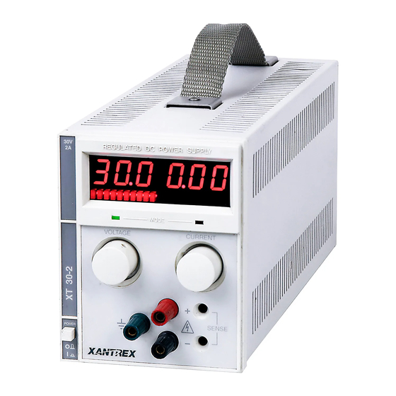
- Page 1 sales@artisantg.com artisantg.com (217) 352-9330 | Visit our website - Click HERE...
- Page 2 Instruction Manual Instruction Manual for Internal GPIB Interface for XT and HPD Series Power Supplies TM-9BGP-6HSN...
- Page 3 ©Copyright 1997 Not to be copied in part or in full. Printed in Canada...
-
Page 4: About This Manual
ABOUT THIS MANUAL GPIB INTERFACE ABOUT THIS MANUAL This is the technical manual for the GPIB Interface, a microprocessor-controlled option card installed inside your XT (60 watts) or HPD (300 watts) Series DC output power supply. This manual provides you with descriptions and specifications, user options, and configuration instructions, in addition to a command set which will enable you to manage your power supply from an external source. -
Page 5: Manual Changes
MANUAL CHANGES GPIB INTERFACE MANUAL CHANGES There are no changes or additions at this time. Release 2.1 (2001/06) -
Page 6: Table Of Contents
GPIB INTERFACE CONTENTS CONTENTS About This Manual............................i Manual Changes ............................ii Contents............................... iii List of Figures ............................. v List of Tables............................... v 1. FEATURES AND SPECIFICATIONS 1.1 Introduction to the GPIB Interface ....................1-1 1.2 Features and Functions ........................1-2 2. - Page 7 CONTENTS GPIB INTERFACE 4. CALIBRATION 4.1 Introduction............................4-1 4.2 Voltage Mode Calibration ......................4-1 4.2.1 Voltage Calibration Setup....................4-1 4.2.2 Voltage Program Calibration Procedure................4-1 4.2.3 Voltage Readback Calibration Procedure................4-2 4.3 Current Mode Calibration......................4-3 4.3.1 Current Calibration Setup ....................4-3 4.3.2 Current Program Calibration Procedure ................4-3 4.3.3 Current Readback Calibration Procedure ................4-4 4.4 Over Voltage Protection (OVP) Calibration..................4-4 5.
- Page 8 GPIB INTERFACE CONTENTS LIST OF FIGURES Figure 1.1-1 Sample Configuration using GPIB Interface ................1-1 Figure 2.2-1 Power Supply Front Panel (GPIB Interface Installed)............2-2 Figure 2.2-2 Power Supply Rear Panel (GPIB Interface Installed)............. 2-2 Figure 2.2-3 GPIB Interface PCB for 60W and 300W Series Supplies ............2-3 Figure 2.4-1 J7 User Cable with Ferrite Block....................
-
Page 9: Features And Specifications
GPIB INTERFACE DESCRIPTION FEATURES AND SPECIFICATIONS Introduction to the GPIB Interface The Internal GPIB Interface card allows you to operate your power supply from a computer controller via the IEEE-488 communications bus. This interface is used with the 60 watt and 300 watt series DC power supplies. Figure 1.1-1 shows a sample configuration using the GPIB interface. -
Page 10: Features And Functions
DESCRIPTION GPIB INTERFACE Features and Functions Features • 16-bit programming and readback of voltage and current • Programmable soft limits for voltage and current • Programmable overvoltage protection with reset • Easy-to-use, self-documenting command set • Isolated user-programmable signals such as fault, polarity, isolation, and auxiliary signals. •... -
Page 11: Installation And Configuration
GPIB INTERFACE INSTALLATION AND CONFIGURATION INSTALLATION AND CONFIGURATION Introduction To use this product, you must have the following equipment: • 60 Watt or 300 Watt variable DC output power supply • IEEE-488 connector and cable • Digital controller with an IEEE-488 interface •... -
Page 12: Figure 2.2-1 Power Supply Front Panel (Gpib Interface Installed)
INSTALLATION AND CONFIGURATION GPIB INTERFACE Remote Mode (REM) LED Service Request (SRQ) LED Over Voltage Protection (OVP) LED OVP Potentiometer Figure 2.2-1 Power Supply Front Panel (GPIB Interface Installed) (60 watt supply shown) Error (ERR) LED SW1 Switch: Addressed (ADR) LED 1 Remote Mode Selection 2 Power ON Request (PON SRQ) Selection... -
Page 13: Jumper Selection
GPIB INTERFACE INSTALLATION AND CONFIGURATION CAUTION Use proper static control techniques to avoid damage to static-sensitive components on the printed circuit board. JUMPER SELECTION Local Mode Disable Selection [closed [default] See Section 2.3.3 [open] Software control of power supply only. See Section 2.3.3 J117 User Shutdown... -
Page 14: Basic Setup Procedure
INSTALLATION AND CONFIGURATION GPIB INTERFACE Basic Setup Procedure This procedure can be used as a quick reference for those familiar with the configuration requirements for the GPIB Interface. For those who want more information, each step refers to more detailed procedures located in subsequent sections. -
Page 15: Ieee-488 Primary Address Selection
GPIB INTERFACE INSTALLATION AND CONFIGURATION 2.3.1 OVP Selection CAUTION If you remove the unit's cover, use proper static control techniques to avoid damage to static-sensitive components on the printed circuit board. Over voltage protection (OVP) on the GPIB Interface is set at the factory for remote software operation. When operating the power supply in remote mode, you control the OVP trip level using the OVSET software command. -
Page 16: Remote/Local Operation
INSTALLATION AND CONFIGURATION GPIB INTERFACE 2.3.3 Remote/Local Operation You can enable or disable remote or local operation of your power supply in one of four ways: • Rear panel Remote/Local switch SW1-1, or • IEEE-488 Local Lockout command, or • Device-dependent LOC command, or •... -
Page 17: Table 2.3-6 Local Mode Disable Jumper J95
GPIB INTERFACE INSTALLATION AND CONFIGURATION 2.3.3 Remote/Local Operation (continued) LOC Command The LOC command overrides the Local Lockout command which in turn overrides the Remote/Local switch. Use LOC to enable or disable one or all slave supplies to operate in local mode. See Section 3.5 Command Reference. -
Page 18: Ieee-488 Controller Connection
INSTALLATION AND CONFIGURATION GPIB INTERFACE 2.3.4 IEEE-488 Controller Connection CAUTION Do not operate power supplies at different chassis potentials. The interface connection system is not capable of handling the resulting excessive ground currents. Use an approved IEEE-488 connector and cable when connecting the GPIB Interface to your IEEE-488 GPIB network. -
Page 19: J7 Cable Connection
GPIB INTERFACE INSTALLATION AND CONFIGURATION 2.4.2 J7 Cable Connection Use a standard 8-position telephone jack and data cable to connect to J7. Add a ferrite block to reduce radiated emission. The one inch square ferrite block with built-in housing clip is packaged and shipped with the power supply interface card. -
Page 20: Operation
GPIB INTERFACE OPERATION OPERATION Introduction This section covers GPIB Interface programming, starting with IEEE-488 functions, continuing with an extensive set of device-dependent commands, and, finally, providing error codes, and status and fault register information. GPIB Operation A GPIB interface controller card enables you to control an IEEE-488 bus system via computer, identifying which of its interconnected devices are to send and receive data. -
Page 21: Device Clear
OPERATION GPIB INTERFACE 3.2.2 Device Clear The power supply will implement Device Clear regardless of whether it is in local or remote control. Device Clear is typically used to send all or selected devices to a known state with a single command. The power supply will be set to Initial (Power On) Conditions after Device Clear. -
Page 22: Power On Service Request (Pon Srq)
GPIB INTERFACE OPERATION 3.2.6 Service Request Service request is a uniline message asserted by the power supply at power on and for fault conditions. Six (6) power supply conditions are defined as faults. See Section 3.6 Accumulated Status, Status, and Fault Registers for more information about CV, CC, OV, SD, ERR, and FOLD. -
Page 23: Command Syntax
OPERATION GPIB INTERFACE Command Syntax 3.3.1 Command Format and Parameters Format: COMMAND <parameter> or COMMAND <parameter>,<parameter> Table 3.3-1 Command Parameters Explanation Examples/References <current> <float> plus A (amps; default) or mA (milliamps) <fault mask> a combination of CV, CC, OV, SD, and/or FOLD. See MASK and UNMASK commands in Section 3.5 Command Reference. -
Page 24: Command Strings
GPIB INTERFACE OPERATION 3.3.2 Command Strings If you send more than one command per line, separate the commands with a semicolon. The semicolon may be preceded or followed by spaces. Example: ISET 2.0A;VSET 5 or ISET 2.0A ; VSET 5V 3.3.3 Command Terminators Terminators indicate the end of a command string and tell the power supply to execute the command. -
Page 25: Command Summary
OPERATION GPIB INTERFACE Command Summary Use these commands to control the operation of the supply. They are listed here in order of function such as PROGRAMMING, QUERY, CALIBRATION, and STATUS commands. See Section 3.5 Command Reference for more detailed information about each command and its use. Table 3.4-1 Programming Commands Command Description... -
Page 26: Table 3.4-3 Calibration Commands
GPIB INTERFACE OPERATION Table 3.4-3 Query Commands (continued) Command Description Queries the present enabled/disabled status of the IEEE-488 Service Requests SRQ? generated by the supply. VMAX? Queries the soft voltage limit setting for the supply. VOUT? Measures the actual voltage output for the supply. VSET? Queries the present output voltage setting for the power supply. -
Page 27: Command Reference
OPERATION GPIB INTERFACE Command Reference Table 3.5-1 Command Reference Command Description Queries the accumulated status for the supply. The accumulated status ASTS? register stores any bit that was entered in the status register since the accumulated status query command (ASTS?) was last used (if at all), regardless of whether the condition still exists. - Page 28 GPIB INTERFACE OPERATION Table 3.5-1 Command Reference (continued) Command Description FAULT? Queries the fault register for the supply's fault condition status. When a bit is set in the fault register, the rear panel J7 connector Fault Line 4 is also asserted.
- Page 29 OPERATION GPIB INTERFACE Table 3.5-1 Command Reference (continued) Command Description IMAX <current> Sets an upper soft limit on the programmed output current for the supply. If the soft limit is exceeded, or if the soft limit value is lower than the present output current setting, the supply will ignore the command, turn on the ERR LED, and set the ERR bit in the status and serial poll registers.
- Page 30 GPIB INTERFACE OPERATION Table 3.5-1 Command Reference (continued) Command Description OUT <ON/off> Enables or disables voltage/current output for the supply. The supply will continue to accept new commands while the output is disabled but these will not be implemented until OUT ON or OUT 1 is received. OUT OFF (or OUT <1/0>...
- Page 31 OPERATION GPIB INTERFACE Table 3.5-1 Command Reference (continued) Command Description Implements programmed voltage and current settings which had been in hold mode. The supply operates with previous values until the TRG (trigger) command is sent. UNMASK <mnemonics> Enables you to select those supply's operating conditions that you are most interested in monitoring for fault occurrence.
- Page 32 GPIB INTERFACE OPERATION Table 3.5-1 Command Reference (continued) Command Description VRHI Sets the output current for the power supply to the internally-programmed high calibration voltage readback setting. This data is uploaded from the supply. Set CMODE ON before using this command. VRLO Sets the output current for the power supply to the internally-programmed low calibration voltage readback setting.
-
Page 33: Accumulated Status, Status, And Fault Registers
OPERATION GPIB INTERFACE Accumulated Status, Status, and Fault Registers The M9B option card for the 60W and 300W power supplies uses three separate registers which are always active. They are the accumulated status, status, and fault registers. You can use the status commands shown in Table 3.4-4 to activate the registers. -
Page 34: Error Codes
GPIB INTERFACE OPERATION Error Codes If the ERR flag in the accumulated status or fault registers has been activated, an ERR? query will return an error number which corresponds to an event described in Table 3.7-1. The ERR? query will also clear the ERR bit in the register. -
Page 35: Calibration
GPIB INTERFACE CALIBRATION CALIBRATION Introduction The GPIB Interface is calibrated in order to adjust the signal levels on the interface card to correspond to the expected signal levels on the power supply's main assembly. You may need to recalibrate the interface whenever you install a new interface board or replace parts either on the interface board or on the main power supply board, or, if the unit falls out of specification due to component aging drifts. -
Page 36: Voltage Readback Calibration Procedure
CALIBRATION GPIB INTERFACE 4.2.2 Voltage Program Calibration Procedure (continued) 5. Send the command VDATA <vlo>,<vhi> where <vlo> and <vhi> are the values obtained with the VLO and VHI commands. When the power supply is calibrated, the low to high voltage program calibration values are stored as constants. -
Page 37: Current Mode Calibration
GPIB INTERFACE CALIBRATION Current Mode Calibration Figure 4.3-1 Current Calibration Setup 4.3.1 Current Calibration Setup 1. Disconnect the load from the power supply to be calibrated. 2. Connect a shunt across the supply's output terminals. 3. Connect a voltmeter across the shunt. Refer to Figure 4.3-1. -
Page 38: Current Readback Calibration Procedure
CALIBRATION GPIB INTERFACE 4.3.3 Current Readback Calibration Procedure 1. Ensure the current shunt has been connected to the power supply as shown in Section 4.3.1 Current Calibration Setup. Connecting a DVM is optional. 2. Send CMODE ON or CMODE 1 to activate calibration mode. 3. -
Page 39: Maintenance
GPIB INTERFACE MAINTENANCE MAINTENANCE Introduction This section describes the diagnostic LEDs found on the GPIB Interface printed circuit board (PCB) and provides lists of replacement parts for the interface. Troubleshooting 5.2.1 Diagnostic LEDs Computer Operating Properly (COP) LEDs The GPIB Interface provides three diagnostic LEDs, located at CR13, CR14, and CR141 on its PCB. Refer to the PCB drawing, Figure 2.2-3, for their locations. -
Page 40: Replaceable Parts
MAINTENANCE GPIB INTERFACE Replaceable Parts 5.3.1 Parts Replacement and Modifications Do not use substitute parts or make any unauthorized modifications to the interface to ensure that its safety features are not degraded. 5.3.2 Ordering Parts Order parts from the factory using the parts numbers given in this section. When ordering parts, please include the model number and serial numbers. - Page 41 GPIB INTERFACE MAINTENANCE 5.3.3 GPIB Interface Parts for 60W and 300W Series Supplies (continued) Table 5.3-1 Replaceable Parts (continued) Designation Description Part # J7,8,9 Empty Location J-EMPT 8 Position RJ45 Filtered Modular Phone Jack MC-458B-MJ For J10 Ferrite Block FE-0443-CL J86, 125, 171, 198 9 Pin Male 0.1"...
- Page 42 MAINTENANCE GPIB INTERFACE 5.3.3 GPIB Interface Parts for 60W and 300W Series Supplies (continued) Table 5.3-1 Replaceable Parts (continued) Designation Description Part # R215 (model-specific) 60W, 7V: 84.5k R-8452-41 60W, 15V: 178k R-1783-41 60W, 20V: 237k R-2373-41 60W, 30V: 357k R-3573-41 60W, 60V: 715k R-7153-41...
-
Page 43: Appendix A: Specifications
GPIB INTERFACE APPENDIX A A. Specifications The specifications in this section are warranted at 25°C ±5°C unless otherwise specified. All specifications are subject to change without notice. Electrical Specifications for XT and HPD Series Supplies (GPIB Interface Installed) Table A-1 Electrical Specifications for XT and HPD Series DC Power Supplies XT &... - Page 44 GPIB INTERFACE APPENDIX B B. ASSEMBLY SCHEMATIC XT/HPD GPIB INTERFACE OPTION BOARD XS-6H9B Release 2.1 (2001/06)
- Page 45 Sorensen Company Toll Free (USA) 1-800-525-2024 9250 Brown Deer Road Sales Support: (858) 450-0085 e-mail: sales@sorensen.com San Diego, CA USA 92121 FAX: (858) 458-0267 website: www.sorensen.com...
Need help?
Do you have a question about the XT Series and is the answer not in the manual?
Questions and answers