Table of Contents
Advertisement
DCS-E 1kW Series &
DCS-E 1.2kW Series
DCS8-125E
DCS8-140E
DCS10-100E
DCS10-120E
DCS20-50E
DCS20-60E
M362500-01 Rev H
DC Power Supplies
Operation Manual
This manual covers models:
DCS33-33E
DCS33-36E
DCS40-25E
DCS40-30E
DCS50-20E
DCS50-24E
DCS60-18E
DCS150-7E
DCS60-20E
DCS150-8E
DCS80-13E
DCS300-3.5E
DCS80-15E
DCS300-4E
DCS100-10E
DCS600-1.7E
DCS100-12E
DCS600-2E
www.programmablepower.com
Advertisement
Table of Contents
Troubleshooting

Subscribe to Our Youtube Channel
Related Manuals for Sorensen DCS8-125E


Summary of Contents for Sorensen DCS8-125E
- Page 1 DCS-E 1kW Series & DCS-E 1.2kW Series DC Power Supplies Operation Manual This manual covers models: DCS8-125E DCS33-33E DCS60-18E DCS150-7E DCS8-140E DCS33-36E DCS60-20E DCS150-8E DCS10-100E DCS40-25E DCS80-13E DCS300-3.5E DCS10-120E DCS40-30E DCS80-15E DCS300-4E DCS20-50E DCS50-20E DCS100-10E DCS600-1.7E DCS20-60E DCS50-24E DCS100-12E DCS600-2E M362500-01 Rev H www.programmablepower.com...
-
Page 5: Contact Information
From bench top supplies to rack-mounted industrial power subsystems, AMETEK Programmable Power is the proud manufacturer of Elgar, Sorensen, California Instruments and Power Ten brand power supplies. - Page 6 This page intentionally left blank.
-
Page 7: Important Safety Instructions
Important Safety Instructions Before applying power to the system, verify that your product is configured properly for your particular application. Hazardous voltages may be present when covers are removed. Qualified personnel must use extreme caution when servicing this equipment. Circuit boards, test points, and output voltages also may be floating above WARNING (below) chassis ground. - Page 8 This page intentionally left blank.
- Page 9 Product Family: DCS-E 1kW Series & DCS-E 1.2kW Series DC Power Supplies Warranty Period: Five Years WARRANTY TERMS AMETEK Programmable Power, Inc. (“AMETEK”), provides this written warranty covering the Product stated above, and if the Buyer discovers and notifies AMETEK in writing of any defect in material or workmanship within the applicable warranty period stated above, then AMETEK may, at its option: repair or replace the Product;...
- Page 10 This page intentionally left blank.
-
Page 11: Table Of Contents
CONTENTS SECTION 1 FEATURES AND SPECIFICATIONS ........1-1 Description ..................... 1-1 Operating Modes .................... 1-1 Power Supply Features .................. 1-1 Specifications ....................1-3 1.4.1 Electrical Specifications for 1kW Models .......... 1-3 1.4.2 Electrical Specifications for 1.2kW Models ........1-4 1.4.3 Physical Specifications .............. - Page 12 Contents Sorensen DCS Series 1kW and 1.2kW Supplies 2.6.1 Load Conductor Ratings ..............2-8 2.6.2 Load Connection and Grounding ............2-8 2.6.3 Inductive Loads ................2-9 2.6.4 Remote Sensing ................2-10 2.6.5 Negative Output Operation ............. 2-11 Single Supply Operation (Local Mode) ............2-11 Multiple Supplies ..................
- Page 13 Sorensen DCS Series 1kW and 1.2kW Supplies Contents Periodic Service ..................... 4-1 Troubleshooting ..................... 4-1 4.3.1 Preliminary Checks ................4-2 4.3.2 Troubleshooting at the Operation Level ..........4-2 Calibration ...................... 4-3 SECTION 5 PARTS LISTS ..............5-1 General ......................5-1 Parts Ordering ....................
-
Page 14: List Of Figures
Contents Sorensen DCS Series 1kW and 1.2kW Supplies LIST OF FIGURES Figure 2-1 DCS Series Power Supply ................. 2-4 Figure 2-2. Diode Connection ..................2-9 Figure 3-1 Simplified Full Bridge Converter ..............3-2 M362500-01 Rev H... - Page 15 Sorensen DCS Series 1kW and 1.2kW Supplies Contents Figure 4-1 Trimpot Locations ..................4-4 M362500-01 Rev H...
-
Page 16: List Of Tables
Contents Sorensen DCS Series 1kW and 1.2kW Supplies LIST OF TABLES Table 2–1 Wire Size and Length ................. 2-8 Table 4–1 Troubleshooting Guide ................4-2 Table 5–1 DCS 1kW and 1.2kW Fuse Ratings ............5-2 Table 5–2 DCS 1kW Parts Lists by Model Number ............. 5-2 Table 5–3 DCS 1kW Parts Lists .................. -
Page 17: Section 1 Features And Specifications
SECTION 1 FEATURES AND SPECIFICATIONS Description DCS Series power supplies are 1000W and 1200W supplies designed to provide highly stable, continuously variable output voltage and current for a broad range of development, system, and burn-in applications. The DCS Series employs high frequency switching regulator technology to achieve high power density and small package size. - Page 18 Features and Specifications Sorensen DCS Series 1kW and 1.2kW Supplies Simultaneous digital display of both voltage and current. Automatic mode crossover into current or voltage mode. Ten turn potentiometer voltage and current controls permit high resolution setting of the output voltage and current from zero to the rated output.
-
Page 19: Specifications
Sorensen DCS Series 1kW and 1.2kW Supplies Features and Specifications Specifications 1.4.1 Electrical Specifications for 1kW Models Specifications are warranted over a temperature range of 0-50°C with default local sensing. From temperatures of 50-70°C, derate output 2% per °C. 8-125 10-100 20-50 33-33 40-25 50-20 60-18 80-13 100-10 150-7 300-3.5 600-1.7... -
Page 20: Electrical Specifications For 1.2Kw Models
Features and Specifications Sorensen DCS Series 1kW and 1.2kW Supplies 1.4.2 Electrical Specifications for 1.2kW Models Specifications are warranted over a temperature range of 0-50°C with default local sensing. From temperatures of 50-70°C, derate output 2% per °C. 8-140 10-120 20-60... -
Page 21: Physical Specifications
Sorensen DCS Series 1kW and 1.2kW Supplies Features and Specifications 1.4.3 Physical Specifications Altitude: 2000M (6562 ft.) Storage Temperature Range: -55 to +85°C Humidity Range: 0 to 80% Non-condensing Time Delay from power on until output stable: 3 seconds maximum Voltage Mode Transient Response Time: 500S recovery to 1% band for 30% step load... -
Page 22: Mechanical Specifications
Features and Specifications Sorensen DCS Series 1kW and 1.2kW Supplies 1.4.4 Mechanical Specifications Size: 44mm H x 482.6mm W x 508mm D (1.75” H x 19” W x 20” D) Weight: 8.2 kg (18 lbs) UTPUT ONNECTOR Models DCS-E 8V through DCS 100V Connector type: Nickel plated copper bus bars. -
Page 23: Section 2 Installation And Operation
SECTION 2 INSTALLATION AND OPERATION General After unpacking, perform an initial inspection and function test to ensure that the unit is in good working order. If the unit was damaged in shipment, notify the carrier immediately. Direct repair problems to the Customer Service Department at 1-800-733-5427. Initial Inspection The equipment should be inspected for damage as follows: ... -
Page 24: Input Line Impedance
Installation and Operation Sorensen DCS Series 1kW and 1.2kW Supplies To convert the unit for use with a 100-130 Vac input, perform the following steps: 1. Ensure that the unit is switched off and disconnected from any power source. 2. Remove the Phillips head screws that secure the cover and then remove the cover. -
Page 25: Rack Mounting
Sorensen DCS Series 1kW and 1.2kW Supplies Installation and Operation 2.3.5 Rack Mounting The DCS power supply is designed to fit in a standard 19" equipment rack. When installing the unit in a rack, be sure to provide adequate support for the rear of the unit while not obstructing the ventilation inlet on the sides of the unit. -
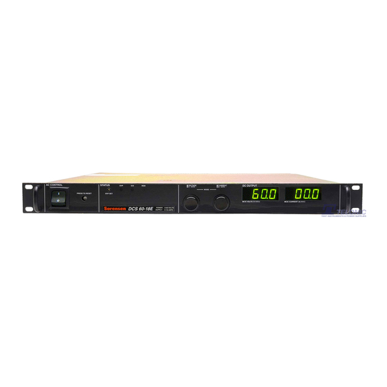
Page 26: Figure 2-1 Dcs Series Power Supply
Installation and Operation Sorensen DCS Series 1kW and 1.2kW Supplies Figure 2-1 DCS Series Power Supply M362500-01 Rev H... -
Page 27: Controls, Connectors, And Indicators
Sorensen DCS Series 1kW and 1.2kW Supplies Installation and Operation Controls, Connectors, and Indicators Refer to Figure 2-1 and the descriptions below. 2.4.1 Front Panel AC Power Switch AC Input Circuit Breaker OVP Adjust Potentiometer: Manual adjustment for OVP trip level... -
Page 28: J3 Program, Sense And Monitor Connector Description
Installation and Operation Sorensen DCS Series 1kW and 1.2kW Supplies 2.4.3 J3 Program, Sense and Monitor Connector Description D-subminiature 25-pin female; mating connector: 25-pin Male ITT Cannon DB25P or equivalent Pin # Function AC/DC Shutdown Input (12-250 Vac or 12-130 Vdc) -
Page 29: Initial Functional Tests
Sorensen DCS Series 1kW and 1.2kW Supplies Installation and Operation Initial Functional Tests Before connecting the unit to an AC outlet, make sure that the power switch is in the OFF position and that the voltage and current controls are turned fully counter clockwise. Check that the J3 mating connector on the rear of the unit is in place with jumpers connected for local operation as shown below. -
Page 30: Standard Operation
Installation and Operation Sorensen DCS Series 1kW and 1.2kW Supplies Standard Operation Reliable performance of the DCS power supply can be obtained if certain basic precautions are taken when connecting it for use on the lab bench or installing it in a system. -
Page 31: Inductive Loads
Sorensen DCS Series 1kW and 1.2kW Supplies Installation and Operation The preferred way to distribute power is by the radial distribution method in which power is connected to each load individually from a single pair of terminals designated as the positive and negative distribution terminals. -
Page 32: Remote Sensing
Installation and Operation Sorensen DCS Series 1kW and 1.2kW Supplies 2.6.4 Remote Sensing The use of remote sensing permits the regulation point of the power supply to be shifted from the output terminals to the load or other distribution terminals thereby automatically compensating for the voltage losses in the leads supplying the load (provided these losses do not exceed 1V/line [0.5V/line for the DCS 8-125 and DCS 10-100 models]). -
Page 33: Negative Output Operation
Sorensen DCS Series 1kW and 1.2kW Supplies Installation and Operation 2.6.5 Negative Output Operation Operation of the unit as a negative output supply may be accomplished by referencing the positive output terminal to the power supply chassis or some other common system ground. -
Page 34: Multiple Supplies
Installation and Operation Sorensen DCS Series 1kW and 1.2kW Supplies For voltage mode operation, turn the current control fully clockwise and then adjust the voltage control to obtain the desired output voltage. For current mode operation, turn the voltage control 1/2 turn clockwise, the current control fully counterclockwise and connect an appropriately sized shorting jumper across the output terminals. -
Page 35: Split Supply Operation
Sorensen DCS Series 1kW and 1.2kW Supplies Installation and Operation 2.8.3 Split Supply Operation Split supply operation is used to obtain two positive voltages with a common ground, or a positive-negative supply. To obtain two positive voltages, connect the negative terminals of both supplies together. -
Page 36: Remote Programming Of Ovp With External Voltage Sources
Installation and Operation Sorensen DCS Series 1kW and 1.2kW Supplies 2.9.2 Remote Programming of OVP With External Voltage Sources To remotely program the OVP trip level using a 0-5V or 0-10V DC voltage source, use the following procedure: 1. With the unit off and disconnected from its AC source, remove the cover and set switch SW1-4 closed (default factory setting) for 0-5V programming or open for 0- 10V programming. -
Page 37: Remote Programming Of Ovp With An External Resistance
Sorensen DCS Series 1kW and 1.2kW Supplies Installation and Operation SWITCH SW1 CONNECTOR J3 1312 OPEN CLOSED 0-10V Switch SW1 SW1-1 Off (Open) SW1-2 Off (Open) SW1-3 Off (Open) SW1-4 Off (Open) SW1-5 Off (Open) SW1-6 Off (Open) SW1-7 Off (Open) -
Page 38: Remote Programming Of Ovp With External Current Sources
Installation and Operation Sorensen DCS Series 1kW and 1.2kW Supplies SWITCH SW1 CONNECTOR J3 1312 OPEN CLOSED 5k OHMS Switch SW1 SW1-1 Off (Open) SW1-2 Off (Open) SW1-3 Off (Open) SW1-4 On (Closed) SW1-5 Off (Open) SW1-6 Off (Open) SW1-7 Off (Open) -
Page 39: Remote Ovp Sensing
Sorensen DCS Series 1kW and 1.2kW Supplies Installation and Operation SWITCH SW1 CONNECTOR J3 1312 OPEN CLOSED 0-1mA Switch SW1 SW1-1 Off (Open) SW1-2 Off (Open) SW1-3 Off (Open) SW1-4 On (Closed) SW1-5 Off (Open) SW1-6 Off (Open) SW1-7 Off (Open) -
Page 40: Remote On/Off By Contact Closure
Installation and Operation Sorensen DCS Series 1kW and 1.2kW Supplies level signal between pins 14 (positive) and 2 (return) of connector J3 determines the output conditions: TTL LOW = OUTPUT ON TTL HIGH = OUTPUT OFF For AC or DC operation, an input of 12-250 Vac (or 12-130 Vdc) between pins 1 (positive for DC input) and 2 (return) of connector J3 will disable the output of the supply. -
Page 41: Programming With External Voltage Sources
Sorensen DCS Series 1kW and 1.2kW Supplies Installation and Operation 2.11.1 Programming With External Voltage Sources The output voltage can be programmed using either a 0-5 Vdc or 0-10 Vdc external voltage source. To program the output voltage with a 0-5 Vdc source, set switch SW1-3 open (default factory setting) and remove the jumpers connecting pins 8 to 9 and 20 to 21 on connector J3. -
Page 42: Programming With An External Resistance
Installation and Operation Sorensen DCS Series 1kW and 1.2kW Supplies The output current limit can be programmed using a 0-5 Vdc or 0-10 Vdc external voltage source. Selection of the programming voltage is done using switches SW1-1 and SW1-2 as... - Page 43 Sorensen DCS Series 1kW and 1.2kW Supplies Installation and Operation SWITCH SW1 CONNECTOR J3 1312 OPEN CLOSED 5k OHMS Switch SW1 SW1-1 Off (Open) SW1-2 Off (Open) SW1-3 Off (Open) SW1-4 On (Closed) SW1-5 Off (Open) SW1-6 Off (Open) SW1-7 Off (Open)
-
Page 44: Programming With An External Current Source
Installation and Operation Sorensen DCS Series 1kW and 1.2kW Supplies 2.11.3 Programming With an External Current Source The output voltage and current limit can be programmed using an external 0-1mA current source. To program the output voltage, set the front panel voltage control to maximum, set switch SW1-3 open (default factory setting) and remove the jumper between pins 20 and 21 of connector J3. -
Page 45: 2.12 Remote Monitoring And Status Indicators
Sorensen DCS Series 1kW and 1.2kW Supplies Installation and Operation 2.12 Remote Monitoring and Status Indicators Readback signals for remote monitoring of the output voltage and current are available at connector J3 on the rear of the unit. A 0-5V (uncalibrated) signal between pins 19 (positive) and 12 (negative) represents 0-100% of the rated output voltage. -
Page 47: Section 3 Theory Of Operation
This section describes the operation of the A2 assembly switching regulator power circuit. Three subsections cover basic switching regulator theory, a simplified description of the Sorensen full bridge converter, and a more detailed circuit description intended for troubleshooting purposes. 3.1.1... -
Page 48: Figure 3-1 Simplified Full Bridge Converter
Theory of Operation Sorensen DCS Series 1kW and 1.2kW Supplies Figure 3-1 Simplified Full Bridge Converter M362500-01 Rev H... -
Page 49: Simplified Full Bridge Converter Theory
Sorensen DCS Series 1kW and 1.2kW Supplies Theory of Operation 3.1.2 Simplified Full Bridge Converter Theory See Figure 3-1. The input AC line voltage is rectified and filtered by CR35, C32(A,B,C), and C72(A,B,C) to a raw DC voltage which is supplied to the power FETs, Q13-Q16, on the primary of power transformer T1. - Page 50 Theory of Operation Sorensen DCS Series 1kW and 1.2kW Supplies NPUT ECTIFIER AND NRUSH IMITING Input AC power passes from the rear panel AC connector (TB1) through an RFI filter consisting of C1-6, R122, and common mode filter inductors L1, and L2 to the front panel power switch.
- Page 51 Sorensen DCS Series 1kW and 1.2kW Supplies Theory of Operation UTPUT ECTIFIER IRCUIT AND UTPUT ILTER The DCS series uses two different configurations for the output rectifier. The 8V to 100V models use a full wave center tap configuration while the 150 to 600V models employ a full wave bridge.
- Page 52 Theory of Operation Sorensen DCS Series 1kW and 1.2kW Supplies OLTAGE ONTROL IRCUIT The output voltage feedback is monitored by the voltage control op amp U5 pin 3 via the positive sense line (pin 13 of connector J3 on 8V to 100V models and on pin 1 of the Amp high voltage connector) and the resistor divider formed by R21, R22, R53, R85 and R147.
- Page 53 Sorensen DCS Series 1kW and 1.2kW Supplies Theory of Operation PERATING NDICATOR IRCUIT Op amp U8-2 monitors the polarity of the voltage across diode CR18. CR18 is forward biased during voltage mode and reverse biased during current mode to provide a mode indication signal at U8 pin 7.
- Page 54 Theory of Operation Sorensen DCS Series 1kW and 1.2kW Supplies During remote voltage programming of the OVP trip level the internal 1mA current source is disconnected by removing the jumper that connects pin 3 and 16 of J3. The reference voltage at pin 6 of U3-2 is then provided directly by the external voltage source.
-
Page 55: Meter Circuit (A1 Assembly)
Sorensen DCS Series 1kW and 1.2kW Supplies Theory of Operation The front panel remote programming indicator is controlled by op amp U8-4. Resistors R55 and R56 form a voltage divider with the 6.2V reference which develops a nominal 0.3V at pin 12 (the non-inverting input) of the op amp. -
Page 56: Voltmeter
Theory of Operation Sorensen DCS Series 1kW and 1.2kW Supplies 3.2.1 Voltmeter U2 is a 3 1/2 digit analog to digital converter which converts the analog input from the A2 board voltage control circuit to a digital display on seven segment displays DS5-DS8 (maximum display is 1999). -
Page 57: Section 4 Maintenance, Troubleshooting, And Calibration
SECTION 4 MAINTENANCE, TROUBLESHOOTING, AND CALIBRATION General This section provides periodic maintenance, calibration and troubleshooting information. Periodic Service Routine service consists only of annual calibration and periodic cleaning. Whenever a unit is removed from service, it should be cleaned, using denatured or isopropyl alcohol or an equivalent solvent on the metal surfaces and a weak solution of soap and water for the front panel. -
Page 58: Preliminary Checks
Maintenance and Troubleshooting Sorensen DCS Series 1kW and 1.2kW Supplies 4.3.1 Preliminary Checks If the power supply displays any unusual or erratic operation shut the power supply off immediately and disconnect it from the AC power source. Check all load, programming and monitoring connections and circuits. -
Page 59: Calibration
Sorensen DCS Series 1kW and 1.2kW Supplies Maintenance and Troubleshooting Symptom Check Further Checks and Corrections Output voltage Is unit at current limit? See Section 2.5. fluctuating or Is input voltage within Measure voltage on input terminals. regulation poor specified range? See Section 1.4. - Page 60 Maintenance and Troubleshooting Sorensen DCS Series 1kW and 1.2kW Supplies ure 4-1 Trimpot Locations Refer to the Safety Notice at the beginning of this manual for an explanation of these symbols. M362500-01 Rev H...
-
Page 61: Section 5 Parts Lists
Most assemblies consist of parts common to all series models as well as parts that are model-specific, or differential. Parts Ordering Do not substitute parts without first checking with Customer Service Department. Sorensen parts may be ordered from the factory with the information in the following sections. Order parts from:... -
Page 62: Parts Lists
Parts Lists Sorensen DCS Series 1kW and 1.2kW Supplies Parts Lists Table 5–1 provides fuse ratings for the DCS 1kW and DCS 1.2kW power supplies. Table 5–2 provides a matrix of parts lists according to model numbers for the DCS 1kW power supplies, and Table 5–3 provides a listing of the parts lists. -
Page 63: Table 5-3 Dcs 1Kw Parts Lists
Sorensen DCS Series 1kW and 1.2kW Supplies Parts Lists Number Assembly 1066830-008 Output PCB Assembly 1066830-01 Output PCB Assembly 1066830-020 Output PCB Assembly 1066830-080 Output PCB Assembly 1066830-100 Output PCB Assembly 5360726-01 Rectifier PCB Assembly 5360726-02 Rectifier PCB Assembly 5360726-03... -
Page 64: Table 5-4 Dcs 1.2Kw Parts Lists By Model Number
Parts Lists Sorensen DCS Series 1kW and 1.2kW Supplies Front Panel Rectifier Final Mother PCB Output PCB Model Assembly Assembly Assembly Assembly Assembly DCS8-140E 5362500-008 5362462-008 5360801-01 1066830-008 DCS10-120E 5362500-010 5362462-010 5360801-01 1066830-008 DCS20-60E 5362500-020 5362462-020 5360801-02 1066830-020 DCS33-36E 5362500-033... -
Page 65: Table 5-5 Dcs 1.2Kw Parts Lists
Sorensen DCS Series 1kW and 1.2kW Supplies Parts Lists Number Assembly 1066830-008 Output PCB Assembly 1066830-01 Output PCB Assembly 1066830-020 Output PCB Assembly 1066830-080 Output PCB Assembly 1066830-100 Output PCB Assembly 5360726-01 Rectifier PCB Assembly 5360726-02 Rectifier PCB Assembly 5360726-03...
Need help?
Do you have a question about the DCS8-125E and is the answer not in the manual?
Questions and answers