
Related Manuals for Sorensen XBT32-3FTP


Summary of Contents for Sorensen XBT32-3FTP
- Page 1 XBT32-3FTP Benchtop DC Power Supply Operation Manual M370187-01 Rev J www.programmablepower.com...
-
Page 5: About Ametek
About AMETEK AMETEK Programmable Power, a Division of AMETEK, Inc., is a global leader in the design and manufacture of precision, programmable power supplies for R&D, test and measurement, process control, power bus simulation and power conditioning applications across diverse industrial segments. - Page 6 This page intentionally left blank.
-
Page 7: Important Safety Instructions
Neither AMETEK Programmable Power Inc., San Diego, California, USA, nor any of the subsidiary sales organizations can accept any responsibility for personnel, material or inconsequential injury, loss or damage that results from improper use of the equipment and accessories. - Page 8 This page intentionally left blank.
- Page 9 AMETEK will, at its expense, deliver the repaired or replaced Product or parts to the Buyer. Any warranty of AMETEK will not apply if the Buyer is in default under the Purchase Order Agreement or where the Product or any part thereof: is damaged by misuse, accident, negligence or failure to maintain the same as •...
- Page 10 This page intentionally left blank...
-
Page 11: Table Of Contents
2.6 Warming Up .................... 2-2 2.7 Maintenance or Repair ................2-3 OPERATION ................3-1 3.1 XBT32-3FTP Front Panel ............... 3-1 3.2 XBT32-3FTP Rear Panel ............... 3-11 OPERATION SETTING .............. 4-1 4.1 Voltage Setting ..................4-1 4.2 ... - Page 12 & numerical key “2” simultaneously..........6-2 6.1.3 How to enter calibration mode of CH3 : Press the rotary & numerical key “3” simultaneously..........6-4 Figures Figure 3-1. XBT32-3FTP Front Panel ..............3-1 Figure 3-2. XBT32-3FTP Rear Panel ..............3-11 viii M370187-01 Rev J...
-
Page 13: Introduction
The XBT32-3FTP is a programmable benchtop power supply that provides variable DC low voltage power to devices and assemblies in a laboratory setting. This section provides an overview of the XBT32-3FTP DC Power Supply and lists its features, functions and specifications. -
Page 14: Minimum System Requirements For Ethernet Option
Introduction memory to store 100 configurations for recall • built-in timer (1sec – 100 hrs) to disable power • over voltage protection (OVP) • over current protection (OCP) • key lock • load and line regulation within .01% • remote control mode with less than 50 ms transient time •... -
Page 15: Specifications
Introduction 1.3 Specifications Model XBT32-3FTP Channel NO. CH1 & CH2 Output Voltage 0 - 32V 0 - 15V Output Current 0 - 3A 0 - 5A Output Power (CH3 Auto Ranging) Line Regulation ±(% of output +offset) Voltage 0.01% + 2mV Current 0.01% + 300uA... - Page 16 Introduction Tracking Accuracy ±(% of output +offset) Voltage 0.02% + 10mV Transient Response Time For 50% load change (25 to 50µS 75% to within 20mV Stability,constant output & temperature ±(% of output +offset), 8hrs 0.02% + 2mV Voltage 0.01% + 1mA Current Voltage Programming Speed Rising Time at Full Load...
-
Page 17: Installation And Maintenance
INSTALLATION AND MAINTENANCE This section describes installation and maintenance requirements. 2.1 Initial Inspection Remove device from packaging; inspect for any physical damage incurred during shipment; report any such damage to the carrier. 2.2 Conditions of Use Operate indoors only. • Refer to Section 1.3, Specifications, of this manual. -
Page 18: Power-Line Voltage
Installation and Maintenance 2.3 Power-Line Voltage The power supply uses AC power 115V/230V 50Hz/60Hz. Before plugging in the power cord, make sure the POWER switch (see Section 3.1) is in the OFF position and the voltage input selection switch on the bottom of the unit is the same as the required voltage. -
Page 19: Maintenance Or Repair
Installation and Maintenance accuracy in the specification, 30 minutes or longer is necessary. 2.7 Maintenance or Repair When the power supply is not in use or is unattended, make sure to turn off the power switch. When necessary, remove dust with a damp cloth. If the power supply needs repair, follow the Warranty instructions (page v) in this manual. - Page 20 Installation and Maintenance This page intentionally left blank. M370187-01 Rev J...
-
Page 21: Operation
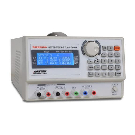
OPERATION This section describes the features, controls and functions of the XBT front and rear panels. 3.1 XBT32-3FTP Front Panel Figure 3-1. XBT32-3FTP Front Panel M370187-01 Rev J... -
Page 22: Adjust Voltage 4
Operation (1) Display: 20x4 blue backlight LCD (2) Rotary Adjust/Enter Control: This control has two functions: Rotate to adjust voltage and current. • Press to enter any input. • (3) M: Memory key to either store a new configuration or recall a previously stored configuration. - Page 23 2BOperation (9) DISP: Display key to select either the voltage/current or power/resistance readout to show in the display screen. (10) V(Voltage): Sets voltage after value is input by either the Adjust control (2) or the number keys (6). (11) A(Current): Sets current after value is input by either the Adjust control (2) or the number keys (6).
- Page 24 Operation rotary + CLEAR again. 2. TRACKING: The initial value is OFF, switch to ON by pressing the rotary. The CH2 will have the same voltage and current setting as the CH1. 3. OVP setting: Over voltage protection. Press the rotary to enter OVP Configuration.
- Page 25 2BOperation number keys to input the OCP value; press rotary (Enter) to “set” (save) the value just input. Press ON/OFF to enable or disable OCP. 5. Baud rate: Transmission speed. Select baud rate for 1200, 2400, 4800, 9600, 19200, 38400 by using rotary. M370187-01 Rev J...
- Page 26 Operation 6. Interface: Transmission interface. Select RS232, USB, GPIB (XBT32-3FTP optional), LAN Port (XBT32-3FTP optional) by using rotary. • RS-232 Setup Parameters: Parity none Data Bits I Stop Bits 1 • DB9 Connector Definition Pin 2 TX Pin 3 RX Pin 5 Ground 7.
- Page 27 2BOperation 8. IP 170.85.170: This parameter is for LAN port setting. (Default LAN configuration is: static, IP address 0.0.0.0, subnet mask 255.255.255.0). Set a static IP address with DHCP “Off.” Use the ◄►keypads to position the cursor at each value in the IP address;...
- Page 28 Operation enable parallel output. The total output current is equal to the output of both CH1 and CH2 when they are parallel-connected. 12. Serial out: Serial output. The initial value is OFF. Press rotary to enable serial output. The total output voltage is 4equal to the total voltage of CH1 and CH2 when they are serial-connected.
- Page 29 2BOperation corresponding memory locations. 15. Initial Mode: Save most recent settings to memory before powering off, to be recalled at next power on. The initial value is OFF. Press rotary to enable the function (ON) prior to powering off. 16. Out Mode: Output mode. The initial value is single. Press rotary to switch to multi mode.
- Page 30 Operation 17. Factory Preset: Reset to default settings 18. Back Main Menu: End configuration mode and save the settings. (13) (LCL): Either decimal point or, when in REMOTE mode, resets to LOCAL mode. (14) CLEAR (ESC): Clear the number input. Or, return to the previous display. (15) Power Switch (POWER ON/OFF): raised position █...
-
Page 31: Xbt32-3Ftp Rear Panel
2BOperation 3.2 XBT32-3FTP Rear Panel Figure 3-2. XBT32-3FTP Rear Panel (18) AC Power Input: Connector for AC source (115V/230V). (19) Fuse compartment: The fuse used for power source. When the switch set to 115V, using 5A slow fuse; set to 230V, using 2.5A slow fuse. - Page 32 Operation (21) CH1 ±S / CH2 ± S: Connect the +Sense to the positive pole of the device under test (DUT) and the –Sense to the negative pole of the DUT. When the DIP switches are set to Remote sense, the power supply has voltage compensation, and measures and controls voltage at the DUT.
-
Page 33: Operation Setting
OPERATION SETTING 4.1 Voltage Setting Press “CH” to select channel (CH1, CH2 or CH3), indicated by the location of the asterisk (*) in the LCD. Use the number keys to input the voltage; press “V” to accept the voltage value. 4.2 Current Setting Press “CH”... -
Page 34: Set Ovp
Operation Setting 4.3 Set OVP Press “Config” to enter Configuration mode; turn rotary or press the ◄► keys to move the cursor to OVP setting. Press rotary to enter OVP setting display. Press “CH” to select channel to be set (CH1, CH2 or CH3), indicated by the location of the asterisk (*). -
Page 35: Remote Interface Protocol And Package Mode
REMOTE INTERFACE PROTOCOL AND PACKAGE MODE This section presents communication protocol, which includes SCPI instructions and low-error protocol. 5.1 Introduction SCPI compliant commands allow remote operation, control and monitoring of the power supply by connecting to a personal computer (PC) via USB, IEEE-488.2 or RS-232 interface. -
Page 36: Error Message List
Note: All commands must end with the <NL> and <Rtn>. And there must be a space between the command and the parameter. For example, to set the GPIB address of 10 to a XBT32-3FTP . The command line is as follows: ADDR 10<NL><Rtn>... -
Page 37: Scpi Compatible Information
Remote Interface Protocol and Package Mode -059 Cannot create timer -060 Password error -088 Media protected -089 Expression Error -100 Program error -101 Cannot create program -104 Program currently running -105 Program syntax error -106 Program runtime error -108 Syntax error -109 Data type error -110... -
Page 38: Scpi Command For Subsystem
Remote Interface Protocol and Package Mode complete before executing commands following the *WAI command. Examples: How to save V/I to memory: *SAV 15 ==> Saves current settings to memory number 15 SAV 0 ==> Saves current settings to memory number 0 How to recall memory V/I variable to output: *RCL 3 ==>... - Page 39 Remote Interface Protocol and Package Mode :ERRor[?] read back machine error code :CCP[?] read back Iset DAC value :CVP[?] read back Vset DAC value :MONV[?] read back Vout DAC value :MONI[?] read back Iout DAC value PROGram program subsystem [ state/bool] ON/1 (enable) or OFF/0 (disable) program action [ n]...
- Page 40 Remote Interface Protocol and Package Mode MEMory memory subsystem [ n] select [n] page memory number, n range from 0 ~ 99 :VSET[n] volt setting for channel n: 1 - 3 [ level] voltage level: 0 – 32V for ch1 and ch2, 0 – 15V for ch3 :ISET[n] current setting for channel n...
- Page 41 Remote Interface Protocol and Package Mode [ n] channel number n: 1 - 3 :ADDRess set up GPIB address for XBT32-3FTP [?/ n] return or set GPIB address n: 1 - 31 :DEFault resume factory preset (password protected) :PWD enter password to verify...
- Page 42 Remote Interface Protocol and Package Mode [ state/bool] ON/1 (enable) or OFF/0 (disable) OCP :VOLTage[n] Sets the floating point value of the DC output voltage in volts for channel n: 1 - 3. [ level] voltage level: 0 – 32V for ch1 and ch2, 0 – 15V for ch3 :PROTection over voltage protection (OVP)
- Page 43 Remote Interface Protocol and Package Mode STAT:ERROR? How to read voltage setting DAC value: STATUS:CVP? ==> read CVP DAC value How to read current setting DAC value: STATUS:CCP? ==> read CCP DAC value How to read voltage DAC value: STATUS:MONV? ==>...
- Page 44 Remote Interface Protocol and Package Mode How to set up a program (example): step 1: PROG 10 ==> select program number 10, program number shall be in 0 ~ 99. step 2: PROG:VSET1 16V ==> set output voltage to 16v for ch1 step 3: PROG:VSET2 25V ==>...
- Page 45 Remote Interface Protocol and Package Mode How to read memory parameter: step 1: MEM 2 ==> select memory number is 2 step 2: MEM? ==> read back memory NO.2 parameter How to set up GPIO direction: GPIO Pin 9 Pin 8 Pin 7 Pin 6 Pin 5...
- Page 46 Remote Interface Protocol and Package Mode How to read back serial number: MEM:SERIAL? MEMORY:SER? How to modify machine ID (address): CONTROL:ADDR 23 ==> modify id to 23 CONT:ADDRESS 09 ==> modify id to 9 How to check password: CONT:PASSWORD 123456 ==>...
- Page 47 Remote Interface Protocol and Package Mode IOUT1? ==> read back current 1 result IOUT2? ==> read back current 2 result How to measure voltage: MEASURE:VOLT1? ==> read back voltage 1 result MEAS:VOLTAGE3? ==> read back voltage 3 result MEAS:VOLT3? ==> read back voltage 3 result VOUT1? ==>...
- Page 48 Remote Interface Protocol and Package Mode SOUR:VOLTAGE3:PROT 12 ==> set over voltage to 12V for channel 3. SOURCE:VOLT1:PROT 30 ==> set over voltage to 30V for channel 1. SOUR:VOLT2:PROTECTION 10 ==> set over voltage to 10V for channel 2. VOLTAGE3:PROT 7 ==>...
- Page 49 Remote Interface Protocol and Package Mode CURR1:PROTECTION? ==> return over current for channel 1 CURR:PROTECTION? ==> return over current for channel 1 OISET2? ==> return over current for channel 2 How to enable or disable over voltage protection (OVP): SOUR:VOLTAGE3:PROT:TRIG ON ==>...
- Page 50 Remote Interface Protocol and Package Mode PROG:NEXT:NEXT ==> go on to program 11 PROG? ==> read back the setting of program 10 for verification PROG 11 ==> define program 11 PROG:ISET1 1 ==> ch1 output up to 1 A PROG:ISET2 1 ==>...
-
Page 51: Rules Of Status Definition
==> return the IP address CONTROL:IP? ==> return the IP address How to set the IP address: CONT:IP 192.168.10.1 ==> set up the IP address for XBT32-3FTP CONTROL:IP 192.168.10.1 ==> set up the IP address 5.5 Rules of Status Definition byte 0:... - Page 52 Remote Interface Protocol and Package Mode byte 2: bit 7 disable remote mode, inhib communication bit 6 programmable flag bit 5 remote flag bit 4 keypad between push and pop status bit 3 machine running at time mode bit 2 machine running at sub-menu mode bit 1 machine running at configuration sub-menu mode...
- Page 53 Remote Interface Protocol and Package Mode bit 5 reserved bit 4 reserved bit 3 DHCP on or off flag bit 2 when the bit is on,LCD to display minus ('-') signal bit 1 fast-output flag bit 0 RESERVED byte 7: fan PWM value.
-
Page 55: Calibration Procedure
First, you can read the screen of the voltage calibration mode of CH1, XBT32-3FTP shall output one low voltage. Please read the actual reading from your electric meter and input the value to XBT32-3FTP. Then press the rotary to confirm the data input. Second, XBT32-3FTP shall output one high voltage. -
Page 56: How To Enter Calibration Mode Of Ch2 : Press The Rotary & Numerical Key "2" Simultaneously
First, you can read the screen of the current calibration mode of CH1, XBT32-3FTP shall output one low current. Please read the actual reading from your electric meter and input the value to XBT32-3FTP. Then press the rotary to confirm the data input. Second, XBT32-3FTP shall output one high current. - Page 57 First, you can read the screen of the voltage calibration mode of CH2, XBT32-3FTP shall output one low voltage. Please read the actual reading from your electric meter and input the value to XBT32-3FTP. Then press the rotary to confirm the data input. Second, XBT32-3FTP shall output one high voltage.
-
Page 58: How To Enter Calibration Mode Of Ch3 : Press The Rotary & Numerical Key "3" Simultaneously
First, you can read the screen of the current calibration mode of CH2, XBT32-3FTP shall output one low current. Please read the actual reading from your electric meter and input the value to XBT32-3FTP. Then press the rotary to confirm the data input. Second, XBT32-3FTP shall output one high current. - Page 59 First, you can read the screen of the voltage calibration mode of CH3, XBT32-3FTP shall output one low voltage. Please read the actual reading from your electric meter and input the value to XBT32-3FTP. Then press the rotary to confirm the data input. Second, XBT32-3FTP shall output one high voltage.
- Page 60 First, you can read the screen of the current calibration mode of CH3, XBT32-3FTP shall output one low current. Please read the actual reading from your electric meter and input the value to XBT32-3FTP. Then press the rotary to confirm the data input. Second, XBT32-3FTP shall output one high current.
Need help?
Do you have a question about the XBT32-3FTP and is the answer not in the manual?
Questions and answers