
Subscribe to Our Youtube Channel
Related Manuals for Sorensen XT Series


Summary of Contents for Sorensen XT Series
- Page 1 INSTRUCTION MANUAL Instruction Manual for XT SERIES Power Supply This manual covers models: 60-1 15-4 120-0.5 20-3 250-0.25 30-2 TM-6000-SN...
- Page 2 SORENSEN WARRANTY This unit is guaranteed for five (5) years from the date of delivery against defects in material and workmanship. This does not apply to products damaged through accident, abuse, misuse, or unauthorized repair. The manufacturer shall not be liable for any special or consequential damage of any nature. The manufacturer will repair or replace the non-conforming product or issue credit, at its option, provided the manufacturer's inspection establishes the existence of a defect.
-
Page 3: About This Manual
ABOUT THIS MANUAL About This Manual This manual contains user information for the XT Series DC power supply. It provides information about features and specifications, installation procedures, and basic functions testing, as well as operating procedures for using both standard and multiple supply functions. It also includes a complete set of schematics, circuit descriptions, and parts lists for the assemblies used in the supply. -
Page 4: Manual Changes
MANUAL CHANGES INSTRUCTION MANUAL Manual Changes Nothing at this time. Release 4.2 (2001/06) -
Page 5: Table Of Contents
INSTRUCTION MANUAL CONTENTS CONTENTS About This Manual............................i Manual Changes ............................ii Contents............................... iii List of Figures ............................. v List of Tables............................... v 1. FEATURES AND SPECIFICATIONS 1.1 Description............................. 1-1 1.2 Features............................1-1 1.3 Options and Accessories........................ 1-2 1.4 Specifications..........................1-2 1.4.1 Electrical Specifications ...................... -
Page 6: Contents
CONTENTS INSTRUCTION MANUAL 5. MAINTENANCE 5.1 Introduction............................5-1 5.2 Units Under Warranty........................5-1 5.3 Periodic Servicing..........................5-1 5.4 Test Equipment ..........................5-1 5.5 Troubleshooting..........................5-2 5.5.1 Blown Fuses ........................5-2 5.6 Calibration .............................5-2 5.6.1 Front Panel Assembly (A1) Calibration ................5-2 5.6.2 Power Assembly (A2) Calibration..................5-3 5.7 Replacement Parts..........................5-3 5.7.1 Parts Replacement and Modifications .................5-3 5.7.2 Ordering Parts........................5-3 5.7.3 Front Panel Assembly (A1) Replacement Parts..............5-4... - Page 7 INSTRUCTION MANUAL ILLUSTRATIONS AND TABLES LIST OF ILLUSTRATIONS Figure 2.1-1 XT Series Supply Front Panel ....................2-1 Figure 2.1-2 XT Series Supply Rear Panel ....................2-1 Figure 3.5-1 Operating Modes ........................3-3 LIST OF TABLES Table 1.1-1 XT Series Models ........................1-1 Table 1.4-1 Electrical Specifications......................
-
Page 8: Features And Specifications
FEATURES AND SPECIFICATIONS Description The XT Series of linear, regulated DC power supplies provides reliable, high performance solutions for a wide variety of laboratory, development, and system applications. The series consists of six basic models that may be purchased as single units or combined as dual, triple, or quadruple configurations containing any combination of models. -
Page 9: Options And Accessories
FEATURES AND SPECIFICATIONS INSTRUCTION MANUAL Options and Accessories • Internal Analog Programming (APG) Interface for analog signal control of voltage and current, overvoltage protection (OVP), master/slave output tracking, and remote ON/OFF. • Internal RS232 Interface for serial instrument programming using RS232 protocol. •... -
Page 10: Table 1.4-2 Additional Characteristics
INSTRUCTION MANUAL FEATURES AND SPECIFICATIONS 1.4.1 Electrical Specifications (continued) AC Input Voltages Standard: 115Vac ±10%, 57-63Hz Option M1 (Factory-installed): 110Vac ±10%, 47-63Hz Option AC220 220Vac ±10%, 47-63Hz Option AC230 230Vac ±10%, 47-63Hz Option AC240 240Vac ±10%, 47-63Hz AC Input Current Single Unit: 1.2A Dual Unit:... -
Page 11: Mechanical Specifications
FEATURES AND SPECIFICATIONS INSTRUCTION MANUAL 1.4.2 Mechanical Specifications Unit Height Width Depth Weight Single 132mm (5.25in) 109mm (4.25in) 297mm (11.7in) 4.3kg (9.5lb) Dual 132mm (5.25in) 216mm (8.5in) 297mm (11.7in) 8.1kg (17.9lb) Triple 132mm (5.25in) 325mm (12.75in) 297mm (11.7in) 12.0kg (26.3lb) Quad 132mm (5.25in) 436mm (17.0in) -
Page 12: Installation
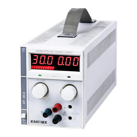
Refer to the front and rear panel drawings in Figures 2.1-1 and 2.1-2 as needed. Figure 2.1-1 XT Series Supply Front Panel Figure 2.1-2 XT Series Supply Rear Panel... -
Page 13: Initial Inspection
INSTALLATION INSTRUCTION MANUAL Initial Inspection CAUTION Follow established antistatic procedures. There are static-sensitive parts on the printed circuit boards. The power supply comes complete with an IEC power cord set and a technical manual. Inspect the equipment for damage as follows: 1. -
Page 14: Output Biasing
INSTRUCTION MANUAL INSTALLATION Output Biasing WARNING Use extreme caution when biasing the output relative to the chassis due to potential high voltage levels at the output terminals. To bias the output voltage relative to ground, we recommend that you use a 0.01µF capacitor of sufficient voltage rating (200 to 1000V) in place of the shorting connection. -
Page 15: Load Connection And Operation
INSTRUCTION MANUAL LOAD CONNECTION AND OPERATION LOAD CONNECTION AND OPERATION Introduction This section covers: • Single and multiple load connection • Constant Voltage and Constant Current operating modes • Alternate power supply configurations such as series and parallel connections Load Connection To obtain a stable, low noise output, pay careful attention to conductor ratings, system grounding techniques AC input, DC output, and remote sensing connections. -
Page 16: Remote Sensing
LOAD CONNECTION AND OPERATION INSTRUCTION MANUAL Remote Sensing Remote sensing shifts the regulation point of the power supply from the output terminals to the load or other distribution terminals. It compensates for voltage losses of up to a total of 0.5 volts in the power leads supplying the load. -
Page 17: Standard Operation
INSTRUCTION MANUAL LOAD CONNECTION AND OPERATION Standard Operation Your power supply has two basic operating modes: Constant Voltage Mode and Constant Current Mode. The operating mode depends on the combination of: • Output voltage setting • Output current limit setting •... -
Page 18: Constant Voltage Mode Operation
LOAD CONNECTION AND OPERATION INSTRUCTION MANUAL 3.5.1 Constant Voltage Mode Operation The power supply will operate in constant voltage mode whenever the load current I is less the current limit setting I , or: I < I (Note: I ). In constant voltage mode, the power supply maintains the output voltage at the selected value (V ) while the load current I varies with the load requirements. -
Page 19: Series, Parallel, And Split Supply Operation
INSTRUCTION MANUAL LOAD CONNECTION AND OPERATION Series, Parallel, and Split Supply Operation You can operate two or more power supplies with outputs in series or in parallel to obtain increased load voltage or current. A split supply configuration allows you to obtain two positive outputs or a positive and a negative output. -
Page 20: Theory Of Operation
INSTRUCTION MANUAL THEORY OF OPERATION THEORY OF OPERATION Introduction This section describes the internal operation of your power supply. It starts with a description of the A2 Assembly power circuit and goes on to cover the A1 Assembly front panel. Use this information when configuring new applications or troubleshooting. - Page 21 THEORY OF OPERATION INSTRUCTION MANUAL As the power is turned on, C8 delays turn on of analog gate U1B, which in turn gates U1A on for a short period following power-on. This clamps the input to U3A pin 3 to the negative voltage set by CR3 and R13. A negative voltage at U3A pin 3 causes U3A to go negative and turn off Q4 via CR6, turning off the output.
- Page 22 INSTRUCTION MANUAL THEORY OF OPERATION Output Circuit Connector lines J1-1 through J1-4 connect the output power to the front panel binding posts. The positive and negative sense points for the voltage control circuit are located at J2-8 and J2-9 respectively. It is at these sense points that U3A maintains voltage regulation, so that remote sensing is possible by connecting the positive and negative sense lines to the desired regulation points.
-
Page 23: Meter Circuit (A1 Assembly)
THEORY OF OPERATION INSTRUCTION MANUAL Meter Circuit (A1 Assembly) Refer to the schematic in Appendix A for the following discussion. You will find the meter circuit on the A1 assembly circuit board. Voltage Display The analog input signal from the A2 power board is divided down so that 1mV between P102-7 and P102-5 represents 1 volt at the output of the power supply. -
Page 24: Maintenance
INSTRUCTION MANUAL MAINTENANCE MAINTENANCE WARNING Always disconnect power discharge circuits before replacing components. When servicing the supply, ensure another person with first aid and resuscitation certification is present. Ensure only experienced technical personnel make any repairs. Use proper static control techniques to avoid damage to front panel display drivers and other static-sensitive parts. -
Page 25: Troubleshooting
MAINTENANCE INSTRUCTION MANUAL Troubleshooting WARNING Potentially lethal voltages exist in the power circuit (on the A2 Assembly PCB). Troubleshoot with care after familiarizing yourself with circuit operation and use appropriate high voltage testing techniques. Assign service and repair to experienced technical personnel only. Remember that filter capacitors can store potentially dangerous energy for some time after you turn off the power. -
Page 26: Power Assembly (A2) Calibration
INSTRUCTION MANUAL MAINTENANCE 5.6.2 Power Assembly (A2) Calibration Table 5.6-2 Calibration (A2) A2 Calibration Resistor Parameter Affected Maximum output current. Set for 5% above rated output current. Current display accuracy Pass element crossover. Factory set. +10 volt reference level. Set for most accurate voltage display. Replacement Parts This section provides schematic drawings and parts lists for the following assemblies: •... -
Page 27: Front Panel Assembly (A1) Replacement Parts
MAINTENANCE INSTRUCTION MANUAL 5.7.3 Front Panel Assembly (A1) Replacement Parts Table 5.7-1 A1 Front Panel Assembly Common Parts Designation Description Part Number Complete Assembly A1 PCB Assembly (Specify model.) X2-6xxx-A1 C101,102 CL-100C-50 10µF 50V 2.mm Electrolytic Radial Capacitor 5x11 C103,105,107,108, CC-104D-09 0.1µF 50V Z5U +80% to -20% 2.5mm Ceramic Radial Capacitor 109,112,118,119... -
Page 28: Table 5.7-2 A1 Front Panel Assembly Differential Parts
INSTRUCTION MANUAL MAINTENANCE 5.7.3 Front Panel Assembly (A1) Replacement Parts Table 5.7-2 A1 Front Panel Assembly Differential Parts Designation Description Part Number 7 Volts C117 CD-104J-26 0.1µF 250V MF 10% 10mm Radial Capacitor Q101 MPS-A92 PB 300V 500mA 625mW QN-MPSA-92 R101,102A R-3650-41 365Ω... - Page 29 MAINTENANCE INSTRUCTION MANUAL 5.7.3 Front Panel Assembly (A1) Replacement Parts Table 5.7-2 A1 Front Panel Assembly Differential Parts (continued) Designation Description Part Number 60 Volts C117 CD-104J-26 0.1µF 250V MF 10% 10mm Radial Capacitor Q101 MPS-A92 PB 300V 500mA 625mW QN-MPSA-92 R101,102 R-3650-41...
-
Page 30: Power Assembly (A2) Replacement Parts
INSTRUCTION MANUAL MAINTENANCE 5.7.4 Power Assembly (A2) Replacement Parts Table 5.7-3 A2 Power Assembly Common Parts Designation Description Part Number Complete Assembly A2 PCB Assembly (Specify model.) X2-6xxx-A2 1nF 100V X7R 10% 5mm Ceramic Radial Capacitor CB-102F-16 CJ-100D-25 10µF 25V Tantalum 20% 2.5mm C4,15,17,27 CL-100C-50 10µF 50V 2mm Electrolytic Radial Capacitor... -
Page 31: Table 5.7-4 A2 Power Assembly Differential Parts
MAINTENANCE INSTRUCTION MANUAL 5.7.4 Power Assembly (A2) Replacement Parts TABLE 5.7-3 A2 Power Assembly Common Parts (continued) Designation Description Part Number R37A 2k ¼W 1% MF R-2001-41 R37B Resistor Empty Position R-EMPT R40,51 R-3920-41 392Ω ¼W 1% R-1300 130Ω ¼W 5% CF R42,46 R-5110-41 511Ω... - Page 32 INSTRUCTION MANUAL MAINTENANCE 5.7.4 Power Assembly (A2) Replacement Parts Table 5.7-4 A2 Power Assembly Differential Parts 15 Volts CL-101F-63 100µF 63V 10x20, 5mm 20% El Rad Capacitor 22pF 100V X7R 10% 5mm Radial Capacitor CB-220F-16 100pF 100V Z5 10% 5.00mm Cer Rad CB-101F-16 C,11,13 47pF 100V X7R 10% 5mm Radial Capacitor...
- Page 33 MAINTENANCE INSTRUCTION MANUAL 5.7.4 Power Assembly (A2) Replacement Parts TABLE 5.7-4 A2 Power Assembly Differential Parts (continued) Designation Description Part Number 30 Volts CL-330F-76 33µF 100V 5mm 20% El Rad Capacitor 22pF 100V X7R 10% 5mm Radial Capacitor CB-220F-16 47pF 100V X7R 10% 5mm Radial Capacitor CB-470F-16 C11,12 100pF 100V X7R 10% 5mm Radial Capacitor...
- Page 34 INSTRUCTION MANUAL MAINTENANCE 5.7.4 Power Assembly (A2) Replacement Parts TABLE 5.7-4 A2 Power Assembly Differential Parts (continued) Designation Description Part Number 120 Volts C1 Output Cap CL-3U3F-78 3.3µF 160V 5mm El Rad Capacitor C2A,19,22 Capacitor Empty Location C-EMPT C3A, 11 100pF 100V X7R 10% 5mm Radial Capacitor CB-101F-16 220pF 100V X7R 10% 5mm Radial Capacitor...
-
Page 35: Chassis Assembly Replacement Parts
MAINTENANCE INSTRUCTION MANUAL 5.7.5 Chassis Assembly Replacement Parts Table 5.7-5 Chassis Assembly Designation Description Part Number AC Wiring 2.5A Slow 250V 3AG fuse F2-0250-S For AC I/P Connector #4-40 x " Philips Pan Screw Stainless Steel MS-4P28-05MS Barrier Strip Fast-On Female ¼” x .032” AWG 18-22 MC-0251-F0 Wire Assembly 9 PIN Female MTA 0.1”... - Page 36 INSTRUCTION MANUAL APPENDIX A APPENDIX A ASSEMBLY SCHEMATIC A1 Assembly (Front Panel) and A2 Assembly (Power Circuit) Release 4.2 (2001/06)
- Page 37 Sorensen Company Toll Free (USA) 1-800-525-2024 9250 Brown Deer Road Sales Support: (858) 450-0085 E-Mail: sales@sorensen.com San Diego, CA USA 92121 FAX: (858) 458-0267 Website: www.sorensen.com...
Need help?
Do you have a question about the XT Series and is the answer not in the manual?
Questions and answers