
Subscribe to Our Youtube Channel
Related Manuals for Sorensen DLM 5–75


Summary of Contents for Sorensen DLM 5–75
-
Page 1: Power Supplies
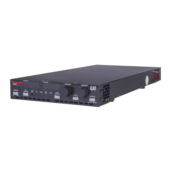
DLM 600W Series Power Supplies Operation Manual This manual covers models: DLM 5–75 DLM 8–75 DLM 10–60 DLM 20–30 DLM 40–15 DLM 60–10 DLM 80–7.5 DLM 150–4 DLM 300–2 M362161-01 Rev L www.programmablepower.com... - Page 5 From bench top supplies to rack-mounted industrial power subsystems, AMETEK Programmable Power is the proud manufacturer of Elgar, Sorensen, California Instruments and Power Ten brand power supplies. AMETEK, Inc. is a leading global manufacturer of electronic instruments and electromechanical devices with annualized sales of $2.5 billion.
- Page 6 DLM 600W Series service.ppd@ametek.comWeb: www.programmablepower.com This page intentionally left blank. viii M362161-01 Rev L...
-
Page 7: Important Safety Instructions
DLM 600W Series Important Safety Instructions Before applying power to the system, verify that your product is configured properly for your particular application. SECTION 1 Hazardous voltages may be present when covers are removed. Qualified personnel must use extreme caution when servicing this equipment. Circuit boards, test points, and output voltages also may be floating above (below) chassis ground. -
Page 8: Safety Symbols
DLM 600W Series Ensure that the AC power line ground is connected properly to the Power Rack input connector or chassis. Similarly, other power ground lines including those to application and maintenance equipment must be grounded properly for both personnel and equipment safety. Always ensure that facility AC input power is de-energized prior to connecting or disconnecting any cable. - Page 9 DLM 600W Series This page intentionally left blank. M362161-01 Rev L...
- Page 10 DLM 600W Series Product Family: DLM 600W Series Power Supplies Warranty Period: Five (5) Years WARRANTY TERMS AMETEK Programmable Power, Inc. (“AMETEK”), provides this written warranty covering the Product stated above, and if the Buyer discovers and notifies AMETEK in writing of any defect in material or workmanship within the applicable warranty period stated above, then AMETEK may, at its option: repair or replace the Product;...
- Page 11 DLM 600W Series This page intentionally left blank. M362161-01 Rev L xiii...
-
Page 12: Table Of Contents
DLM 600W Series CONTENTS SECTION 1 GENERAL DESCRIPTION .......... 1-1 Introduction .................... 1-1 General Description ................1-1 Features ....................1-2 Specifications ..................1-3 1.4.1 DLM Series Product Matrix ............1-3 1.4.2 Electrical Specifications .............. 1-4 1.4.3 General Characteristics ............. 1-5 1.4.4 Remote Analog Interface Characteristics ........ - Page 13 DLM 600W Series 2.11.1 Connecting Single Loads ............2-13 2.11.2 Connecting Multiple Loads ............ 2-15 2.12 Parallel Operation ................2-17 2.12.1 Parallel I/O Connector Pinout ..........2-19 2.12.2 Parallel I/O Interface Functions ..........2-19 2.13 Series Operation ................. 2-20 2.14 Special Application Warning ...............
- Page 14 DLM 600W Series Remote Programming ................4-6 4.4.1 Voltage–Source Programming of Output Voltage ...... 4-8 4.4.2 Voltage–Source Programming of Output Current ...... 4-9 4.4.3 Voltage–Source Programming of OVP ........4-10 4.4.4 Resistance Programming of Output Voltage ......4-11 4.4.5 Resistance Programming of Output Current ......4-12 4.4.6 Resistance Programming of OVP ..........
- Page 15 DLM 600W Series LIST OF FIGURES Figure 2-1. DLM 600W Series Outline Drawing ..........2-2 Figure 2-2. Rackmount Kit (Single Unit Option) ..........2-5 Figure 2-3. Rackmount Kit (Dual Unit Option) ..........2-7 Figure 2-4. Remote Sense Connector ............2-12 Figure 2-5.
- Page 16 DLM 600W Series xviii M362161-01 Rev L...
-
Page 17: General Description
SECTION 1 GENERAL DESCRIPTION Introduction The Sorensen DLM Series of 600W power supplies comprise a family of general purpose programmable supplies for rackmount and benchtop applications. The DLM 600W series consists of nine models, rated 5V/75A, 8V/75A, 10V/60A, 20V/30A, 40V/15A, 60V/10A, 80V/7.5A, 150V/4A, and 300V/2A. -
Page 18: Features
DLM 600W Series The outputs are isolated from the chassis GND. However, an internal I0MΩ bleeder resistor is connected from output return (-) to chassis ground. This allows operation with floating outputs, or with either the negative or positive terminal of the output referenced to chassis ground. -
Page 19: Specifications
DLM 600W Series • High resolution front panel controls for voltage and current (10–turn potentiometers), and OVP (20–turn trimmer potentiometer) • Preview switches for output voltage, current, and OVP to set parameters without disrupting load connections • Front panel OUTPUT switch for on/off control of output power •... -
Page 20: Electrical Specifications
DLM 600W Series 1.4.2 Electrical Specifications DLM Series Electrical Specifications Model DLM 5-75 DLM 8-75 DLM10-60 DLM20-30 DLM40-15 DLM60-10 DLM80-7.5 DLM150-4 DLM300-2 Output Rating: Output Voltage 0-5VDC 0-8VDC 0-10VDC 0-20VDC 0-40VDC 0-60VDC 0-80VDC 0-150VDC 0-300VDC Output Current 0-75ADC 0-75ADC 0-60ADC 0-30ADC 0-15ADC 0-10ADC... -
Page 21: General Characteristics
DLM 600W Series 1.4.3 General Characteristics AC Input Voltage Range: 90–132 VAC or 180–264 VAC; auto–ranging, no user setup required; single–phase, 2–wire plus ground AC Input Frequency Range: 47–63 Hz AC Input Current: 11A, maximum at 115 VAC; 6A, maximum at 230 VAC AC Input Power Factor: 0.6, typical at full load;... -
Page 22: Remote Analog Interface Characteristics
DLM 600W Series Fault Shutdown: Supervisory circuits monitor for abnormal operation of internal circuits: overtemperature, logic supply fault, paralleling interface connection fault, cooling fan fault, output converter driver fault, output converter overcurrent fault. A fault condition will result in shutdown of the output converter, and the output capacitors will be discharged with the downprogrammer. -
Page 23: Mechanical Characteristics
DLM 600W Series Digital Input Signals: Digital input control signals are provided for the following functions: LOCAL–LOCKOUT and ANALOG–CONTROL. The signals are active–low, with a logic–low output signal level of ≤ 0.8 VDC. The signals are not isolated from the negative output (return) terminal of the unit. -
Page 24: Regulatory Agency Compliance
Remote Analog Interface Connector: 25–position female subminiature–D connector. Remote Sense Connector: Two–position connector, Molex #39-30-0023. Paralleling Interface Connector: Two six–position connectors, Molex #43045-0602, for use with the Paralleling Cable, Sorensen part number DLMP1. 1.4.7 Regulatory Agency Compliance Units will comply with the requirements of the European Low Voltage Directive (IEC 61010-1:90+A1:92+A2:95) and EMC Directive (EN 61326:1998) as required for the CE mark. -
Page 25: Installation
SECTION 2 INSTALLATION Introduction The DLM Series power supply has been fully calibrated and tested prior to shipment; the unit is ready for immediate use upon receipt. However, when first unpacked, the unit should be inspected to ensure that no shipping damage has occurred. Initial Inspection Perform a visual inspection of the shipping container prior to accepting the package from the carrier. -
Page 26: Installation/Dimensional Drawing
DLM 600W Series Installation/Dimensional Drawing Refer to Figure 2-1 for dimensional and mounting information. Figure 2-1. DLM 600W Series Outline Drawing M362161-01 Rev L... -
Page 27: Rack Mounting
DLM 600W Series Rack Mounting A rackmount kit, Sorensen part number DLMRK, is an option that allows mounting either one unit (see Section 2.5.1) or two units side–by–side (see Section 2.5.2) in a standard 19" rack. The chassis is designed to permit units to be stacked one on top of the other without requiring clearance gaps between the units, or the use of slides. -
Page 28: Rack Mount Installation Of A Single Dlm Series 600W Unit
2.5.1 Rack Mount Installation of a Single DLM Series 600W Unit Follow the procedure below to install a single Sorensen DLM 600W Series power supply in a rack using the Rack Mount Kit, Sorensen part number DLMRK. Refer to Figure 2-2. -
Page 29: Figure 2-2. Rackmount Kit (Single Unit Option)
DLM 600W Series Figure 2-2. Rackmount Kit (Single Unit Option) M362161-01 Rev L... -
Page 30: Rack Mount Installation Of Two Dlm Series 600W Units
Rack Mount Installation of Two DLM Series 600W Units Follow the procedure below to install two (2) Sorensen DLM 600W Series power supplies in a rack using the Rack Mount Kit, Sorensen part number DLMRK . Refer to Figure 2-3. -
Page 31: Figure 2-3. Rackmount Kit (Dual Unit Option)
DLM 600W Series Figure 2-3. Rackmount Kit (Dual Unit Option) M362161-01 Rev L... -
Page 32: Input Power Requirements
DLM 600W Series Input Power Requirements The unit will operate from an AC power source rated at 90–132 VAC and 180–264 VAC, at 47–63 Hz. The AC input voltage range is automatically selected by the unit at power– up; no user setup is required. CAUTION Exceeding the maximum rated AC input voltage could result in damage to the unit. -
Page 33: Load Connections
DLM 600W Series Load Connections Low–voltage models rated 5V–60V have bus bars at the rear of the unit for connecting the load; refer to Figure 3-1. The bus bars are protected with a two–piece cover. The top portion of the cover is removable to allow access to the bus bar screws. In addition, the top portion has scored sections at the top and back that could be removed to provide a larger opening for wiring. -
Page 34: Wire Voltage Drop
DLM 600W Series Copper Area, Resistance, Resistance, Current Rating, A at 500A/cm Ω Ω Ω Ω /m at 20°C Ω Ω Ω Ω /m at 100°C 0.133 0.0013 0.0017 66.5 0.0837 0.0021 0.0028 41.9 0.0526 0.0033 0.0044 26.3 0.0331 0.0052 0.0069 16.6 0.0208... -
Page 35: Noise And Impedance Effects
DLM 600W Series 2.9.3 Noise and Impedance Effects To minimize noise pickup or radiation from load circuits, load wires and remote sense wires should be twisted–pair with minimum lead length. Shielding of the sense leads may be necessary in high noise environments. Even if noise is not a concern, the load and remote sense wires should be twisted–pairs to reduce coupling between them, which could impact the stability of the power supply. -
Page 36: Remote Sensing
DLM 600W Series 2.10.2 Remote Sensing Remote sensing is used during voltage–mode operation to compensate for the voltage drop across the load wires. It is selected by setting REM SNS of the SETUP switch, Position-1, to ON. Refer to Figure 4-1. A separate pair of wires is routed to measure the voltage at the load instead of the local connection at the output terminals. -
Page 37: Remote Sense (Rem Sns) Connector Pinout
DLM 600W Series 2.10.3 Remote Sense (REM SNS) Connector Pinout The REMOTE SENSE (REM SNS) connector is a 2–position connector, Molex #39-30-0023. The mating connector is Molex #39-01-3022; and its terminals are Molex #39-00-0056. The pinout is presented in Table 2–3. Pin Number Function Negative (–) Sense... -
Page 38: Figure 2-5. Single Load Connection With Local Sensing
DLM 600W Series Figure 2-5. Single Load Connection with Local Sensing *SETUP Switch Position-1, REM SNS, Set to ON Figure 2-6. Single Load Connection with Remote Sensing 2-14 M362161-01 Rev L... -
Page 39: Connecting Multiple Loads
DLM 600W Series 2.11.2 Connecting Multiple Loads When output voltage regulation is critical and multiple loads are connected to the power supply, it is important to connect each load independently to the terminals where the output voltage is sensed. Independent leads to each load will ensure that the load currents do not produce voltage drops in the connecting leads that could be mutually coupled between the loads. -
Page 40: Figure 2-8. Distribution Bus Connection With Remote Sensing
DLM 600W Series *SETUP Switch Position-1, REM SNS, Set to ON (1) For best performance use twisted shielded pair. Figure 2-8. Distribution Bus Connection with Remote Sensing 2-16 M362161-01 Rev L... -
Page 41: 2.12 Parallel Operation
DLM 600W Series 2.12 Parallel Operation Up to four power supplies of the same model can be connected in parallel. The paralleled supplies operate in a master/slave configuration, where the master controls the output voltage and total current, and provides control signals to the slaves to set their output current. -
Page 42: Figure 2-10. Parallel I/O Connector
Interconnect the master and slave units with the PARALLELING CABLE, Sorensen part number DLMP1. Either of the two rear panel PARALLEL I/O connectors can be used, as they are pinned out the same. Refer to Figure 2-10 for an illustration of the PARALLEL I/O connector and Table 2–4 for pinout information. -
Page 43: Parallel I/O Connector Pinout
DLM 600W Series 2.12.1 Parallel I/O Connector Pinout The PARALLEL I/O connector is a 6–position connector, Molex #43045-0602. The mating connector is Molex #43025-0600; and, its terminals are Molex #43030-0009. The pinout is presented in Table 2–4. Pin Number Function Parallel Drive Bus Parallel Drive Return Parallel Disable Bus... -
Page 44: 2.13 Series Operation
DLM 600W Series 2.13 Series Operation Multiple units of the same model can be connected in series to obtain a higher output voltage, within the limits of the 300V(PK) maximum float potential. The supplies are interconnected with the negative terminal of one supply being connected to the positive terminal of other. -
Page 45: Figure 2-12. Series Connection Of Units With Remote Sensing
DLM 600W Series Figure 2-12. Series Connection of Units with Remote Sensing M362161-01 Rev L 2-21... -
Page 46: 2.14 Special Application Warning
DLM 600W Series 2.14 Special Application Warning The DLM600 family of supply requires freewheeling and blocking diodes while driving inductive loads or batteries to protect the power supply from damage caused by power being fed back into the supply and from high voltage transients. 2.14.1 Suggested Procedure for Diode Selection The Peak Reverse Voltage ratings should be a minimum of 2-3 times the Power Supply... -
Page 47: Operation
SECTION 3 OPERATION Introduction The DLM Series power supplies have a full complement of controls, indicators, and connectors that allow the user to easily install, setup, and operate the unit. Controls and Indicators Refer to Figure 3-1 for an illustration of the front and rear panel controls and indicators. VOLTAGE Display: 3.5 digit, 7–segment LED display that normally indicates the output voltage. -
Page 48: Figure 3-1. Front And Rear Panel Views
DLM 600W Series Figure 3-1. Front and Rear Panel Views M362161-01 Rev L... - Page 49 DLM 600W Series OVP PREVIEW Switch: Momentary push–button switch for previewing the programmed setting of OVP. The programming signal is derived from the front panel control, the analog interface, or the GPIB interface, whichever has control. LOCAL(REMOTE) Switch: Momentary push–button switch for selecting local front–panel control while in GPIB remote operation, or toggling between the front–...
-
Page 50: Initial Functional Tests
DLM 600W Series PARALLEL I/O Connector: Two connectors used for configuring multiple power supplies for parallel operation with master/slave control. Both connectors have the same pinout and can be used interchangeably. The designation of master and slaves is selected with the SETUP switch. SETUP Switch: Eight–section switch for selecting remote sensing, slave unit, and 0–5 VDC or 0–10 VDC voltage ranges for programming and monitoring. -
Page 51: Constant-Voltage Mode Operation Check
DLM 600W Series 3.3.2 Constant–Voltage Mode Operation Check Ensure that the front panel POWER and OUTPUT switches are in the OFF position (switch buttons out). Connect a digital voltmeter (DVM) to measure the voltage at the output terminals Turn the VOLTAGE control on the front panel fully counter–clockwise. Turn the CURRENT control on the front panel fully clockwise. -
Page 52: Mode Of Operation Setup
DLM 600W Series Compare the DVM reading with the front panel display reading to verify accuracy of the front panel display for CURRENT. The DVM reading must be converted to current by multiplying the DVM reading by a conversion factor equal to the DC current rating of the shunt divided by the burden voltage rating of the shunt. -
Page 53: Constant-Current Mode Of Operation
DLM 600W Series 3.4.2 Constant–Current Mode of Operation The power supply will operate in constant–current mode whenever the load resistance times the current limit setting is less than the voltage setting. In this mode, the power supply maintains the output current precisely regulated to the current setting while the load voltage varies with load requirements. -
Page 54: Ovp Operation
DLM 600W Series OVP Operation The OVP monitor provides protection from overvoltage conditions that could be generated at the load due to improper adjustment of the output voltage or malfunction of the unit. Provisions are available to set the OVP threshold either with the front panel controls or remotely through the analog interface (or, through the optional GPIB interface). -
Page 55: Resetting Ovp
DLM 600W Series 3.5.2 Resetting OVP Perform the following to reset the OVP monitor if it has been activated: Reduce the power supply’s output voltage to below the OVP threshold. Ensure that the connections for the power and sense leads are correct. The OVP monitor is reset by toggling OFF and then back ON either of the following switches or signals: the OUTPUT switch, the POWER switch, the EXTERNAL–OFF signal of the REMOTE ANALOG INTERFACE, or through the... -
Page 56: And Ovp Preview Switches
DLM 600W Series 3.6.3 V/I and OVP PREVIEW Switches The V/I and OVP PREVIEW switches allow the front panel displays to show the programmed values for the output voltage, current, and OVP. They can be used to set the output parameters prior to turning on the output, and without disturbing the load connections. -
Page 57: Battery Charging
DLM 600W Series Battery Charging When using a power supply to charge a battery, the following precautions should be taken: Connect an isolation diode in series with one of the output terminals of the power supply. This diode will prevent discharge of the battery if the power supply were to be turned off. - Page 58 DLM 600W Series This page intentionally left blank. 3-12 M362161-01 Rev L...
-
Page 59: Advanced Operation
SECTION 4 ADVANCED OPERATION Introduction The DLM Series power supplies provide extended configuration and interface capabilities to allow them to be adapted for special applications. The SETUP switch allows selection of programming and monitor voltage ranges, remote sensing, or slave mode of operation. -
Page 60: Setup Switch Functions
DLM 600W Series Switch Position Function OFF (Down) Position ON (Up) Position REM SNS Local Sense Remote Sense Slave Master or Standalone Slave Not Used IMON, 10V Select 0–5V Range 0–10V Range VMON, 10V Select 0–5V Range 0–10V Range OVP, 10V Select 0–5V Range 0–10V Range... -
Page 61: Remote Analog Interface
DLM 600W Series REMOTE ANALOG INTERFACE The REMOTE ANALOG INTERFACE provides a means to remotely control and monitor the operation of the power supply. Refer to Figure 4-2 for an illustration of the connector, and Table 4–2 for pinout information. Figure 4-2. -
Page 62: Remote Analog Interface Functions
DLM 600W Series 4.3.2 REMOTE ANALOG INTERFACE Functions The REMOTE ANALOG INTERFACE provides control signals for programming output voltage, current, and OVP, monitoring the output voltage and current, and controlling the operational state of the power supply. The following paragraphs describe the functions of the various signals. - Page 63 DLM 600W Series Analog Output Signals REMOTE VOLTAGE MONITOR: Pin-19, readback of the output voltage is provided with a 0–5 VDC or 0–10 VDC signal (user selectable with SETUP switch) indicating 0–100% of full scale output. Signal is referenced to Pin-8, and is not isolated from the negative (return) output of the unit.
-
Page 64: Remote Programming
DLM 600W Series REMOTE RESISTANCE VOLTAGE–PROGRAMMING RETURN: Pin-20, signal return for REMOTE RESISTANCE VOLTAGE–PROGRAMMING OUTPUT. Signal is not isolated from the negative (return) output of the unit. REMOTE RESISTANCE CURRENT–PROGRAMMING OUTPUT: Pin-22 connected to Pin-10, REMOTE CURRENT PROGRAMMING INPUT, with an adjustable resistance of 0–5 kΩ... -
Page 65: Table 4-3. Remote Programming Options
DLM 600W Series Table 4–3 presents the options for remote control operation; pin numbers refer to the REMOTE ANALOG INTERFACE connector. Mode of Analog–Control Local–Lockout Local/Remote Power–Up Operation Signal, Pin-1 Signal, Pin-24 Toggling State Remote Only Remote Local Only Open Open Local Local/Remote... -
Page 66: Voltage-Source Programming Of Output Voltage
DLM 600W Series 4.4.1 Voltage–Source Programming of Output Voltage Refer to Figure 4-3 for setting up voltage–source programming of the output voltage. Set Position-8 of the SETUP switch to OFF for 0–5 VDC programming range. Set Position-8 of the SETUP switch to ON for 0–10 VDC programming range. Connect the external programming voltage source to the REMOTE ANALOG INTERFACE connector, with positive to Pin-9 and negative to Pin-12. -
Page 67: Voltage-Source Programming Of Output Current
DLM 600W Series 4.4.2 Voltage–Source Programming of Output Current Refer to Figure 4-4 for setting up voltage–source programming of the output current. Set Position-7 of the SETUP switch to OFF for 0–5 VDC programming range. Set Position-7 of the SETUP switch to ON for 0–10 VDC programming range. Connect the external programming voltage source to the REMOTE ANALOG INTERFACE connector, with positive to Pin-10 and negative to Pin-12. -
Page 68: Voltage-Source Programming Of Ovp
DLM 600W Series 4.4.3 Voltage–Source Programming of OVP Refer to Figure 4-5 for setting up voltage–source programming of OVP. Set Position-6 of the SETUP switch to OFF for 0–5 VDC programming range. Set Position-6 of the SETUP switch to ON for 0–10 VDC programming range. Connect the external programming voltage source to the REMOTE ANALOG INTERFACE connector, with positive to Pin-3 and negative to Pin-12. -
Page 69: Resistance Programming Of Output Voltage
DLM 600W Series 4.4.4 Resistance Programming of Output Voltage Refer to Figure 4-6 for setting up resistance programming of the output voltage. Set Position-8 of the SETUP switch to OFF for 0–5 VDC programming range Connect the external programming resistance, 0–5 kΩ, to the REMOTE ANALOG INTERFACE connector, from Pin-20 to Pin-21. -
Page 70: Resistance Programming Of Output Current
DLM 600W Series 4.4.5 Resistance Programming of Output Current Refer to Figure 4-7 for resistance programming of the output current. Set Position-7 of the SETUP switch to OFF for 0–5 VDC programming range. Connect the external programming resistance, 0–5 kΩ, to the REMOTE ANALOG INTERFACE connector, from Pin-23 to Pin-22. -
Page 71: Resistance Programming Of Ovp
DLM 600W Series 4.4.6 Resistance Programming of OVP Refer to Figure 4-8 for setting up resistance programming of OVP. Set Position-6 of the SETUP switch to OFF for 0–5 VDC programming range. Connect the external resistance, 0–5 kΩ, to the REMOTE ANALOG INTERFACE connector, from Pin-17 to Pin-16. -
Page 72: External-Off Control
DLM 600W Series EXTERNAL–OFF Control The EXTERNAL–OFF control input provides the same functionality as the OUTPUT switch on the front panel. When asserted, it will turn off the output converter, discharge the output capacitors with the downprogrammer, and reset the OVP and FAULT monitors. -
Page 73: External-Off With Auxiliary 5 Vdc Output
DLM 600W Series 4.5.2 EXTERNAL–OFF with AUXILIARY 5 VDC OUTPUT The internal AUXILIARY 5 VDC OUTPUT of the REMOTE ANALOG INTERFACE can be used as the voltage source to drive the EXTERNAL OFF input. Because the 5 VDC source is referenced to the other signals of the analog interface, opto–isolation would be lost. -
Page 74: Remote Digital Status Signals
DLM 600W Series Remote Digital Status Signals Digital signals are available for remote monitoring the operational status of the unit. Refer to Table 4–5 for information on the characteristics of the signals. REMOTE ANALOG Logic Levels (with no Output INTERFACE Connections signal output current) Status Signal Resistance... -
Page 75: Maintenance
SECTION 5 MAINTENANCE Introduction This section provides information about troubleshooting, maintenance, and calibration. Troubleshooting If the power supply appears to be operating improperly, determine whether the power supply, load, or external control/programming circuits are the cause. Configure the unit for basic front panel controlled operation, and perform the checks of Section 3.3, Initial Functional Tests to determine if the problem is with the supply. -
Page 76: Table 5-1. Troubleshooting Guide
DLM 600W Series SYMPTOM CHECK ACTION No output; all displays and Is the utility power present? Connect power indicators are blank Is the AC input power cord Check continuity; replace defective? if necessary Unit starts but there is no Is the AC input voltage within Connect to appropriate output;... -
Page 77: Fuse Ratings
DLM 600W Series Fuse Ratings There are no user replaceable fuses in the power supply. Internal fuses are sized for fault isolation, and, if they were open, would indicate that service is required. The internal fuses are to be checked and replaced by qualified technical personnel. Refer to Table 5–2 for a listing of the fuses. -
Page 78: Figure 5-1. Main Pwa Location Of Test Points And Potentiometers
DLM 600W Series There is some interaction of the adjustments for offset and range of the output voltage and current. Perform the offset adjustments before the range adjustments. It may take several iterations to accurately make both adjustments. There is some variation of the output current at high current levels because of the temperature coefficient of the internal current shunts. -
Page 79: Internal Reference Adjustment
DLM 600W Series 5.5.1 Internal Reference Adjustment Use the following procedure to adjust the internal –5.0 VDC reference: Connect a voltmeter from J14-4, positive lead, to J14-6, negative lead. Adjust potentiometer R379 for a reading on the voltmeter of –5.000 VDC. 5.5.2 Output Voltage Offset Adjustment Calibration of the output voltage is done using remote control through the REMOTE... -
Page 80: Output Current Offset Adjustment
DLM 600W Series 5.5.4 Output Current Offset Adjustment Calibration of the output current is done using remote control through the REMOTE ANALOG INTERFACE. Use the following procedure to adjust the output current offset: Connect a DC shunt across the output terminals of the unit. Connect a jumper from Pin-1 to Pin-6 of the REMOTE ANALOG INTERFACE connector to enable remote control. -
Page 81: Voltage Display Adjustment
DLM 600W Series 5.5.6 Voltage Display Adjustment Use the following procedure to calibrate the voltage display: Connect a voltmeter across the output terminals of the power supply. Adjust the front panel CURRENT and OVP controls to fully clockwise. Turn the OUTPUT switch on. Adjust the front panel VOLTAGE control for an output voltage equal to 100% of full scale. - Page 82 DLM 600W Series This page intentionally left blank. M362161-01 Rev L...
Need help?
Do you have a question about the DLM 5–75 and is the answer not in the manual?
Questions and answers