Table of Contents
Advertisement
Quick Links
Elgar Electronics Corporation
9250 Brown Deer Road
San Diego, CA 92121-2294
1-800-73ELGAR (1-800-733-5427)
Tel: (858) 450-0085
Fax: (858) 458-0267
Email: sales@elgar.com
This document contains information proprietary to Elgar Electronics Corporation. The information contained herein is
not to be duplicated or transferred in any manner without prior written permission from Elgar Electronics Corporation
November 7, 2007
SFA Series
DC Power Supplies
Operation Manual
©2007 by Elgar Electronics Corporation
www.elgar.com
Document No. M550292-01 Rev C
.
Advertisement
Table of Contents

Related Manuals for Sorensen SFA Series


Summary of Contents for Sorensen SFA Series
- Page 1 SFA Series DC Power Supplies Operation Manual Elgar Electronics Corporation 9250 Brown Deer Road San Diego, CA 92121-2294 1-800-73ELGAR (1-800-733-5427) Tel: (858) 450-0085 www.elgar.com Fax: (858) 458-0267 Email: sales@elgar.com ©2007 by Elgar Electronics Corporation This document contains information proprietary to Elgar Electronics Corporation. The information contained herein is...
- Page 3 • that the Sorensen QA seal and nameplates have not been altered or removed and the equipment has not been repaired or modified by anyone other than EEC-authorized personnel. This warranty is exclusive and in lieu of all other warranties, expressed or implied, including, but not limited to, implied warranties of merchantability and fitness of the product to a particular purpose.
- Page 4 This page intentionally left blank. M550292-01 Rev C...
-
Page 5: Safety Notice
SAFETY NOTICE Before applying power to the system, verify that the Power Rack is configured properly for your particular application. Hazardous voltages may be present when covers are removed. Qualified personnel must use extreme caution when servicing this equipment. Circuit boards, test points, and output voltages also WARNING may be floating above (below) chassis ground. - Page 6 This page intentionally left blank. M550292-01 Rev C...
-
Page 7: Fcc Notice
FCC NOTICE This equipment has been tested and found to comply with the limits for a Class A digital device, pursuant to part 15 of the FCC Rules. These limits are designed to provide reasonable protection against harmful interference when equipment operated commercial... - Page 8 This page intentionally left blank. M550292-01 Rev C...
-
Page 9: About This Manual
ABOUT THIS MANUAL This manual has been written expressly for the Sorensen Series of power supplies that have been designed and certified to meet the Low Voltage and Electromagnetic Compatibility Directive Requirements of the European Community. Since the Low Voltage Directive is to ensure the safety of the equipment... - Page 10 This page intentionally left blank. viii M550292-01 Rev C...
-
Page 11: Table Of Contents
General Description..................1-1 Technical Specifications .................. 1-1 1.2.1 Environmental Characteristics............. 1-1 1.2.2 Electrical Characteristics ..............1-2 1.2.3 SFA Series Voltage and Current Specifications ........1-4 1.2.4 Physical Characteristics ..............1-4 SECTION 2 INSTALLATION..............2-1 Inspection ......................2-1 Contents of Shipment ..................2-1 Input/Output Connections................ - Page 12 Contents Sorensen SFA Series 3.1.1 Shaft Lock (Option) ................3-4 Local Operation ....................3-4 3.2.1 Floating and Polarized Output ..............3-5 3.2.2 Initial Setup...................3-5 3.2.3 Current Mode Operation...............3-6 3.2.4 Overcurrent Protection .................3-6 3.2.5 Analog Control Connector (J1) .............3-7 Remote Current Programming ...............3-11 Remote Sensing.....................3-12 Remote Output On/Off Control...............3-14...
- Page 13 Table 5–2. Fuse Values ....................5-3 LIST OF FIGURES Figure 2–1. SFA Series Outline Drawing, 3U Models, 5kW to 15kW......2-9 Figure 2–2. SFA Series Outline Drawing, 6U Models, 20kW to 30kW......2-10 Figure 3–1. Front Panel Controls and Indicators (3U model shown) ......3-1 Figure 3–2.
- Page 14 This page intentionally left blank. M550292-01 Rev C...
-
Page 15: Overview
A variety of user interfaces are available, ranging from manual front–panel control and standard non–isolated remote analog control, to optional GPIB or isolated remote analog control. TECHNICAL SPECIFICATIONS The following sections provide environmental, electrical, and physical characteristics for the SFA Series power supplies. 1.2.1 NVIRONMENTAL HARACTERISTICS Note: The Series power supplies are intended for indoor use only. - Page 16 Sorensen SFA Series Overview 1.2.2 LECTRICAL HARACTERISTICS Parameter Specification Input Power Voltage (Standard) 208/220 VAC±10% (tested to 187-242 VAC) 380/400 VAC±10% (tested to 342-440 VAC) Voltage (Options) 440/480 VAC±10% (tested to 396-528 VAC) Frequency 47 to 63 Hz 3–phase, 3–wire plus ground. Not phase rotation Phases sensitive.
- Page 17 Sorensen SFA Series Overview Parameter Specification Efficiency 87% typical at full load, nominal line Remote Programming Accuracy Constant Current ±0.8% of full-scale output Overcurrent Protection ±1% of full-scale output Resistive Constant Current (0-100%) 0–5 kΩ Voltage Constant Current (0-100%) 0–5 VDC or 0–10 VDC Overcurrent Protection 0–5.5 VDC...
- Page 18 Sorensen SFA Series Overview SFA S 1.2.3 ERIES OLTAGE AND URRENT PECIFICATIONS Ratings Voltage 5 kW 10 kW 15 kW 20 kW 25 kW 30 kW 0-60V 0-83A 0-167A 0-250A 0-333A 0-417A 0-500A 0-100V 0-50A 0-100A 0-150A 0-200A 0-250A 0-300A...
-
Page 19: Installation
Depending on the model, configuration, and options available for your SFA Series power supply, the ship kit may include additional parts and accessories. At a minimum, the ship kit that accompanies your SFA Series power supply includes the following items: •... -
Page 20: Input/Output Connections
High voltage present! Risk of electrical shock. Do not remove cover. Refer to qualified service personnel. Table 2–1 lists all external connections for the SFA Series models. Table 2–2 and Table 2–3 provide input and output connection descriptions by power supply type. -
Page 21: Location And Mounting
Sorensen SFA Series Installation LOCATION AND MOUNTING WARNING! To reduce the risk of fire or electrical shock, install the SFA Series unit in a temperature and humidity controlled indoor area, free of conductive contaminants. CAUTION! The unit should be provided with proper ventilation. The rear and both sides of the unit should be free of obstructions. -
Page 22: Table 2-1. 5Kw To 15Kw And 20Kw To 30Kw Series Input/Output Connectors
The slides can be mounted to the chassis with this spring oriented on the top or the bottom of the slide. Table 2–1 provides details of the SFA Series input and output connectors and their functions. Connector... -
Page 23: Wire Size
Sorensen SFA Series Installation WIRE SIZE Care must be taken to properly size all conductors for the input and output of the power supply. The tables below will assist in determining the appropriate wire size for both the input and output connections Table 2–4 below gives minimum recommended wire size. -
Page 24: Wire Gauge Selection
The same engineering rules apply whether going into or out of an electrical device. Thus, this guide applies equally to the input cable and output cable for this Sorensen instrument and application loads. Power cables must be able to safely carry maximum load current without overheating or causing insulation destruction. -
Page 25: Table 2-5 Recommended Wire Gauge Selection Guide
Sorensen SFA Series Installation Column 1 Column 2 Column 3 Column 4 Size Amperes Ohms/100 Feet IR Drop/100 Feet (AWG) (Maximum) (One Way) (Column 2 x Column 3) 0.257 3.85 0.162 3.24 0.102 3.06 0.064 2.56 0.043 2.36 0.025 1.75 0.015... -
Page 26: Load Considerations
In order to reset the unit, the input standby switch, will need to be cycled on and off. OUTLINE DRAWINGS Figure 2–1 and Figure 2–2, next, show the outlines and overall dimensions of the 3U and 6U models of the SFA Series product line. M550292-01 Rev C... -
Page 27: Figure 2-1. Sfa Series Outline Drawing, 3U Models, 5Kw To 15Kw
Sorensen SFA Series Installation Slide Mounting 8-32UNC-2B 4PL Nearside 3PL Far side Figure 2–1. SFA Series Outline Drawing, 3U Models, 5kW to 15kW M550292-01 Rev C... -
Page 28: Figure 2-2. Sfa Series Outline Drawing, 6U Models, 20Kw To 30Kw
Installation Sorensen SFA Series Slide Mounting 8-32UNC-2B 6PL Nearside 7PL Far side Figure 2–2. SFA Series Outline Drawing, 6U Models, 20kW to 30kW 2-10 M550292-01 Rev C... -
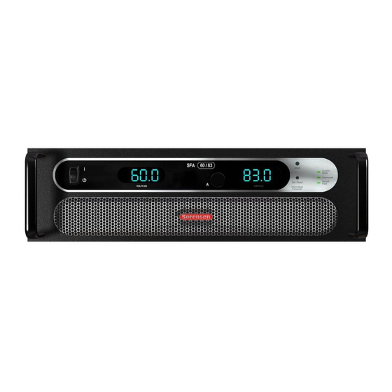
Page 29: Operation
OPERATION CONTROLS AND INDICATORS Refer to Figure 3–1 and the corresponding descriptions below for an explanation of front panel controls and indicators on the SFA Series power supply. Figure 3–1. Front Panel Controls and Indicators (3U model shown) Voltage Display: 3½ digit green LED display indicates the DC output voltage of the supply. - Page 30 Operation Sorensen SFA Series CURRENT MODE Indicator: Green LED lights when in the constant–current mode of operation. When in the constant–current mode, the output current will regulate to the set value and the output voltage will vary with the load. This is the normal operating mode for the SFA.
-
Page 31: Figure 3-2. Rear Panel Connectors (3U Model Shown)
PARALLEL IN connector (see Section 3.8). RS232 Connector: Optional RJ-11 connector for remote control. Dipswitch: Eight–position dipswitch to configure an SFA Series unit with an IEEE option. GPIB Connector: Optional connector for remote control. AC Input Bus Bars: Connection for 3-phase AC and Ground. -
Page 32: Shaft Lock (Option)
Never completely loosen the cone nut, or remove the shaft lock from the chassis. LOCAL OPERATION The SFA Series power supply is shipped from the factory configured for local current control and local voltage sensing. The ANALOG CONTROL connector is supplied with a mating connector with remote ON/OFF jumpered for ON (terminal 5 shorted to terminal 6). -
Page 33: Floating And Polarized Output
Sorensen SFA Series Operation This section provides an overview of front panel operation and initial functional tests of the power supply. 3.2.1 LOATING AND OLARIZED UTPUT The SGA Series supply can be set up for a Positive or Negative supply, as well as standard operation as a floating output supply. -
Page 34: Current Mode Operation
URRENT PERATION When the supply is in the Current Mode (the default mode for the SFA series), the output current of the supply is controlled by the Current knob on the front panel or by the remote current input (see Section 3.3). To verify operation in current mode, follow the steps below: 1. -
Page 35: Analog Control Connector (J1)
Sorensen SFA Series Operation 4. Press and hold the Set/Reset Overcurrent Protection pushbutton on the front panel and observe the reading on the current display. This is the present setting of the OCP limit. The factory default setting is approximately 110% of the maximum rated output of the supply. -
Page 36: Figure 3-4. Analog Control Connector (J1) Pin-Out
Operation Sorensen SFA Series CAUTION! This option is not intended to allow operation of the power supply at excessive voltages. Refer to Section 2 INSTALLATION for maximum terminal voltages. Following are Figure 3–4 with the connector's pin-out diagram, and Table 3–1 with ANALOG CONTROL connector designations and functions: Figure 3–4. - Page 37 Sorensen SFA Series Operation Schematic Electrical Functional Description Symbol Chars. Zout ~ Output current monitor. 0-10 VDC equals 0-100% rated current. I MON 100Ω Minimum load resistance 10kΩ. Not Used Not Used Remote current programming using a 0-5 VDC source.
-
Page 38: Table 3-1. Analog Control Connector (J1), Designations And Functions
Operation Sorensen SFA Series Schematic Electrical Functional Description Symbol Chars. Zout ~ Output voltage monitor. 0-10 VDC equals to 0-100% rated V MON 100Ω voltage. Minimum load resistance 10kΩ. Not Used Not Used 1 milliamp current source for remote current programming ~ 10.8V... -
Page 39: Remote Current Programming
Sorensen SFA Series Operation REMOTE CURRENT PROGRAMMING Remote current programming is used for applications that require the output current be programmed (controlled) from a remote source. An external resistance or external voltage source may be used as a programming device. -
Page 40: Remote Sensing
Operation Sorensen SFA Series model, each 100 millivolts of programming voltage equals 3 amps of output current. See Figure 3–6 for connection requirements. 16 IP 10V COM 6 IP 5V 10 23 IP RTN 0-5 VDC 0-10 VDC VOLTAGE VOLTAGE... -
Page 41: Figure 3-7. Remote Sensing Operation At The Load
Sorensen SFA Series Operation Figure 3–7. Remote Sensing Operation at the Load M550292-01 Rev C 3-13... -
Page 42: Remote Output On/Off Control
Operation Sorensen SFA Series REMOTE OUTPUT ON/OFF CONTROL Remote on/off control may be accomplished by contact closure or by an isolated external AC/DC or TTL/CMOS voltage source. 1. Remote on/off by contact closure. Output is on when contacts (J1-5 and J1-6) are closed. See Figure 3–8 for connection requirements. -
Page 43: Remote Overcurrent Setpoint
Sorensen SFA Series Operation 14 ISO TTL/CMOS ISO RTN 2 Figure 3–10. Remote On/Off Using Isolated TTL/CMOS Voltage Supply REMOTE OVERCURRENT SETPOINT CAUTION! Do not program the remote overcurrent set point greater than 10% (5.5V) above the power supply rated current (except as noted) as internal power supply damage may occur. -
Page 44: Remote Shutdown (S/D)
Operation Sorensen SFA Series an OCP externally, apply a 10.5–13.3 VDC signal to J1-3 for a minimum of four (4) seconds. REMOTE SHUTDOWN (S/D) A remote +12 VDC voltage can be connected externally between terminals J1- 18 (S/D Fault) and J1-24 (COM) to disable, i.e., shut down the output of the power supply. -
Page 45: Series Operation
Non-isolated Analog programming supplies. (600V for supplies with the Isolated Analog option installed). If a higher output voltage range is required, contact the Sorensen Sales Department or Customer Service for availability. The maximum allowable current for a series string of power supplies is the rated output current of a single supply in the string. - Page 46 Operation Sorensen SFA Series This page intentionally left blank. 3-18 M550292-01 Rev C...
-
Page 47: Verification And Calibration
SECTION 4 VERIFICATION AND CALIBRATION INTRODUCTION This section provides verification and calibration procedures for the standard SFA Series power supplies and isolated analog control (option). 4.1.1 ERIFICATION AND ALIBRATION YCLE It is recommended that the power supply be calibrated and/or verified once each year of operation. -
Page 48: Standard Verification And Calibration Procedure
Figure 4–1. Precision Current Shunt STANDARD VERIFICATION AND CALIBRATION PROCEDURE All calibration potentiometers can be adjusted through access holes in the top cover of the SFA Series unit. It is not necessary to remove the top cover to perform the calibration procedures. 4.2.1 URRENT 1. -
Page 49: Resistor Programming Current Sources
ISOLATED ANALOG (OPTION) VERIFICATION AND CALIBRATION PROCEDURE All calibration potentiometers can be adjusted through access holes in the top cover of the SFA Series unit. It is not necessary to remove the top cover to perform the calibration procedures. M550292-01 Rev C... -
Page 50: Current Mode
Sorensen SFA Series 4.3.1 URRENT 1. Set the SFA series unit to operate in remote current programming mode using an external 0-5 Vdc voltage source as shown in Figure 3–6 in Section 3.3 Remote Current Programming. 2. Attach a precision meter across the shunt Kelvin terminals. -
Page 51: Figure 4-2. Potentiometer Locations
Sorensen SFA Series Verification and Calibration STANDARD CALIBRATION ADJUSTMENT R71 = IPRES (1mA) Adjust R87 = Voltage Meter Adjust R86 = Current Meter Adjust R69 = 100% Current Adjust R55 = Zero Current Adjust ISOLATED ANALOG (OPTION) CALIBRATION ADJUSTMENT R86 = Voltage Meter Adjust... - Page 52 Verification and Calibration Sorensen SFA Series This page intentionally left blank. M550292-01 Rev C...
-
Page 53: Maintenance
PREVENTIVE MAINTENANCE No routine maintenance on the SFA Series is required, aside from periodic cleaning of the unit when needed: • Once a unit is removed from service, vacuum all air vents, including the front panel grill. -
Page 54: Table 5-1. Recommended Annual Inspection
Maintenance Sorensen SFA Series An annual inspection of the SFA Series unit is recommended. Table 5–1 lists the visual inspection checks to be performed, and the corrective action to be taken. Table 5–1. Recommended Annual Inspection Item Inspect For Corrective Action... -
Page 55: Fuses
Sorensen SFA Series Maintenance FUSES There are no user replaceable components in the power supply. WARNING! Only properly trained and qualified personnel should remove the cover from the power supply. Service, fuse verification, and connection of wiring to the chassis must be accomplished at least five minutes after power has been removed via external means;... - Page 56 Maintenance Sorensen SFA Series This page intentionally left blank. M550292-01 Rev C...
- Page 57 INDEX Preventive, 5-1 Master/Slave Operation, 3-15 Mounting Hardware, 2-3 Circuit Breaker Requirements, 2-2 Controls and Indicators, 3-1 Analog Control (J1), 3-6 Current Mode Operation Operation, 3-4 Current Mode, 3-4 Verification and Calibration, 4-2 Local, 3-4 Master/Slave, 3-15 Parallel, 3-15 Remote Current Programming, 3-10 Fuses, 5-3 Remote Output On/Off Control, 3-13 Remote Overvoltage Setpoint, 3-14...
- Page 58 Index Sorensen SFA Series Ripple, 1-3 Voltage, 1-3 Safety Symbols, iv Series Operation, 3-16 Setup, 3-4 Ventilation, 2-2 Shaft Lock, 3-3 Verification and Calibration, 4-2 Specifications, 1-1 Current Mode, 4-2 Current, 1-3 Electrical Characteristics, 1-2 Environmental Characteristics, 1-1 Noise, 1-3...
Need help?
Do you have a question about the SFA Series and is the answer not in the manual?
Questions and answers