
Related Manuals for Fronius WF 25i REEL R/SA/2R/G/W


Summary of Contents for Fronius WF 25i REEL R/SA/2R/G/W
- Page 1 Operating Instructions WF 25i REEL R /SA/2R/G/W Operating Instructions 42,0426,0160,EN 018-01102024...
-
Page 3: Table Of Contents
Contents Safety rules Explanation of safety notices General Proper use Environmental conditions Obligations of the operator Obligations of personnel Mains connection Protecting yourself and others Danger from toxic gases and vapours Danger from flying sparks Risks from mains current and welding current Meandering welding currents EMC Device Classifications EMC measures... - Page 4 Disposal Troubleshooting General Safety LED indicators in the event of a fault Fault diagnosis Technical data WF 25i REEL R /SA/2R/G/W...
-
Page 5: Safety Rules
Safety rules Explanation of DANGER! safety notices Indicates immediate danger. ▶ If not avoided, death or serious injury will result. WARNING! Indicates a potentially hazardous situation. ▶ If not avoided, death or serious injury may result. CAUTION! Indicates a situation where damage or injury could occur. ▶... -
Page 6: Proper Use
Proper use The device is to be used exclusively for its intended purpose. The device is intended solely for the welding processes specified on the rating plate. Any use above and beyond this purpose is deemed improper. The manufacturer shall not be held liable for any damage arising from such usage. Proper use includes: carefully reading and following all the instructions given in the operating in- structions... -
Page 7: Mains Connection
Before leaving the workplace, ensure that people or property cannot come to any harm in your absence. Mains connec- Devices with a higher rating may affect the energy quality of the mains due to tion their current consumption. This may affect a number device types in terms of: Connection restrictions Criteria with regard to the maximum permissible mains impedance Criteria with regard to the minimum short-circuit power requirement... -
Page 8: Danger From Toxic Gases And Vapours
Danger from tox- The fumes produced during welding contain harmful gases and vapours. ic gases and va- Welding fumes contain substances that cause cancer, as stated in Monograph pours 118 of the International Agency for Research on Cancer. Use at-source extraction and a room extraction system. If necessary, use a welding torch with an integrated extraction device. -
Page 9: Risks From Mains Current And Welding Current
Do not carry out welding on containers that are being or have been used to store gases, propellants, mineral oils or similar products. Residues pose an explosive hazard. Risks from mains An electric shock is potentially life threatening and can be fatal. current and Do not touch live parts either inside or outside the device. -
Page 10: Meandering Welding Currents
If work on live parts is required, have a second person switch off the main switch at the right moment. Meandering If the following instructions are ignored, meandering welding currents can devel- welding currents op with the following consequences: Fire hazard Overheating of parts connected to the workpiece Damage to ground conductors Damage to device and other electrical equipment... -
Page 11: Emf Measures
Supporting measures for avoidance of EMC problems: Mains supply If electromagnetic interference arises despite the correct mains connec- tion, additional measures are necessary (e.g. use of a suitable line filter) Welding power-leads must be kept as short as possible must be laid close together (to avoid EMF problems) must be kept well apart from other leads Equipotential bonding Earthing of the workpiece... -
Page 12: Requirement For The Shielding Gas
Welding machines for work in areas with increased electrical risk (e.g. near boil- ers) must carry the 'Safety' sign. However, the welding machine must not be loc- ated in such areas. Risk of scalding from escaping coolant. Switch off cooling unit before discon- necting coolant flow or return lines. -
Page 13: Danger From Escaping Shielding Gas
Never hang a welding torch on a shielding gas cylinder. Never touch a shielding gas cylinder with an electrode. Risk of explosion - never attempt to weld a pressurised shielding gas cylinder. Only use shielding gas cylinders suitable for the application in hand, along with the correct and appropriate accessories (regulator, hoses and fittings). -
Page 14: Safety Measures In Normal Operation
After transporting the device, the device must be visually inspected for damage before commissioning. Any damage must be repaired by trained service techni- cians before commissioning the device. Safety measures Only operate the device when all safety devices are fully functional. If the safety in normal opera- devices are not fully functional, there is a risk of tion... -
Page 15: Safety Inspection
(e.g. relevant product standards of the EN 60 974 series). Fronius International GmbH hereby declares that the device is compliant with Directive 2014/53/EU. The full text on the EU Declaration of Conformity can be found at the following address: http://www.fronius.com Devices marked with the CSA test mark satisfy the requirements of the relevant standards for Canada and the USA. - Page 16 Text and illustrations were accurate at the time of printing, subject to change. We are grateful for suggestions for improvement and information regarding any discrepancies in the operating instructions.
-
Page 17: General
Proper use The device is designed exclusively for wirefeeding in automated MIG/MAG weld- ing applications in conjunction with Fronius system components. Any use above and beyond this purpose is deemed improper. The manufacturer shall not be held liable for any damage arising from such usage. -
Page 18: Application Example
Application ex- ample (12) (13) (10) (11) (14) (15) (1) (2) Welding machine (10) Wirefeeding hose from unreel- Robot interface ing wirefeeder to robot Cooling unit wirefeeder Robot control (11) Interconnecting hosepack Welding wire drum (12) Robot wirefeeder Wirefeeding hose to the un- (13) Torch hosepack reeling wirefeeder... -
Page 19: Warning Notices On The Device
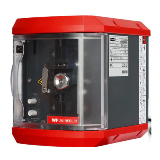
40,0006,3035 WF 25i REEL R /sa/2R/G/W Part No.: 4,049,039,850 www.fronius.com 24060701 Ser.No.: IEC 60 974-5/-10 Cl.A IP 21 100 - 240 V 1.7 - 0.7 A... - Page 20 Keep hands, hair, clothing and tools away from moving parts. For ex- ample: Cogs Feed rollers Wire spools and welding wires Do not reach into the rotating cogs of the wire drive or into rotating drive components. Covers and side panels may only be opened/removed while mainten- ance or repair work is being carried out.
-
Page 21: Description Of The Warning Notices On The Device
Description of For certain device versions, warning notices are affixed to the device. the warning no- tices on the The arrangement of the symbols may vary. device Warning! Attention! The symbols represent possible dangers. Drive rollers can injure fingers. The welding wire and drive parts are live during operation. Keep hands and metal objects away! An electric shock can be fatal. - Page 22 Use forced-air ventilation or a local extraction system to remove welding fumes. Remove welding fumes with a fan. Welding sparks can cause an explosion or fire. Keep flammable materials away from the welding process. Never weld close to flammable materials. Welding sparks can cause a fire.
-
Page 23: Controls, Connections And Mechanical Components
Controls, connections and mechanical compon- ents Safety WARNING! Danger from incorrect operation and work that is not carried out properly. This can result in serious personal injury and damage to property. ▶ All the work and functions described in this document must only be carried out by technically trained and qualified personnel. -
Page 24: Control Panel
2-roller drive Wire feed speed potentiometer 1 - 15 m/min (39.4 - 590.6 ipm.) for wire threading and wire retraction Torque potentiometer 10 - 100% (10% = 5 N, 100% = 50 N) Factory setting: 40% Opening for optional sash lock Control panel Robot control connection (option) - Page 25 Press and hold the button After about 0.1 seconds, the wirefeeder reaches the wire speed value set on the wire speed potentiometer, and this value is then used for wire retraction NOTE! Do not allow long lengths of wire electrode to be retracted, as the wire electrode is not wound onto the wire spool or the welding wire drum when retracted.
-
Page 26: Fitting The Wire-Feed Unit
Fitting the wire-feed unit Fitting the WARNING! wirefeeder Danger from electric current. This can result in serious personal injury and damage to property. ▶ Before starting work, switch off all the devices and components involved and disconnect them from the grid. ▶... -
Page 27: Inserting/Replacing Feed Rollers
Inserting/replacing feed rollers Safety WARNING! Danger from electric current. This can result in serious personal injury and damage to property. ▶ Before starting work, switch off all the devices and components involved and disconnect them from the grid. ▶ Secure all the devices and components involved to prevent unintentional re- starting. - Page 29 CAUTION! Danger from exposed feed rollers. Risk of crushing. ▶ Always fit the protective cover of the 2-roller drive after changing feed rollers.
-
Page 30: Feeding In The Wire Electrode
Feeding in the wire electrode Insulated rout- CAUTION! ing of wire elec- trode to Danger due to uninsulated wire electrode. wirefeeder This can result in personal injury, damage to property and impaired welding res- ults. ▶ In the case of automated applications, ensure that only an insulated wire electrode is routed from the welding wire drum, large wirefeeder spool or wire spool to the wirefeeder (e.g. -
Page 31: Feeding In The Wire Electrode
Feeding in the Connect the mains cable of the unreeling wirefeeder to the mains wire electrode Switch on the mains switch The green mains supply LED flashes rapidly, the mains supply and wire threading mode LEDs light up green. Wire threading mode is activated. Slide the wire electrode from the welding wire drum through the wirefeeding hose and up to the feed rollers on the unreeling wirefeeder CAUTION! -
Page 32: 2-Roller Drive - Setting The Contact Pressure
2-roller drive - NOTE! setting the con- Set the contact pressure in such a way that the wire electrode is not deformed tact pressure but nevertheless ensures proper wirefeeding. Contact pressure U-groove standard values rollers Steel CrNi AlMg Al, AlSi Tubular cored elec- trodes... -
Page 33: Start-Up
Start-up Commissioning Once the wire electrode has been threaded, the unreeling wirefeeder is ready to use. Press the Mode / Start button Mode Start Torque mode is activated, the mains supply LED lights up green and the torque mode LED flashes green. The unreeling wirefeeder starts feeding the wire. -
Page 34: Led Indicators In Normal Operation
Feed the wire electrode into the robot wirefeeder IMPORTANT! The unreeling wirefeeder is in torque mode! Reconnect the wirefeeding hose to the robot wirefeeder Welding start depending on the application To finish wirefeeding, press the Mode / Start button Mode Start The unreeling wirefeeder switches to threading mode, the "Wire retract"... - Page 35 Only if OPT/i WF ext. installation set provided Start signal: Torque mode selected on the unreeling wirefeeder, however torque mode is not active. The robot signal for the optional OPT/i WF ext. start signal is LOW. Torque mode selected on the unreeling wirefeeder, torque mode is active.
-
Page 36: Care, Maintenance And Disposal
Care, maintenance and disposal General Under normal operating conditions, the welding system requires only a minimum of care and maintenance. However, it is vital to observe some important points to ensure the welding system remains in a usable condition for many years. Safety WARNING! Danger from electric current. -
Page 37: Troubleshooting
Troubleshooting General The devices are equipped with an intelligent safety system. This means that to a large extent it has been possible to dispense with melting-type fuses. Melting- type fuses therefore no longer need to be replaced. After a possible malfunction has been remedied, the device is ready for use again. -
Page 38: Fault Diagnosis
Drive system faulty Torque mode: Motor does not reach the specified feed force Wire end Contact-pressure lever open Insufficient contact pressure Threading mode: Feed rollers blocked Encoder fault The signal can be reset by pressing the Mode / Start button. Overtemperature on SR63 power module board The signal can be reset by pressing the Mode / Start button. - Page 39 Remedy Replace faulty parts Cause Mains fuse Remedy Change the mains fuse protection Irregular wire feed speed Cause Hole in the contact tip is too narrow Remedy Use a suitable contact tip Cause Faulty inner liner in welding torch Remedy Check the inner liner for kinks, dirt, etc.
-
Page 40: Technical Data
Technical data WF 25i REEL R Supply voltage 100 - 240 V AC /SA/2R/G/W Mains voltage tolerance -10% / +10% Mains frequency 50/60 Hz Current input 1.7 - 0.7 A Fuse 3.15 A slow-blow Fault current protection device Type A Wire feed speed 1 - 25 m/min 39.37 - 984.3 ipm.
Need help?
Do you have a question about the WF 25i REEL R/SA/2R/G/W and is the answer not in the manual?
Questions and answers