Table of Contents
Advertisement
Quick Links
Advertisement
Table of Contents

Related Manuals for Cisco Catalyst 3560X-24T


Summary of Contents for Cisco Catalyst 3560X-24T
- Page 1 Catalyst 3750-X and 3560-X Switch Hardware Installation Guide May 2010 Americas Headquarters Cisco Systems, Inc. 170 West Tasman Drive San Jose, CA 95134-1706 http://www.cisco.com Tel: 408 526-4000 800 553-NETS (6387) Fax: 408 527-0883 Text Part Number: OL-19593-01...
- Page 2 • Move the equipment farther away from the television or radio. • Plug the equipment into an outlet that is on a different circuit from the television or radio. (That is, make certain the equipment and the television or radio are on circuits controlled by different circuit breakers or fuses.)
-
Page 3: Table Of Contents
C O N T E N T S Preface Purpose Related Publications Obtaining Documentation and Submitting a Service Request viii Product Overview C H A P T E R Switch Models Front Panel Description 10/100/1000 Ethernet Ports PoE+ Ports Network Modules... - Page 4 C H A P T E R Preparing for Installation Safety Warnings Installation Guidelines Tools and Equipment Planning a Switch Data Stack (Catalyst 3750-X Switches) Switch Data Stacking Guidelines Data Stack Cabling Configurations Data Stack Bandwidth and Partitioning Examples Power On Sequence for Switch Data Stacks...
- Page 5 Installing an AC Power Supply Installing a DC Power Supply Equipment That You Need Grounding the Switch Installing the DC Power Supply in the Switch 3-10 Wiring the DC Input Power Source 3-11 Finding the Power Supply Module Serial Number...
- Page 6 Installing the Cisco Microsoft Windows XP USB Driver Installing the Cisco Microsoft Windows 2000 USB Driver Installing the Cisco Microsoft Windows Vista and Windows 7 USB Driver Uninstalling the Cisco Microsoft Windows USB Driver Uninstalling the Cisco Microsoft Windows XP and 2000 USB Driver...
- Page 7 Contents N D E X Catalyst 3750-X and 3560-X Switch Hardware Installation Guide OL-19593-01...
- Page 8 Contents Catalyst 3750-X and 3560-X Switch Hardware Installation Guide viii OL-19593-01...
-
Page 9: Preface
This guide does not describe system messages that you might receive or how to configure your switch. See the switch software configuration guide, the switch command reference, and the switch system message guide on http://www.cisco.com/en/US/products/ps10745/tsd_products_support_series_home.html... -
Page 10: Obtaining Documentation And Submitting A Service Request
Subscribe to the What’s New in Cisco Product Documentation as a Really Simple Syndication (RSS) feed and set content to be delivered directly to your desktop using a reader application. The RSS feeds are a free service and Cisco currently supports RSS Version 2.0. -
Page 11: Switch Models
C H A P T E R Product Overview The Catalyst 3750-X and 3560-X series switches are Ethernet switches to which you can connect devices such as Cisco IP Phones, Cisco Wireless Access Points, workstations, and other network devices such as servers, routers, and other switches. - Page 12 StackPower, 1 network module slot, 1100-W power supply 1. Available network modules: 10-Gigabit Ethernet network module; 1-Gigabit Ethernet network module; blank module (see Table 1-3 on page 1-5). 2. PoE+ = Power over Ethernet plus (provides up to 30 W per port).
-
Page 13: Chapter 1 Product Overview
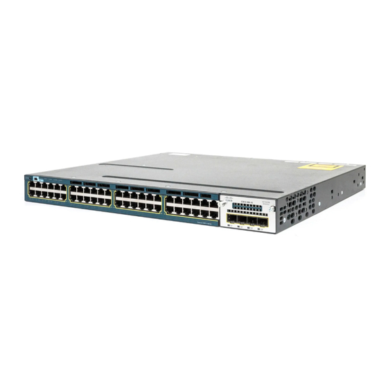
3. You can upgrade to the IP Services feature set when you order the switch. Front Panel Description The switch front panel includes a USB Type B console port, the 10/100/1000 Ethernet ports or the 10/100/1000 PoE+ ports, the network module, and the switch LEDs. -
Page 14: Network Modules
• negotiation, power reservation, and per-port power policing Depending on the installed power supply modules, each port can deliver up to 30 W of PoE+. See Table 1-17 for the power supply matrix that defines the available PoE and PoE+ power per port. -
Page 15: Sfp And Sfp+ Modules
A 10-Gigabit SFP+ module takes precedence over a 1-Gigabit SFP module except when an SFP module is first inserted in Slot 1 and has link. When you insert an SFP+ module in Slot 2, the SFP in Slot 1 retains link. The SFP+ module in Slot 2 does not operate. - Page 16 Chapter 1 Product Overview Front Panel Description Table 1-4 Cisco SFP Modules Supported for the 3750-X and 3560-X Switches Part Number Description GLC-GE-100FX= 100FX SFP on GE SFP ports for LAN switches GLC-LH-SM= GE SFP, LC connector LX/LH transceiver GLC-SX-MM=...
- Page 17 Chapter 1 Product Overview Front Panel Description Table 1-4 Cisco SFP Modules Supported for the 3750-X and 3560-X Switches (continued) Part Number Description DWDM-SFP-4373= DWDM SFP 1543.73-nm SFP (100 GHz ITU grid) DWDM-SFP-4453= DWDM SFP 1544.53-nm SFP (100 GHz ITU grid) DWDM-SFP-4532= DWDM SFP 1545.32-nm SFP (100 GHz ITU grid)
-
Page 18: Leds
The Catalyst 3560-X switch supports the SFP module patch cable (CAB-SFP-50CM), a 0.5-meter, copper, passive cable with SFP module connectors at each end. This cable is only used with 1-Gigabit Ethernet SFP ports to connect two Catalyst 3560-X switches in a cascaded configuration. -
Page 19: Xps Led
(redundancy has been allocated to this device). Port LEDs and Modes Each Ethernet port and 10-Gigabit Ethernet module slot has a port LED. These port LEDs, as a group or individually, display information about the switch and about the individual ports. The port mode determines the type of information shown by the port LEDs. - Page 20 When you press the Mode button on any switch in the Catalyst 3750-X switch stack, all the stack switches change to show the same selected mode. For example, if you press the Mode button on the stack master to show the SPEED LED, all the other switches in the stack also show the SPEED LED.
-
Page 21: Usb Console Led
PoE+ is denied because providing power to the powered device will green and exceed the switch power capacity. amber Blinking amber PoE+ is off due to a fault or because it has exceeded a limit set in the switch software. PoE+ faults are caused when noncompliant cabling or Caution powered devices are connected to a PoE+ port. -
Page 22: S-Pwr Led (Catalyst 3750-X)
LEDs on the first switch, which is stack member number 1. For example, if you press the Mode button and select Stack, the LED for port 1 blinks green. The LEDs for ports 2 and 3 are solid green, as these represent the member numbers of other switches in the stack. -
Page 23: Poe+ Led
Stack LEDs are amber when the ports are down. PoE+ LED If the PoE+ LED mode is not selected on a switch with PoE+ ports, the PoE+ LED still shows detected PoE+ problems. Table 1-13... -
Page 24: Network Module Leds
Link is on, no activity. Blinking green Activity on a link, no faults. Blinking amber Link is off due to a fault or because it has exceeded a limit set in the switch software. Link faults are caused when noncompliant cabling is Caution connected to an SFP or SFP+ port. -
Page 25: Rear Panel Description
Rear Panel Description Rear Panel Description The switch rear panel has a ground connector, an RJ-45 console port, an RJ-45 10/100 management port, a USB Type A connector, two StackWise connectors (only Catalyst 3750-X switches), two fan modules, an XPS-2200 connector, a StackPower connector (only Catalyst 3750-X switches), and two power supply module slots. -
Page 26: Rj-45 Console Port Led
The interface supports Cisco USB flash drives with capacities from 64 MB to 1 GB. Cisco IOS software provides standard file system access to the flash device: read, write, erase, and copy, as well as formatting of the flash device with a FAT file system. You can boot the switch from a USB drive. -
Page 27: Power Supply Modules
Switch Power Supply Modules The switch has two internal power supply module slots. You can use two AC modules, two DC modules, a mixed configuration of one AC and one DC power supply module, or one power supply module and a blank module. - Page 28 Blank module Blank module Blank module 1. For full 15.4 W support on a 48-port PoE+ switch, you must use a C3KX-PWR-1100WAC power supply module. 2. This module is used only in Japan. Table 1-17 Switch Power Supply Requirements for PoE and PoE+...
-
Page 29: Fan Modules
When the fan modules are operating properly, a green LED is on at the top left corner of the fan assembly (viewed from the rear). If the fan fails, the LED turns to amber. -
Page 30: Stackpower Connector (Catalyst 3750-X Switches)
StackPower Stack (Catalyst 3750-X Switches)” section on page 2-8. Management Ports Ethernet Management Port You can connect the switch to a host such as a Windows workstation or a terminal server through the 10/100 Ethernet management port or one of the console ports (see Figure 1-5 Figure 1-6). -
Page 31: Usb Mini-Type B Port
USB connector taking precedence over the RJ-45 connector. Use a USB type-A-to-USB 5-pin mini-Type B cable to connect a PC or other device to the switch. The required USB cable is included in the optional accessory kit, (part number 800-33434). -
Page 32: Network Configurations
Cisco IOS CLI • You can configure and monitor the switch and switch cluster members from the CLI. You can access the CLI by connecting your management station directly to the switch console port or by using Telnet from a remote management station. See the switch command reference on Cisco.com for more information. -
Page 33: Chapter 2 Switch Installation
C H A P T E R Switch Installation This chapter describes how to install and connect a Catalyst 3750-X or a 3560-X switch. It also includes planning and cabling considerations for stacking switches (only Catalyst 3750-X switches). Read the... - Page 34 Metal objects will heat up when connected to power and ground and can cause serious burns or weld the metal object to the terminals. Statement 43 Do not stack the chassis on any other equipment. If the chassis falls, it can cause severe bodily injury Warning and equipment damage.
-
Page 35: Installation Guidelines
Caution To comply with the Telcordia GR-1089 NEBS standard, PoE or non-PoE 10/100/1000 Ethernet port cables that exit from either the left or right side of the switch should be routed and tied to the nearest rack metal. The grounding architecture of this product is DC-isolated (DC-I) -
Page 36: Tools And Equipment
Airflow around the switch and through the vents is unrestricted. • Temperature around the unit does not exceed 113°F (45°C). If the switch is installed in a closed or • multirack assembly, the temperature around it might be greater than normal room temperature. -
Page 37: Switch Data Stacking Guidelines
If you do not specify the length of the StackWise cable, the 0.5-meter cable is supplied. If you need the 1-meter cable or the 3-meter cable, you can order it from your Cisco supplier. For cable part numbers, see the “StackWise Ports”... - Page 38 Chapter 2 Switch Installation Data Stack Cabling Configurations Figure 2-1 Data Stacking the Switches in a Rack or on a Table Using the 0.5-meter StackWise Cable STACK 1 STACK 2 STACK 1 STACK 2 STACK 1 STACK 2 STACK 1...
-
Page 39: Data Stack Bandwidth And Partitioning Examples
Figure 2-7 show data stacks of Catalyst 3750-X switches with failover conditions. In Figure 2-6, the StackWise cable is bad in link 2. Therefore, this stack provides only half bandwidth and does not have redundant connections. In Figure 2-7, link 2 is bad. Therefore, this stack partitions into two stacks, and the top and bottom switches become stack masters. -
Page 40: Power On Sequence For Switch Data Stacks
After 1 minute, power on the other switches in the stack. If you have no preference as to which switch becomes the stack master, power on all the switches in •... -
Page 41: Stackpower Cabling Configurations
Length of cable. Depending on the configurations that you have, you might need different-sized • cables. If you do not specify the length of the StackPower cable, the 0.3 meter cable is supplied. If you need the 1.5 meter cable, you can order it from your Cisco supplier. For cable part numbers, see “StackPower Connector (Catalyst 3750-X Switches)”... - Page 42 Length CAB-SPWR-30CM Catalyst 3750-X StackPower cable 0.3 meter CAB-SPWR-150CM Catalyst 3750-X StackPower cable 1.5 meter Figure 2-8 StackPower Cable for Use Only with Catalyst 3750-X Switches Table 2-2 XPS-2200 Cables Part Number Cable Type Length CAB-XPS-58CM XPS-2200 connector cable 0.58 meter...
- Page 43 You can configure a ring power stack or use the XPS-2200 to configure a star topology. Figure 2-10 shows a ring configuration using both of the supplied 0.3-meter StackPower cables and one 1.5-meter cable. In these examples, the switches are stacked in a vertical rack or on a table. Figure 2-10 StackPower Ring Topology...
- Page 44 A power stack can include a maximum of four switches. You can configure multiple power stacks within a data stack, but a power stack that spans multiple data stacks is not supported.
- Page 45 S TA C K Figure 2-13 Figure 2-14 are examples of recommended configurations when the switches are mounted side-by-side. Use the 1.5-meter StackPower cables to connect the switches. These configurations provide redundant connections. Figure 2-13 PowerStack: Four Switches in a Side-by-Side Mounting Configuration...
-
Page 46: Stackpower Partitioning Examples
• After Installing the Switch, page 2-21 • The illustrations shown in this section show the Catalyst 3750-X-48 PoE switch as an example. You can install the Catalyst 3750-X and 3560-X switches following the same procedures. Rack-Mounting To install the switch in a 19-inch rack, follow the instructions described in this section. - Page 47 This unit should be mounted at the bottom of the rack if it is the only unit in the rack. • When mounting this unit in a partially filled rack, load the rack from the bottom to the top with the heaviest component at the bottom of the rack.
- Page 48 19-inch brackets, part number 700-29656-01 23-inch brackets, part number 700-31900-01 23/24-inch brackets, part number 700-31901-01 ETSI brackets, part number 700-31899-01 Extension rails and brackets for four-point mounting, kit part number 53-3408-01 Catalyst 3750-X and 3560-X Switch Hardware Installation Guide 2-16 OL-19593-01...
-
Page 49: Attaching The Rack-Mount Brackets
Switch Installation Installing the Switch Attaching the Rack-Mount Brackets To install the switch in a rack, use four Phillips flat-head screws to attach the long side of the brackets to the switch for the front- or rear-mounting positions (Figure 2-18). Use three screws to attach the brackets for the mid-mounting position. -
Page 50: Mounting The Switch In A Rack
Four-point mounting positions Mid-mounting position Mounting the Switch in a Rack After the brackets are attached to the switch, use the supplied Phillips machine screws to attach the brackets to the rack (Figure 2-19). Use the black Phillips machine screw to attach the cable guide to the left or right bracket. - Page 51 375 0-X PoE +48 G2 /TE 1 G4 /TE 2 Phillips machine screw, black Mid-mounting position Cable guide Rear-mounting position Front-mounting position Four-point mounting position Number-12 or number-10 Phillips machine screws Catalyst 3750-X and 3560-X Switch Hardware Installation Guide 2-19 OL-19593-01...
-
Page 52: Table- Or Shelf-Mounting
Table- or Shelf-Mounting To install the switch on a table or shelf, locate the adhesive strip with the rubber feet in the mounting-kit envelope. Attach the four rubber feet to the recessed areas on the bottom of the chassis (See Figure 2-20). -
Page 53: After Installing The Switch
2-22). Using a ratcheting torque screwdriver, tighten the retainer screws to 5 lbf-in. (80 ozf-in.). Step 3 Connect the other end of the cable to the connector on the other switch, and tighten the retainer screws to 5 lbf-in. (80 ozf-in.). Avoid overtightening the screws. Figure 2-22... -
Page 54: Connecting To The Stackpower Ports (Catalyst 3750-X Switches)
Remove the dust covers from the StackPower cable connectors. Step 1 Connect the end of the cable with a green stripe to either StackPower connector on the first switch. Align Step 2 the connector correctly, and connect the cable to a StackPower port on the switch rear panel. -
Page 55: Connecting The Stackpower Ports To The Xps-2200
To prevent misconfiguration, the StackPower ports on the switch and the XPS-2200 are keyed and have colored stripes that match the keying and stripes on the StackPower cable ends. Connect the end of the cable with a green stripe to the connector marked XPS on the switch. Align the Step 1 connector correctly, and insert the end of the cable with a green stripe into an XPS port on the switch rear panel. -
Page 56: Tools And Equipment
Installing Network Modules When installing network modules, observe these general precautions: Do not remove the EMC plug from the 10-Gigabit Ethernet slot until you are ready to install an SFP • or SFP+ module. Either a module or a dust plug must be installed in the slot at all times. -
Page 57: Removing A Network Module
Loosen the captive screws that hold the network module in place. Step 5 Carefully press the tab on the right side of the network module to release it from the slot. Grasp the edges of the module, and carefully slide it out of the slot. -
Page 58: Installing An Sfp Module
If the SFP module has a bale-clasp latch, move it to the open, unlocked position. Step 3 Align the module in front of the slot opening, and push until you feel the connector snap into place. Step 4 Figure 2-26... -
Page 59: Removing An Sfp Module
Insert a dust plug into the optical ports of the SFP module to keep the optical interfaces clean. Step 3 If the module has a bale-clasp latch, pull the bale out and down to eject the module. If the bale-clasp Step 4 latch is obstructed and you cannot use your finger to open it, use a small, flat-blade screwdriver or other long, narrow instrument to open the bale-clasp latch. -
Page 60: 10/100/1000 Ethernet Port Connections
PoE inline power supports devices compliant with the IEEE 802.3af standard, as well as prestandard Cisco IP Phones and Cisco Aironet Access Points. Each port can deliver up to 15.4 W of PoE. PoE+ inline power supports devices compliant with the IEEE 802.3at standard, by delivering up to 30 W of PoE+ power per port to all switch ports. -
Page 61: Where To Go Next
Enter the number and types of powered devices that you plan to attach to the switch, and the calculator shows the PoE or PoE+ power required and the system power consumption. You must be a registered Cisco.com user to access the Cisco Power Calculator. If you do not have a user ID or password, you can register: http://tools.cisco.com/RPF/register/register.do... - Page 62 Switch Installation Where to Go Next Use the CLI to configure the switch as a member of a cluster or as an individual switch from the • console. See the switch command reference on Cisco.com for information on using the CLI with the switch.
-
Page 63: Power Supply Module Overview
XPS-2200. A Catalyst 3750-X switch that is part of a StackPower stack operates with power supplied by other stack switches. You can use two AC modules, two DC modules, one AC and one DC module, or one module and a blank cover. -
Page 64: C H A P T E R 3 Power Supply And Fan Module Installation
115 and 240 VAC. The 440-W DC power supply module has dual input feeds (A and B) and supports input voltages between 36 and 72 VDC. The output voltage range is 51 to 57 V. Catalyst 3750-X and 3560-X Switch Hardware Installation Guide... - Page 65 Power Supply Module Overview Each AC power supply module has a power cord for connection to an AC power outlet. The 1100-W and 715-W modules use a 16-AWG cord (only North America). All other modules use an 18-AWG cord. The DC power supply module must be wired to a DC power source.
- Page 66 Input power terminals (positive polarity) Terminal block safety cover Input power terminals (negative polarity) If no power supply is installed in a power supply slot, install a power supply slot cover (Figure 3-5). Catalyst 3750-X and 3560-X Switch Hardware Installation Guide...
-
Page 67: Installation Guidelines
Observe these guidelines when removing or installing a power supply or fan module: Do not force the power supply or fan module into the slot. This can damage the pins on the switch •... -
Page 68: Installing An Ac Power Supply
When replacing the 1100-W or 715-W power supply, verify that you are using the correct power cord • (CAB-16AWG-AC, only in North America). Do not reach into a vacant slot or chassis while you install or remove a module or a fan. Exposed Warning circuitry could constitute an energy hazard. Statement 206 Only trained and qualified personnel should be allowed to install, replace, or service this equipment. -
Page 69: Installing A Dc Power Supply
A C O K Step 7 Connect the power cord to the power supply and to an AC power outlet. Turn on the power at the power source. Confirm that the power supply AC OK and PS OK LEDs are green. See... -
Page 70: Equipment That You Need
DC circuit, switch the circuit breaker to the OFF position, and tape the switch handle of the circuit breaker in the OFF position. Use a voltmeter to test for 0 (zero) voltage at the power terminals on the chassis. Statement 196 This product relies on the building’s installation for short-circuit (overcurrent) protection. -
Page 71: Grounding The Switch
Follow the grounding procedure instructions, and use a UL-listed lug (included in the accessory kit). Caution Follow these steps to install either a single-ground lug or a dual-ground lug on the switch. Make sure to follow any grounding requirements at your site. -
Page 72: Installing The Dc Power Supply In The Switch
Step 6 Using a ratcheting torque screwdriver, torque the ground-lug screws to 60 lbf-in. (960 ozf-in.). Connect the other end of the grounding wire to an appropriate grounding point at your site or to the rack. Step 7 Figure 3-10... -
Page 73: Wiring The Dc Input Power Source
(negative to negative, positive to positive) when connecting the wires to the terminal blocks. Connect the ground wire to a grounded metal rack or to earth ground if the switch is not in a grounded rack. -
Page 74: Finding The Power Supply Module Serial Number
Step 7 the module LEDs. Finding the Power Supply Module Serial Number If you contact Cisco Technical Assistance regarding a power supply module, you need to know the serial number. See Figure 3-14 Figure 3-16 to find the serial number. - Page 75 Chapter 3 Power Supply and Fan Module Installation Finding the Power Supply Module Serial Number Figure 3-15 715-W and 350-W AC Power Supply Module Serial Number SN: XXXNNNNXXXX C 3 K X -P -7 1 5 Catalyst 3750-X and 3560-X Switch Hardware Installation Guide...
-
Page 76: Fan Module Overview
C 3 K X -P -4 4 0 Fan Module Overview The switch has two fan modules. Each fan module contains two fans. Fan modules are hot-swappable. Figure 3-17 Fan Module Catalyst 3750-X and 3560-X Switch Hardware Installation Guide 3-14... -
Page 77: Installing A Fan Module
(Figure 3-18). When correctly inserted, the fan module is flush with the switch rear panel. When the fan is operating, a green LED is on in the top left corner of the fan. Do not reach into a vacant slot or chassis while you install or remove a module or a fan. Exposed Warning circuitry could constitute an energy hazard. - Page 78 Chapter 3 Power Supply and Fan Module Installation Finding the Fan Module Serial Number Figure 3-19 Fan Module Serial Number SN: XXXNNNNXXXX Catalyst 3750-X and 3560-X Switch Hardware Installation Guide 3-16 OL-19593-01...
-
Page 79: Chapter 4 Troubleshooting
When POST completes successfully, the System LED remains green. The XPS LED is green for some time and then returns to its operating status. The other LEDs turn off and return to their operating status. If the switch fails POST, the System and Ethernet management port LEDs turn amber. -
Page 80: Switch Connections
Link Status Verify that both sides have link. A broken wire or a shut down port can cause one side to show link even though the other side does not have link. A port LED that is on does not guarantee that the cable is functional. It might have encountered physical stress, causing it to function at a marginal level. -
Page 81: 10/100/1000 Port Connections
Noncompliant cabling or powered devices can cause a PoE port fault. Use only compliant cabling to Caution connect Cisco prestandard IP phones, wireless access points, or IEEE 802.3af-compliant devices. The output of the PoE circuit has been evaluated as a limited power source (LPS) per IEC 60950. Note SFP Modules Use only Cisco network modules and SFP modules. -
Page 82: Interface Settings
Interface Settings Verify that the port or interface is not disabled or powered off. If a port or interface is manually shut down on either side of the link, it does not come up until you re-enable the interface. Use the show interfaces privileged EXEC command to see if the interface is error-disabled, disabled, or shut down on either side of the connection. -
Page 83: Autonegotiation And Network Interface Cards
Resetting the Switch to the Factory Default Settings If you have configured a new switch with a wrong IP address, or if all of the switch LEDs start blinking when you try to enter Express Setup mode, you can clear the IP address that is configured on the switch. -
Page 84: Finding The Switch Serial Number
To replace a failed data stack member: The replacement switch must be a Catalyst 3750-X switch. Power down the failed switch. Remove AC or DC input power, and if the switch is part of a StackPower stack, remove the StackPower cables. -
Page 85: Appendix
Relative humidity 10 to 85% (noncondensing) Operating altitude Up to 10,000 ft (3049 m) Storage altitude Up to 15,000 ft (4573 m), NEBS up to 13,000 ft (4000 m) Physical Specifications Catalyst 3750-X and 3560-X Switch Hardware Installation Guide OL-19593-01... -
Page 86: Power Supply Module Specifications
16.6 lb (7.5 kg) Dimensions (H x W x D) Catalyst 3750-X and 3560-X-24T 1.75 x 17.5 x 18.0 in. (4.45 x 44.5 x 46.0 cm) Catalyst 3750-X and 3560-X-24P 1.75 x 17.5 x 18.0 in. (4.45 x 44.5 x 46.0 cm) Catalyst 3750-X and 3560-X-48T 1.75 x 17.5 x 18.0 in. -
Page 87: Appendix A Technical Specification
C3KX-PWR-350WAC: 1194 Btus per hour, 350 W 1. The total input and total output BTU ratings refer to input power to the power supply and output power to the switch. The BTU ratings are based on 100 VAC for the 350-W and 715-W power supplies and 115 VAC for the 1100-W power supply. -
Page 88: Fan Module Specifications
Branch circuit protection C3KX-PWR-440WDC: 20 A 1. The total input and total output BTU ratings refer to input power to the power supply and output power to the switch. The BTU ratings are based on –36 VDC. Fan Module Specifications... - Page 89 VCCI Class A AS/NZS CISPR22 Class A China EMC certifications GOST Environmental Reduction of Hazardous Substances (ROHS) 5 Noise specifications Office product spec: 48 dBA at 86º F (30º C) Telco CLEI code Catalyst 3750-X and 3560-X Switch Hardware Installation Guide OL-19593-01...
- Page 90 Appendix A Technical Specifications Fan Module Specifications Catalyst 3750-X and 3560-X Switch Hardware Installation Guide OL-19593-01...
-
Page 91: Appendix
• 10/100 Ethernet Management Port, page B-3 • Console Port, page B-4 • 10/100/1000 Ports The 10/100/1000 Ethernet ports on switches use RJ-45 connectors and Ethernet pinouts. Figure B-1 10/100/1000 Port Pinouts Label 4 5 6 7 8 TP0+ TP0-... -
Page 92: Gigabit Ethernet Cx1 (Sfp+ Copper) Connectors
Appendix B Connector and Cable Specifications Connector Specifications 10 Gigabit Ethernet CX1 (SFP+ Copper) Connectors The 10-Gigabit Ethernet electrical modules use CX1 copper connectors similar to the one shown in Figure B-2. Note When ordering or using CX1 cables, ensure that the version identifier is 2 or higher. -
Page 93: A P P E N D I X B Connector And Cable Specifications
TP3+ TP3- Figure B-6 SFP Module Patch Cable (Catalyst 3560-X Switches) 10/100 Ethernet Management Port The 10/100 Ethernet management port uses RJ-45 connectors with Ethernet pinouts. Figure B-7 shows the pinouts. Catalyst 3750-X and 3560-X Switch Hardware Installation Guide OL-19593-01... -
Page 94: Console Port
10/100 Port Pinouts Label 4 5 6 7 8 Console Port The switch has two console ports: a USB 5-pin mini-Type B port on the front panel (see Figure B-8) and an RJ-45 console port on the rear panel. Figure B-8... -
Page 95: Cable And Adapter Specifications
B-3.) The supplied RJ-45-to-DB-9 adapter cable is used to connect the console port of the switch to a console PC. You need to provide a RJ-45-to-DB-25 female DTE adapter if you want to connect the switch console port to a terminal. - Page 96 2. A mode-field diameter/cladding diameter = 9 micrometers/125 micrometers. 3. A mode-conditioning patch cord is required. Using an ordinary patch cord with MMF or 1000BASE-LX/LH SFP modules and a short link distance can cause transceiver saturation and an elevated bit error rate (BER). When using the LX/LH SFP module with 62.5-micron diameter MMF, you must also install a mode-conditioning patch cord between the SFP module and the MMF cable on both the sending and receiving ends of the link.
-
Page 97: Four Twisted-Pair Cable Pinouts
Two Twisted-Pair Cable Pinouts Figure B-12 Two Twisted-Pair Straight-Through Cable Schematic Switch Router or PC 3 TD+ 3 RD+ 6 TD– 6 RD– 1 RD+ 1 TD+ 2 RD– 2 TD– Catalyst 3750-X and 3560-X Switch Hardware Installation Guide OL-19593-01... -
Page 98: Identifying A Crossover Cable
To identify a crossover cable, hold the cable ends side-by-side, with the tab at the back. The wire connected to the pin on the outside of the left plug should be the same color as the wire connected to the pin on the outside of the right plug. - Page 99 RJ-45-to-DB-25 female DTE adapter, and the console device. The RJ-45-to-DB-25 female DTE adapter is not supplied with the switch. You can order a kit with the Note adapter (part number ACS-DSBUASYN=) from Cisco.
- Page 100 Appendix B Connector and Cable Specifications Cable and Adapter Specifications Catalyst 3750-X and 3560-X Switch Hardware Installation Guide B-10 OL-19593-01...
-
Page 101: Appendix
This appendix provides a CLI-based setup procedure for a Catalyst 3750-X and 3560-X standalone switch or a switch stack. To set up the switch by using Express Setup, see the Cisco 3750-X and 3560-X Switch Getting Started Guide. Before connecting the switch to a power source, review the safety warnings in Chapter 2, “Switch Installation.”... -
Page 102: A P P E N D I X C Configuring The Switch With The Cli-Based Setup Program
RJ-45 Console Port The RJ-45 console port is on the rear panel of the switch. Connect the RJ-45-to-DB-9 adapter cable to the 9-pin serial port on the PC. Connect the other end of the Step 1 cable to the switch console port. -
Page 103: Installing The Cisco Microsoft Windows Usb Device Driver
S T A C K P o E 1 1 1 2 Connect a USB cable to the PC USB port. Connect the other end of the cable to the switch mini-B Step 2 (5-pin-connector) USB console port. See Figure C-1. -
Page 104: Installing The Cisco Microsoft Windows Xp Usb Driver
The InstallShield Wizard Completed window appears. Click Finish. Step 5 Connect the USB cable to the PC and the switch console port. The USB console port LED turns green, Step 6 and the Found New Hardware Wizard appears. Follow the instructions to complete the driver installation. -
Page 105: Uninstalling The Cisco Microsoft Windows Usb Driver
The InstallShield Wizard Completed window appears. Click Finish. Step 5 Connect the USB cable to the PC and the switch console port. The USB console port LED turns green, Step 6 and the Found New Hardware Wizard appears. Follow the instructions to complete the driver installation. -
Page 106: Uninstalling The Cisco Microsoft Windows Vista And Windows 7 Usb Driver
Step 5 Entering the Initial Configuration Information To set up the switch, you need to complete the setup program, which runs automatically after the switch is powered on. You must assign an IP address and other configuration information necessary for the switch to communicate with the local routers and the Internet. - Page 107 On a command switch, the host name is limited to 28 characters and on a member switch to 31 characters. Do not use -n, where n is a number, as the last character in a host name for any switch.
- Page 108 [1] Return back to the setup without saving this config. [2] Save this configuration to nvram and exit. If you want to save the configuration and use it the next time the switch reboots, select option 2 to save it in nonvolatile RAM (NVRAM).
- Page 109 See CLI connection procedures 2-23 to 2-29 connectors and cables B-1 to B-9 bodily injury protection warning 2-15 console port brackets connectors and cables See mounting brackets described 1-20 Catalyst 3750-X and 3560-X Switch Hardware Installation Guide IN-1 OL-19593-01...
- Page 110 SFP and SFP+ modules 2-25 to 2-27 for initial switch configuration 2-21 site requirements using to clear switch IP address starting the terminal emulation software table or shelf-mounting 2-20 See also procedures Catalyst 3750-X and 3560-X Switch Hardware Installation Guide IN-2 OL-19593-01...
- Page 111 2-20 two twisted-pair mounting brackets PoE+ rack-mount faults caution 2-18 1-11 table- or shelf-mounting 2-20 1-10, 1-13 port connections 2-28 ports described power planning tool 2-28 shock hazard warning 2-29 Catalyst 3750-X and 3560-X Switch Hardware Installation Guide IN-3 OL-19593-01...
- Page 112 1-20 described StackWise ports 1-15 to 1-16 1-16 Ethernet management port 1-20 straight-through cable pinout fan module four twisted-pair 1-19 power-supply module two twisted-pair 1-17 Catalyst 3750-X and 3560-X Switch Hardware Installation Guide IN-4 OL-19593-01...
- Page 113 PoE+ connections port and interface settings POST serial number location spanning tree loops connector 1-19 speed, duplex, and autonegotiation described 1-19 transceivers with LEDs troubleshooting spanning tree loops Catalyst 3750-X and 3560-X Switch Hardware Installation Guide IN-5 OL-19593-01...
- Page 114 Index Catalyst 3750-X and 3560-X Switch Hardware Installation Guide IN-6 OL-19593-01...
Need help?
Do you have a question about the Catalyst 3560X-24T and is the answer not in the manual?
Questions and answers