
Subscribe to Our Youtube Channel
Related Manuals for Weco H-ESY Series


Summary of Contents for Weco H-ESY Series
- Page 1 H-ESY SERIES H-ESY Serials Hybrid Inverter User Manual Suitable for the European market 400Vac...
-
Page 2: Symbolic Conventions
Preface Overview This document mainly introduces the installation, electrical connection, commissioning, maintenance and fault-handling methods of H-ESY inverter. Please read this manual carefully before installation and use to understand the safety information and familiarize yourself with the functions and features of H-ESY inverter. All the manual details, installation instructions, operation, maintenance and troubleshooting are intended to be for qualified electricians and expert installers This inverter can be used after proper training. -
Page 3: Surge Protection
Label Meaning This label indicates there is high voltage within the product, and touch may cause an electric shock. This symbol indicates that the temperature here is high, do not touch in order to avoid personal injury. This symbol indicates here is the protective grounding (PE) terminal, and solid grounding is needed to ensure operators’... -
Page 4: Table Of Contents
Table of Contents 1 Safety Instructions ................................6 2 Product Introduction ................................ 9 2.1 Product Introduction ................................9 2.2 Description of appearance ..............................10 2.3 Terminals of inverter................................11 2.4 Technical Parameters ................................12 2.5 Label Description ..................................13 2.6 How it works ................................... 15 3 Storage .................................... - Page 5 9 Inverter Disposal ................................54 9.1 Disassemble the inverter ................................ 54 9.2 Packaging inverters ................................54 9.3 Scrap inverters ..................................54 Appendix A Grid Standard Code............................55 Appendix B abbreviations ..............................56...
-
Page 6: Safety Instructions
All operation of this equipment must strictly comply with the relevant equipment precautions and special safety instructions provided by WECO. The safety warnings listed in the manual represent only those known to WECO and WECO assumes no responsibility for violations of general safe operating requirements or safety standards for the design, production and use of the equipment. -
Page 7: System Installation
System installation Danger! It is strictly forbidden to operate the H-ESY inverter with electricity during installation ⚫ The process of lifting or placing the inverter must be carried out slowly and cannot be placed quickly, otherwise the product may be damaged. ⚫... -
Page 8: Maintenance And Replacement
Maintenance and replacement Danger! During the operation of the H-ESY inverter, there is a high voltage that can cause electric shock, resulting in death, serious personal injury, or serious property damage. Therefore, before carrying out any maintenance work, it is necessary to turn off the power supply of the H-ESY inverter and operate it in strict accordance with the safety precautions listed in this manual and other relevant document. -
Page 9: Product Introduction
2 Product Introduction 2.1 Product Introduction Function H-ESY inverter can convert solar energy into alternating current or can store DC energy into the Energy Storage Battery, the user can flexibly choose the appropriate working mode according to the actual situation of photovoltaic, power grid, battery, load and so on via APP. -
Page 10: Description Of Appearance
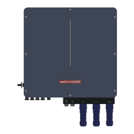
PV11+ PV11- PV12+ LOAD PV12- PV21+ PV21- PV22+ PV22- GRID BAT+ BAT- BMS-CAN Please pay attention to CT installation. CT with yellow wire must be installed on L1, green on L2 and red on L3. 2.2 Description of appearance SIDE FRONT BACK... -
Page 11: Terminals Of Inverter
2.3 Terminals of inverter D E F G H PV input BATTERY input Type-c upgrade interface COM (WIFI BMS, DRM, CAN, CT Grid Generator BACK-UP PV DC switch LED Bar Signal Connection Port Function Name description UPDATE Local monitoring and upgrading ports. WIFI interface. -
Page 12: Technical Parameters
Battery Working Voltage Range [V] 150V ~ 550 V Max. Charging/Discharging Current [A] Rated Charging/Discharging current [A] Battery Type Li-Ion Communication Interface WeCo-CAN EPS output Rated Output Power [kVA] Max. Apparent Power (kVA) 13.2 16.5 Rated Output Current [A] 11.5 14.4... -
Page 13: Label Description
Ingress Protection IP65 Noise Emission [dB] ≤25 Operating Temperature [°C] -25 ~ 60 Cooling Natural Relative Humidity 0~100% Altitude 4,000m (>2,000m Derating) Dimensions W *D *H [mm] 572*220*670(Including terminals) Weight [kg] Isolation Transformer Self-consumption [W] <15 Display LED BAR & APP User interface WiFi Communication with portal... - Page 14 The icon is for reference only, please refer to the actual product. Description of the LEDs. The LED Bar is described in the following table. Equipment status Light language remarks Standby Blink blue light for 6s once (3S lights on,3S lights off) The device is normal, and APP remote shutdown does not work On-Grid Work...
-
Page 15: How It Works
(1) Trademark and product model (2) Important technical parameters (3) Conformity of the certification system logo (4) Company name and origin Read Info The icon is for reference only, please refer to the real object Description of the certification mark icon name meaning... - Page 16 Schematic: Load Breaker BACK-UP PV Breaker Grid Breaker H-ESY INVERTER GRID BAT Breaker Generator Breaker GENERATOR PE BAR NORMAL LOAD Note! • Please control the home loads, and make sure it’s within the “BACK-UP output rating” under BACK-UP mode, otherwise the inverter will shut down with an “overload fault” warning. •...
- Page 17 Working Scenario Brief Description mode Auto Mode Photovoltaic and grid power are available, battery is not available: Photovoltaic is sufficient, priority load use, when there is surplus, feedback to the grid Auto Mode Photovoltaic and grid power are available, battery is not available: Photovoltaic is insufficient for load use, the power grid draws power to meet the load use...
- Page 18 Working Scenario Brief Description mode Plan Mode Battery and grid power are available, PV is not available: During the charging period, the grid draws power to meet the load and battery charging use Plan Mode Battery and grid power are available, PV is not available: During the discharge period, the battery discharge meets the load use, and when there is surplus, it feeds back to the grid Bat Priority...
-
Page 19: Storage
3 Storage If the inverter is not immediately put into service within 2 months from the production date, the storage specifications need to be met as follow: ⚫ Do not remove the outer packaging of the inverter. ⚫ The storage temperature should be kept at –20°C~+60°C; The relative humidity should be maintained at 5% RH~95% ⚫... -
Page 20: Installation
4 Installation 4.1 Pre-installation inspection Check the outer packaging Before unpacking the inverter, check the outer packaging for visible damage, such as holes, cracks, or other signs of possible damage inside, and check the inverter model. If there is any abnormal packaging or inverter model does not match, do not open it and contact your dealer as soon as possible Note!... -
Page 21: Select The Installation Location
Crimping pliers (Model: Open Wrench (Model: H4TC0001; Manufacturer: H4TW0001; Manufacturer: Amphenol). Amphenol). Markers Multimeter (DC voltage range vacuum cleaner ≥ 600V DC). Hydraulic pliers Horizontal ruler Steel tape measure Hexagon wrench set Heat shrink tubing Heat guns Personal protective equipment Protective goggles Dust masks Safety gloves... -
Page 22: Installation Requirements
Installation requirements ⚫ The inverter mounting must have fire resistance according with the local rules (please refer to the safety officer of your company for more details). ⚫ Do not install the inverter nearby flammable materials, liquid or gas, the installation site must be approved by the local authorities. - Page 23 Step 2. Use the 5 M6*16 screws to fix the crossbar on the back of the inverter as shown in the figure below. Step 3. Lift the inverter, hang the hook on the inverter onto the mounting bracket.
- Page 24 Step 4. Fix both sides of the inverter with hexagonal 4 M6*16 screws. Due to distance limitations, it is recommended to use hexagonal M6 * 16 screws.
-
Page 25: Electrical Connections
Photovoltaic strings consist of photovoltaic Not provided by modules connected in series. The H-ESY WeCo inverter supports 2 string inputs. Energy storage H-ESY inverter supports WECO energy Can be provided equipment storage device access. separately Generator H-ESY inverter supports grid access. -
Page 26: Back-Up: Load Connection
5.2 Back-up: Load Connection The H-ESY hybrid inverters have on-grid and grid-off functions. When the grid is on, the inverter can export power through the AC port, while when the grid is off, it will export power through the BACKUP ports. Auto &... -
Page 27: Grid Connection And Generator Connection
LOAD 5.3 Grid Connection and Generator Connection Prerequisites Before connecting the input line on the AC grid side, please make sure that the other end of the cable is not connected to the grid, or that the AC pre-circuit breaker is in the disconnected state. Detect if the grid voltage is within the allowable range. -
Page 28: Connect The Input Line Of The Energy Storage Device
Step 3: Connect the completed connector to the Grid and Generator interface. GRID 5.4 Connect the input line of the energy storage device Prerequisites Danger! ⚫ Before connecting the input line on the side of the energy storage device, please confirm that the other end of the cable is not connected to the energy storage device, or the energy storage device is not powered on, and its main switch is disconnected. - Page 29 Step 3: Install the communication cable. Communication interface between inverter and battery is CAN with a RJ45 connector. NOTE: For Weco batteries the CAN communication on the battery side is pin 1 and 2 of RJ45. CANL H CAN L...
-
Page 30: Pv Connection
Note! When arranging signal cables, please pay attention to separate the signal cable from the power cable, and avoid large interference sources when routing, so as to avoid signal interference and affect communication. Step a: Production of communication cables. One end of the communication line is connected to the crystal head of the network cable. The wire sequence is shown in the figure above. -
Page 31: Wifi Connection
Step1. Plug WiFi into “COM” port at the bottom of the inverter. Step2. Set the connection between the inverter and router following the instruction of the WeCo NooR APP. Step3. Create a user account online. (Please check the WiFi user manual for more details). -
Page 32: Ct (Current Transform)
5.7 CT (current transform) CT is abbreviation for “current transform”, is used to detect Grid current. The RJ45 connector of CT is connected to CT interface of inverter. The CT is connected to the three-phase L1, L2 L3 of grid power. The CTs of the three-phase inverter are connected to different colored communication lines. -
Page 33: System Debugging
6 System debugging 6.1 Check before powering on Inspection items and acceptance criteria serial number Check the item Acceptance criteria The inverter is installed in place The inverter is installed correctly and is robust and reliable. The WiFi antenna is in place WiFi antennas are installed correctly and are robust and reliable. -
Page 34: Power Down The System
6.3 Power down the system Warning! ⚫ After the inverter is powered down, there is still residual power and heat in the chassis, which may cause electric shock or burns. Therefore, after 5 minutes of powering down the inverter system, wear protective gloves before operating the inverter. -
Page 35: Noor Cloud App Operation
7 Noor Cloud APP Operation 7.1 App Introduction Function Noor Cloud App (abbreviated as app) is a cloud through 2.4G network and a wifi module. The mobile application software of terminal communication can realize alarm query, parameter configuration, daily maintenance, debugging and other functions, and is a convenient maintenance platform. Connection method After the DC side or AC side of the inverter is powered on, it can be connected to the APP through wifi module and external router:... -
Page 36: Login And Logout Of The App
7.4 Login and Logout of the APP 7.4.1 Login APP After correctly installing the app on your mobile phone, you can use it by logging into the app. Steps: On the mobile desktop, use the Noor App application icon to login. On the app login page, enter your account and password, then click "Sign in". -
Page 37: Build A Power Station Wizard
7.5 Build a Power Station Wizard Precondition After completing the device commissioning, you can use Noor App to create a power station and configure the basic information, which enables centralized monitoring and management of the devices. 7.5.1 Login at the first time to create an initial power station Step1: After logging in to the Noor App, you can click the "Add plant"... -
Page 38: Add New Device
Step4: After filling in the power station information, use "Save" button to save. 7.6 Add new device After the power station is created, if you want to add new device to the power station, you can add the new device to a power station by this function. Step1: Click the "... -
Page 39: Check The Power Station Status
7.7 Check the power station status The Noor App provides an overview of the power station, real-time status overview of the power station, energy output and consumption, revenue, energy flow diagrams, and other information。 7.7.1 View the details of the power station After logging in to the App, you can view the details of the current power station, or you can click the name on top and select the name of the power station to view the details of the power station. -
Page 40: Device Management
7.7.3 E nergy management On the "Home > Energy" tab, you can view data such as power generation and power consumption of the power station. ⚫ Select time to view the data of that specific day. ⚫ Select Param to view the parameters to compare. 7.8 Device management Users can monitor the status of the device in real time and set parameters. - Page 41 ⚫ Edit device: Click the “ ” icon on the device you want to edit to change the name or config the network. ⚫ 7.8.2 Device parameter setting Step1: Scroll down on the home page and click “inverter settings” to view the setting list. Step2: Click on the "Inverter Setting"...
-
Page 42: Auto Mode
7.8.2.1 Set working mode In the operation mode selection of the basic setting interface, you can set "load priority", "plan mode", and "battery priority" to make the inverter work in different operation modes. Auto mode The priority of photovoltaic power generation is to ensure the load works, and then the remaining photovoltaic power is charged to the energy storage battery. -
Page 43: System Settings
7.8.2.2 System settings Settable functions: Date, Time, EPS enable,PV Input Type, ARC enable, Anti reflux,CT Ratio. Date: Current date. The inverter's statistical function will be performed based on this set date Time: The current time, the system's planning mode, will match this set time EPS Enable: EPS enable switch. -
Page 44: Grid Setting
Off Grid DOD: The lower limit of the discharge SOC during off-grid operation. When it is lower than this value, the battery will no longer discharge. 7.8.2.4 Grid setting Settable functions: Grid Standard, Grid Set, American Standard Classification. Grid Standard: Select the national grid standard, and after confirmation by the state, the voltage amplitude and frequency will be determined. - Page 45 Inv Parallel Num: Number of parallel machines Parallel Master/Slave: Whether the parallel identity is a host or a slave, the slave will work according to the host command. Inv Parallel Addr: Parallel address. In a parallel system, the address cannot be repeated, and can be set between 1-99 Common Battery Enable: Whether the battery is shared in the parallel system.
-
Page 46: Advanced Setting
Generator Start SOC: The generator automatically starts the SOC value. After the battery SOC is lower than this value, if the generator enable is set to enable, the generator start dry connection point will close to start the generator. Generator Stop SOC: The generator automatically stops the SOC value. After the battery SOC is higher than this value, if the generator enable is set to enable, the generator start dry connection point will be disconnected and the generator will be shut down. -
Page 47: Delete Device
Settable functions: AC Power,Bat Discharge Power,Bat Charge Current, Restore Factory Setting,Remote Start UP/ShutDown. Grid Power:Grid connected power dispatching, taking power from the grid and feeding back the maximum power value of the grid, using percentage settings. Bat Discharge Power:Battery discharge power scheduling, maximum power value of battery discharge, usage percentage setting. - Page 48 Step2: Click "Plant Management" to enter. 7.10.2 Edit the basic information of the power station Users can edit the power station name, station address and other information. Step1: Click the " " icon in the upper left corner of the home page, and a page will pop up on the left. Step2: Click "Plant Management"...
-
Page 50: System Maintenance
8 System Maintenance 8.1 Routine Maintenance In order to ensure that the inverter can operate well for a long time, it is recommended to maintain it routinely as described in this section. Caution! Perform system power-down operations while performing maintenance such as system cleaning, electrical connections, grounding reliability, etc. - Page 51 (1) Nothing need to do, Wait one minute for the inverter to restart. Battery discharge over (2) Check whether the load is in compliance with the current. When the battery Dischg Over Cur specification. is loaded, the load is too (3) Cut off...
- Page 52 BUS voltage is over (1) Check the input mode setting is correct. bus over vol maximum value. (2) Restart the inverter and wait until it functions normally. The inverter current Inv over cur exceeds the normal (1) Restart the inverter and wait until it functions normally. value.
- Page 53 (1) Check if the PE line is connected to the inverter and is PV iso low PV iso low connected to the ground. (2) Contact customer service if error warning continues. Bus Relay Fault Grid Relay Fault EPS rly fault Gfci fault The inverter may be (1) Restart the inverter and wait until it functions normally.
-
Page 54: Inverter Disposal
9 Inverter Disposal 9.1 Disassemble the inverter Procedure Step 1 Perform a system power-down operation (see 6.3 System Power-down). Step 2 Disconnect all electrical connections to the inverter, including signal lines, PV input lines, energy storage input lines, AC output lines, and protective ground wires. Step 3 Remove the inverter fixing screws 9.2 Packaging inverters If you also have the original packaging of the inverter, please put it inside the original packaging and seal the... -
Page 55: Appendix A Grid Standard Code
Appendix A Grid Standard Code The list of grid standard codes will be refreshed from time to time, please refer to the actual product. Table A-1 List of grid standard codes serial Grid standard code illustrate Grid voltage Grid frequency number name... -
Page 56: Appendix B Abbreviations
Appendix B abbreviations Alternating Current Direct Current Identifier Light Emitting Diode LVRT Low Voltage Ride-Through Media Access Control MPPT Maximum Power Point Tracking Personal Computer Protective Earthing Photovoltaic Residual Current Device RCMU Residual Current Monitoring Unit Relative Humidity Serial Number THDI Total Harmonic Current Distortion WEEE...
Need help?
Do you have a question about the H-ESY Series and is the answer not in the manual?
Questions and answers