Table of Contents
Advertisement
Advertisement
Table of Contents

Subscribe to Our Youtube Channel
Related Manuals for Weco ESS XTE Series


Summary of Contents for Weco ESS XTE Series
- Page 1 XTE SERIES XTE Hybrid Inverter User Manual -E- Version for European market 230Vac...
- Page 2 Preface Overview This document mainly introduces the installation, electrical connection, commissioning, maintenance, and fault-handling methods of the XTE inverter. Please read this manual carefully before installation and use it to understand the safety information and familiarize yourself with the functions and features of the XTE inverter. All the manual details, installation instructions, operation, maintenance, and troubleshooting are intended to be for qualified electricians and expert installers.
- Page 3 Label Label Description This symbol indicates that the temperature here is higher than the acceptable range of the human body, and do not contact in order to avoid personal injury. This symbol indicates here is the protective grounding (PE) terminal, and solid grounding is needed to ensure operators’...
-
Page 4: Table Of Contents
Table of Contents 1 Safety Instructions ....................................6 2 Product Introduction ....................................9 2.1 Product Introduction ................................. 9 2.2 Description of appearance............................... 10 2.3 Terminals of inverter ................................10 2.4 Technical Parameters ................................11 2.5 Label Description ..................................13 2.6 How it works .................................... 14 3 Storage ......................................... - Page 5 8 System Maintenance.................................... 51 8.1 Routine Maintenance ................................51 8.2 Troubleshooting ..................................51 9 Inverter Disposal ....................................54 9.1 Disassemble the inverter ................................. 54 9.2 Packaging inverters .................................. 54 9.3 Scrap inverters ..................................54 Appendix A Grid Standard Code ................................55 Appendix B abbreviations ..................................
-
Page 6: Safety Instructions
All operations of this equipment must strictly comply with the relevant equipment precautions and special safety instructions provided by WECO. The safety warnings listed in the manual represent only those known to WECO, and WECO assumes no responsibility for violations of general safe operating requirements or safety standards for the design, production, and use of the equipment. - Page 7 System installation Danger! It is strictly forbidden to operate the XTE inverter with electricity during installation. ⚫ The process of lifting or placing the inverter must be carried out slowly and cannot be placed quickly, otherwise the product may be damaged. ⚫...
- Page 8 Maintenance and replacement Danger! During the operation of the XTE inverter, there is a high voltage that can cause electric shock, resulting in death, serious personal injury, or serious property damage. Therefore, before carrying out any maintenance work, it is necessary to turn off the power supply of the XTE inverter and operate it in strict accordance with the safety precautions listed in this manual and other relevant documents.
-
Page 9: Product Introduction
2 Product Introduction 2.1 Product Introduction Function XTE inverter can convert solar energy into alternating current or can store DC energy in the Energy Storage Battery. Through the APP, the user can flexibly choose the appropriate working mode according to the actual situation of photovoltaic, power grid, battery, load, and so on. -
Page 10: Description Of Appearance
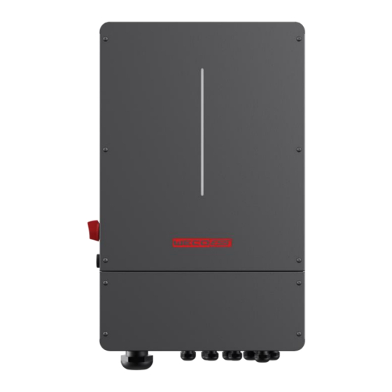
2.2 Description of appearance Front Side Back 2.3 Terminals of inverter PV DC switch BATTERY input Wi-Fi CAN1/CAN2, BMSCAN/CTL1/CTL2/Type-c upgrade PV1 - PV4 input (4 MPPT) Generator Grid Priority Load Ordinary Load LED Bar Start button... -
Page 11: Technical Parameters
Signal Connection * Port Function Port Name Description CAN1 Used to connect the communication interface between inverters for parallel connection CAN2 Used to connect the communication interface between inverters for parallel connection RS485 Read the internal data of the inverter. Internal use, reserved BMS communication for lithium batteries CT-L2 For external grid side CT to detect current size. - Page 12 Max. Charge/Discharge Current [A] 135/135 190/190 210/210 235/235 Battery Type Li-Ion Communication Interface WeCo-CAN EPS output Rated power [kVA] Rated output voltage [V] 230 (single phase not for UL type) Rated output current [A] 33.3 41.6 56.0 Rated frequency [Hz] 50/60 <10...
-
Page 13: Label Description
2.5 Label Description Box identification Symbol Name Meaning Anti-scald warning sign The inverter has a high shell temperature when working, there is a risk of scalding and it is strictly forbidden to touch it Delayed discharge There is a high voltage after the inverter is identification powered on. -
Page 14: How It Works
Nameplate (1) Trademark and product model (2) Important technical parameters (3) Conformity of the certification system logo (4) Company name and origin Read Info The icon is for reference only, please refer to the real object. Description of the certification mark. icon name meaning... - Page 15 Schematic: Note! ⚫ Please control the home loads and make sure it’s within the “BACK-UP output rating” under BACK-UP mode, otherwise the inverter will shut down with an “overload fault” warning. ⚫ Please confirm with the mains grid operator whether there are any special regulations for grid connection. Description of the WORKING MODE Note: when the load is connected in parallel with the AC input line, it is mandatory to install the CT sensor and make sure that the sensor direction is correct.
- Page 16 Working Scenario Brief Description mode Auto Mode Photovoltaic and grid power are available, battery is not available: Photovoltaic is insufficient for load use, the power grid draws power to meet the load use Auto Mode Battery and grid power are available, PV is not available: When the battery is fully charged, the battery is discharged to meet the load use Auto Mode...
- Page 17 Working Scenario Brief Description mode Bat Priority Photovoltaic, grid and battery are available: Solar energy will charge the battery as the priority, if there is a surplus, the excess power will supply the load. If there is still some extra energy, the excess electricity will feed the power to the grid.
-
Page 18: Storage
3 Storage If the inverter is not immediately put into service within 2 months from the production date, the storage specifications need to be met as follows: ⚫ Do not remove the outer packaging of the inverter. ⚫ The storage temperature should be kept at –20°C~+60°C; The relative humidity should be maintained at 5% RH~95% ⚫... -
Page 19: Installation
4 Installation 4.1 Pre-installation inspection Check the outer package. Before unpacking the inverter, check the outer packaging for visible damage, such as holes, cracks, or other signs of possible damage inside, and check the inverter model. If there is any damage or the inverter model does not match, do not open it and contact your dealer as soon as possible. -
Page 20: Select The Installation Location
Tools and gauges Markers Multimeter (DC voltage range vacuum cleaner ≥ 600V DC). Hydraulic pliers Horizontal ruler Steel tape measure Heat shrink tubing Heat guns Personal protective equipment Protective goggles Dust masks Safety gloves Safety boots 4.3 Select the installation location Basic Requirements ⚫... - Page 21 ⚫ Do not install the inverter nearby flammable materials, liquid or gas, the installation site must be approved by the local authorities. ⚫ Please ensure that the installation surface is strong enough to support the inverter and that the support screws can meet the load-bearing requirements of the installed inverter.
-
Page 22: Install The Inverter
4.4Install the inverter Procedure Step 1. Take out the mounting bracket from the accessory, as shown in the figure, and use a drill to make the holes on the wall according to the mounting holes position of the mounting bracket, the hole depth shall be 50- 60mm and the expansion screw shall be selected according with the wall type. -
Page 23: Electrical Connections
Photovoltaic strings Photovoltaic strings consist of photovoltaic Users bring their modules connected in series. The XTE inverter supports 4 string inputs. Energy storage XTE inverter supports WECO energy Users bring their equipment storage device access. Generator XTE inverter supports generator access. -
Page 24: Open The Bottom Wiring Cover
5.2 Open the bottom wiring cover Remove the cover screws by Allen Wrench and remove the cover. 5.3 Back-up: Load1 and Load2 Connection XTE inverter has parallel and off-grid functions, the inverter provides output power through the AC port when connected to the grid and provides output power through the back-up port when off-grid. -
Page 25: Grid Connection And Generator Connection
The XTE inverter can provide an overloaded output via the Backup function. When the battery is not connected, it is strongly not recommended to use the Backup function. Procedure Step 1: Select 8AWG wire, strip off the 18mm long insulation layer, and crimp the round terminal. Step 2: Connect the finished wire through the bottom Backup port to the Backup terminal. -
Page 26: Connect The Input Line Of The Energy Storage Device
5.5 Connect the input line of the energy storage device Prerequisites Danger! ⚫ l Before connecting the input line on the side of the energy storage device, please confirm that the other end of the cable is not connected to the energy storage device or the energy storage device is not powered on, and its main switch is in the disconnected state. - Page 27 INVERTER SIDE Wiring diagram CANL H CAN L BATTERY SIDE Battery SIDE RJ45 Inverter side RJ45 Installation of power cables Procedure Step 1: Make the cable, crimping the OT terminal, using a 25 mm DC cable, stripping the wire, crimping OT 50- 10 Terminals.
- Page 28 (A) Core (B) Insulating layer (C) Heat shrinkable sleeve (D) Hydraulic pliers (E) Heat gun Step 2: Install the power input line of the energy storage device. Use M10 screws to lock the positive and negative poles of the energy storage output with the input end of the inverter battery.
-
Page 29: Pv Connection
5.6 PV Connection Hybrid can be connected in series with 4-string PV modules for 5kW, 6kW, 8kW, and 10kW. Select PV modules with excellent function and reliable quality. The open-circuit voltage of module arrays connected in series should be compatible with the input characteristics of the inverter. Prerequisites Danger! ⚫... -
Page 30: Wifi Connection
Step 1. Plug WiFi into “WiFi” port at the bottom of the inverter. Step 2. Build the connection between the inverter and router following the instruction of the WeCo NooR APP. Step3. Create a user account online (Please check the App section for more details). -
Page 31: System Debugging
6 System debugging 6.1 Check before powering on Inspection items and acceptance criteria Serial Number Item To Check Acceptance Criteria The inverter is installed in place The inverter is installed correctly and is robust and reliable. The WiFi antenna is in place WiFi antennas are installed correctly and are robust and reliable. -
Page 32: Power Down The System
6.3 Power down the system Background information Warning! ⚫ After the inverter is powered down, there is still residual power and heat in the chassis, which may cause electric shock or burns. Therefore, after 5 minutes of powering down the inverter system, wear protective gloves before operating the inverter. -
Page 33: Noor Cloud App Operation
7 Noor Cloud APP Operation 7.1 App Introduction Function Noor Cloud App is a cloud through a 2.4G network and wifi module. The mobile application software of terminal communication can realize alarm query, parameter configuration, daily maintenance, debugging and other functions, and is a convenient maintenance platform. Connection method After the DC side or AC side of the inverter is powered on, it can be connected to the APP through the Wi-Fi module and an external router. -
Page 34: Login And Logout Of The App
After account registration, users can log in to the Noor App with the account name and password. 7.4 Login and Logout of the APP 7.4.1 Login APP After correctly installing the app on your mobile phone, you can use it by logging into the app. Steps: On the mobile desktop, use the Noor App application icon to log in. -
Page 35: Build A Power Station Wizard
On the pop-up page that slides out, click the " " icon to log out. 7.5 Build a Power Station Wizard Precondition After completing the device commissioning, you can use Noor App to create a power station and configure the basic information, which enables centralized monitoring and management of the devices. 7.5.1 Login at the first time to create an initial power station Step 1: After logging in to the Noor App, you can click the "Add plant"... -
Page 36: Add New Device
7.5.2 Add a power station Step 1: Click " " in the upper left corner of the main page, and a page will slide out from the left side. Step 2: Click on the "Plant Management" button in the slide-out page to view the power station list. Step 3: Click the "+"... -
Page 37: Check The Power Station Status
7.7 Check the power station status The Noor App provides an overview of the power station, real-time status overview of the power station, energy output and consumption, revenue, energy flow diagrams, and other information. 7.7.1 View the details of the power station After logging in to the App, you can view the details of the current power station, or you can click the "... - Page 38 Energy chart: the energy usage status of the device's system under the plant at different times ⚫ and dimensions helps analyze the trend of energy trends. 7.7.2 Fault message reminder Click " " on the "Home Page" to view the fault messages of the devices of the power station. View fault\alarm messages: Click the fault alarm record to view the fault alarm details.
-
Page 39: Inverter Settings
Select time: Click the " " area to select the data view on the specified date. ⚫ Select parameters: Click the " " area to select the parameters that need to be ⚫ viewed for comparative analysis. 7.8 Inverter settings The working mode and parameters of specific equipment can be set in the power station setting. - Page 40 7.8.1 Set working mode In the "Home > Power Station Settings" tab, three working modes can be configured for the current power station: Auto mode, Peak Shaving and Battery Priority. The home page can display the working mode status of the current power station.
- Page 41 the function of feeding into the grid), it can save electricity costs. In the planning mode, it is necessary to set the charging and discharging time period and the corresponding power. Battery Priority In this mode, the system prioritizes charging the battery until fully charged. 7.8.2 System settings Settable functions: Date, Time, EPS enable, PV Input Type, ARC enable, Anti reflux, CT Ratio.
- Page 42 Bat Grid DOD: The lower limit of the discharge SOC On grid connection operation. When it is lower than this value, the battery will no longer discharge. Off-Grid DOD: The lower limit of the discharge SOC during off-grid operation. When it is lower than this value, the battery will no longer discharge.
- Page 43 Inv Parallel Num: Number of parallel machines. Parallel Master/Slave: Whether the parallel identity is a host or a slave, the slave will work according to the host's command. Inv Parallel Addr: Parallel address. In a parallel system, the address cannot be repeated and can be set between 1-99.
- Page 44 Generator Stop SOC: The generator automatically stops the SOC value. After the battery SOC is higher than this value, if the generator enable is set to enable, the generator start dry connection point will be disconnected and the generator will be shut down. Generator Charge Current: The current value for charging the battery after the generator is started.
- Page 45 7.8.2.7 Advanced setting Step 1: Click " " in the upper left corner of the main page, and a page will slide out from the left side. Step 2: Click on the "Inverter Setting" button in the slide-out page to view the setting list. Step 3: On the basic settings page, slide your finger to the left to enter the advanced settings page:...
- Page 46 The advanced settings page is shown below, Settable functions: Grid Power, Bat Discharge Power, Bat Charge Current, PV Power, Modbus ID, Modbus Baud, Restore Factory Setting, Remote Start-Up/Shut-Down Grid Power: Grid connected power dispatching, taking power from the grid and feeding back the maximum power value of the grid, using percentage settings.
-
Page 47: Device Information
7.9 Device Information You can view the detailed real-time operation information of the device’s system under the current plant such as photovoltaic, power grid, battery, and load. Procedure: Step 1: Click the “ ”icon in the upper left corner area of the homepage, and the page will pop up on the left side. -
Page 48: Device Management
7.10 Device management You can view the basic status of all devices added by the current plant. Procedure: Step 1: Click the “ ” icon in the upper left corner area of the homepage, and the page will pop up on the left side. -
Page 49: Plant Management
7.11 Plant Management In the app, users can create plant, edit plants information, and delete plants. To create a plant, see 8.5 Create a new plant. 7.11.1 View the list of power stations Showcasing all the plant created, you can see when the plant was created and the energy generated by the devices system. - Page 50 7.11.3 Delete the plant Procedure: Step 1: Click the “ ”icon in the upper left corner area of the homepage, and the page will pop up on the left side. Step 2: Click "Plant Management" to enter the plant list page. Step 3: Select a plant to slide left and the "Delete"...
-
Page 51: System Maintenance
8 System Maintenance 8.1 Routine Maintenance In order to ensure that the inverter can operate well for a long time, it is recommended to maintain it routinely as described in this section. Caution! Perform system power-down operations while performing maintenance such as system cleaning, electrical connections, grounding reliability, etc. - Page 52 Content Code Explanation Solutions The load power is (1) Check whether the load is in compliance with the greater than other maximum power of the machine. power (PV, BAT). (2) Cut off all the power and shut down all the machines;...
- Page 53 Content Code Explanation Solutions Contact the local inverter customer service if fault unremoved. Check PV string for direct or indirect grounding gfci over Inverter GFCI exceeds phenomenon. standard. Check peripherals of machine for current leakage. Contact the local inverter customer service if fault unremoved.
-
Page 54: Inverter Disposal
9 Inverter Disposal 9.1 Disassemble the inverter Procedure Step 1. Perform a system power-down operation (see 6.3 System Power-down). Step 2. Disconnect all electrical connections to the inverter, including signal lines, PV input lines, energy storage input lines, AC output lines, and protective ground wires. Step 3. -
Page 55: Appendix A Grid Standard Code
Appendix A Grid Standard Code The list of grid standard codes will be refreshed from time to time, please refer to the actual product. Table A-1 List of grid standard codes serial Grid standard code illustrate Grid voltage Grid frequency number name... -
Page 56: Appendix B Abbreviations
Appendix B abbreviations Alternating Current Direct Current Identifier Light Emitting Diode LVRT Low Voltage Ride-Through Media Access Control MPPT Maximum Power Point Tracking Personal Computer Protective Earthing Photovoltaic Residual Current Device RCMU Residual Current Monitoring Unit Relative Humidity Serial Number THDI Total Harmonic Current Distortion WEEE...
Need help?
Do you have a question about the ESS XTE Series and is the answer not in the manual?
Questions and answers