Table of Contents
Advertisement
Quick Links
Advertisement
Table of Contents

Subscribe to Our Youtube Channel
Related Manuals for Weco TK Series


Summary of Contents for Weco TK Series
- Page 1 TK SERIES TK 25K-50K Installation & User Manual For Europe market 400Vac...
-
Page 2: Personnel Requirements
TK series inverters. Please read this manual carefully before installation and operation to understand the safety information and to familiarise yourself with the functions and features of the TK series inverters. Personnel requirements All details in the manual, instructions for installation, operation, maintenance and troubleshooting are intended for authorised installers. - Page 3 - Avoid touching electrical parts or internal components of the inverter without first checking for voltage with a voltage tester. - Disconnect and switch off the inverter when a persistent fault is present. - Report the fault immediately to a qualified technician or to WeCo. 2. Inspection and Maintenance: - Carry out periodic checks of the fans, connectors and surfaces to prevent dust accumulation and ensure proper system operation.
- Page 4 SAFETY INSTRUCTIONS AND GENERAL PRECAUTIONS General Precautions: 1. LOTO (Lockout-Tagout): Always apply the LOTO procedure to ensure that the inverter is disconnected from all power sources during installation, maintenance or repair. Follow the following steps scrupulously: Identify all’energy sources. Isolate the energy by physical disconnection. Lock the isolating devices with safety locks.
- Page 5 GENERAL PRECAUTIONS FOR USERS General Safety Precautions Security for End-Users to carry out maintenance and supervision procedures of their plant. General Precautions: Do Not Touch Damaged Parts: Do not operate or touch visibly damaged parts of the inverter or solar system. Immediately report any damage to a qualified technician.
- Page 6 SAFETY MANAGEMENT AND SUPERVISION OF LITHIUM BATTERY STORAGE SYSTEMS Lithium batteries, commonly used in solar energy storage systems, require specific precautions due to their potential risk of fire, explosion and toxic gas release. The following are additional safety measures and best practices for handling lithium batteries. Specific Risks of Lithium Batteries Risk of Overheating and Burning of Lithium Batteries due to Thermal Runaway.
-
Page 7: Table Of Contents
Table of Contents Overview ......................................2 1 Safety Instructions ................................9 General safety considerations............................9 Statement ..................................10 System Installation ............................... 10 Electrical connections ..............................11 Procedures ................................... 11 Maintenance and Replacement ........................... 12 2 Product Introduction ................................13 2.1 Product Introduction ................................13 2.2 Description of appearance ............................... - Page 8 8 Inverter Disposal ................................. 40 8.1 Remove the inverter ................................. 40 8.2 Packaging inverters ................................... 40 8.3 Scrap inverters ..................................40 Appendix A abbreviations ............................... 41 Appendix B Label Description ..............................42 Appendix C Technical Datasheet .............................. 44 Appendix D Working Mode & Light Language ........................... 50 Appendix E Noor APP User Guide ............................
-
Page 9: Safety Instructions
• WECO is not responsible for the installation process or the selection of installers, who must be qualified according to local regulations. WECO assumes no responsibility for violations of general operational safety requirements or safety standards for the installation and use of the equipment. -
Page 10: Statement
Statement Personnel capable of installation, cabling, commissioning, maintenance, troubleshooting and replacement must meet the following criteria: • Operators must receive professional training from their employer before operating devices for the first time. • Operators must read this manual in its entirety and master safety issues related to operation. •... -
Page 11: Electrical Connections
Electrical connections Danger! Before making any electrical connections, ensure that the inverter is undamaged and carry out installation only under safe conditions. Avoid installing the inverter where there is visible damage to prevent electric shock, fire and personal injury. Do not install the inverter if there is any damage to the inverter housing or metal casing. •... -
Page 12: Maintenance And Replacement
Maintenance and Replacement Danger! When using the inverter, be aware that the DC and AC inputs and outputs are "high voltage" and can cause electric shock, resulting in death, serious injury or property damage. Therefore, before performing any maintenance work, you must turn off the power, wait 15 minutes and work in strict accordance with the safety precautions listed in this manual and other relevant documents. -
Page 13: Product Introduction
2 Product Introduction 2.1 Product Introduction The inverter is a three-phase converter, capable of converting solar energy into alternating current or storing DC energy in the battery for use when needed. The user can use the app to flexibly choose the most advantageous operating mode according to the actual usage scenario, with different situations of PV, grid, battery, load and so on. -
Page 14: Terminals Of Inverter
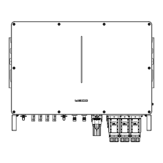
2.3 Terminals of inverter Figure 2-3 Terminal Description DC switch DC switch for PV1 and PV2 DC Input terminal PV input port DC switch DC switch for PV3 and PV4 Battery input terminal Battery connector COM2 COM2 interface for Meter/BMS/RS485/DRED/DO Connector COM1 COM1 interface for WIFI module terminal COM3... -
Page 15: System Topology
2.4 System Topology For proper operation of the EPS load, make sure that the maximum load power of the EPS is within the limits of the inverter, otherwise the system will not be able to support the EPS in case of power failure and an overload alarm may occur. (Refer to the product data sheet). -
Page 16: Pre-Installation
3 Pre-installation 3.1 Check the outer packaging Before unpacking the inverter, check the outer packaging for visible damage, such as holes, cracks, or other signs of possible damage inside, and check the inverter model. If the packaging has abnormalities or the inverter model does not match, do not open it and contact your dealer as soon as possible. - Page 17 Torque screwdriver (head: M4, Wire strippers Diagonal pliers M6; Torque range: 0N•m~ 5N•m). Tool knife Rubber hammer Wire cutters Cable ties Open Wrench (Model: H4TW0001; Crimping pliers (Model: Manufacturer: Amphenol). H4TC0001; Manufacturer: Amphenol). Markers Multimeter (DC voltage range ≥ vacuum cleaner 600V DC).
-
Page 18: Installation Environment Requirements
The inverter should be installed in a well-ventilated environment to ensure good heat dissipation. (Do not install the inverter outside without any weather protection/shielding. WeCo suggests that installation take place in dedicated technical rooms in order to maximize the safety and durability of the system. -
Page 19: Installation Space Requirements
Installation space requirements When installing the inverter, a certain amount of space should be reserved around the inverter to ensure that there is enough space for installation and heat dissipation. And do not install the inverter too high, Installing the inverter too high is not conducive to heat dissipation, installation, and maintenance. -
Page 20: Cable Preparation
The switches below are recommended by WECO. For any other selection, please choose the cable according to local regulations. Relevant Cable & wires introduction The cables shown below are recommended by WECO but must still be validated by the design engineer in your electrical design. Choose the cable according to local standards and design specifications. -
Page 21: Installation
4 Installation Before installing the TK series inverter, please read this manual carefully. Danger! Before making the electrical connection, make sure that all the switches of the inverter are in "OFF" state, otherwise the high voltage of the inverter may cause the risk of electric shock. -
Page 22: Installation Steps
4.2 Installation Steps • Step 1: Install the TK inverter on a wall. • Step 2: Connect the PE cable to TK inverter • Step 3: Connect the PV strings to TK inverter. • Step 4: Connect battery to TK inverter. •... -
Page 23: Step 2: Connect The Pe Cable To Inverter
Step 2: Connect the PE cable to inverter. (a) Make the OT terminals for PE cable. (b) Protect the the conductor with a heat shrink tube. (c) Connect to the PE terminal on the right side of inverter inside. 1. Make the OT terminal for “PE” cable. 2. -
Page 24: Step 4: Connect The Battery To Tk Inverter
Step 4: Connect the Battery to TK inverter. Make the Bat connector: (a) Strip the 10mm conductor of Bat and insert the conductor into the Pin. (b) Using a crimping tool to crimp the cable end of Bat (c) Put the Bat+ end to the Bat+ connector and fasten the screw. Connect the power cable of the HV Box to TK inverter. - Page 25 Connect the Communication cable between Battery and TK. Connect the battery to the TK COM2 with a special RJ45 cable from the accessory. (a) Thread the RJ45 plug of appropriate length through the swivel nut, and insert it into the open side of the rubber gasket.
-
Page 26: Step 5: Connect The Ac Cables To Tk Inverter
Step 5: Connect the AC cables to TK inverter a. Make the PIN terminal ends for L1, L2, L3, N, PE of AC cables. b. Use a crimping tool to crimp all cable ends. c. Run the cable gland and connect it to the connector. d. -
Page 27: Step 6: Connect Meter To Tk Inverter
Step 6: Connect Meter to TK inverter The current Transformer, also called CT, must be installed on the L wires between of the power grid. The Meter can be installed in the AC combiner box or other appropriate places. Standard CT cable with length of 2m, it’s fixed and can’t be extended. - Page 28 Connect the Communication cable between Meter and TK inverter. Connect the battery to the TK COM2 with a special RJ45 cable from the accessory. (a) Thread the RJ45 plug of appropriate length through the swivel nut, and insert it into the open side of the rubber gasket.
-
Page 29: System Commissioning
5 System Commissioning 5.1 Power-up checklist Note! ⚫ Please check the following checklist before turning on the system for the first time; otherwise, the device may be dangerous or damaged. ⚫ Always consult local regulations, wear appropriate personal protective equipment during operations for your own safety. ⚫... -
Page 30: System Power Up
5.2 System power up Prerequisites Before closing the AC switch between the inverter and the grid, it is necessary to measure whether the AC voltage on the grid side of the AC switch is within the range allowed by the inverter. Procedure Step 1: Turn on the inverter to activate the WiFi device and configure the inverter. - Page 31 c. Fill in the account and password and Click “Sign In”. Step 3: Add Plant on Noor APP a. Click “Add Plant”. b. Fill in the Plant info and Click “Save”.
- Page 32 Step 4: Add Device on the Plant and config the WIFI module a. Click “Add Device”. b. Click the “Datalogger”. c. Scan the QR code of WIFI module or manual input WIFI module SN number and Click “Adding” to finish add device. d.
- Page 33 Step 5: Inverter setting a. Click the icon and “Basic Setting” to enter the inverter basic setting page. b. Click the “Expert Setting” and input the password to enter the advanced setting page.
-
Page 34: Energize The System
5.4 Energize the system After finishing all the commission steps, installer can power on the inverter step by step. Step 1: If the inverter is connected to the battery, close the battery breaker first and then turn on the battery. Step 2: If there is a PV breaker between the inverter and the photovoltaic string, close the breaker. -
Page 35: System Maintenance
6 System Maintenance 6.1 Routine Maintenance In order to ensure that the inverter can operate well for a long time, it is recommended to maintain it routinely as described in this section. Caution! ⚫ Perform system power-down operations while performing maintenance such as system cleaning, electrical connections, grounding reliability, etc. -
Page 36: Power Down The System
6.2 Power down the system Warning! ⚫ After the inverter is powered down, there is still residual power and heat in the chassis, which may cause electric shock or burns. Therefore, after 15 minutes of powering down the inverter system, wear protective gloves before operating the inverter. ⚫... -
Page 37: Troubleshooting
6.4 Troubleshooting The fault messages and their corresponding troubleshooting methods are listed below: Error/Fault Description Solution Message (1). Confirm whether the grid supply is lost. Grid power outage, AC switch or circuit is Grid Lost disconnected. (2). Check whether the AC breaker and terminal are well connected. (1). - Page 38 (1). Restart the inverter. AC Transducer Fault AC transducer got abnormal (2). If the problem persists, contact the installation company. (1). Use multimeter to measure the voltage between N&PE cable on AC side. If the voltage is higher than 10V, which means the neutral or Self-checking of internal relay got failed.
-
Page 39: Storage & Care
Updating the firmware is critical to optimize inverter performance and warranty. Normally the WECO team updates the system remotely, so always keep the inverter online to avoid missing the update. During the upgrade, the system may operate in bypass mode (directly using mains power). Make sure the inverter is in normal condition and the Internet connection is stable, then press the update button in the NOOR application to start the system update. -
Page 40: Inverter Disposal
PV input lines, battery input lines, AC output lines, and protective grounding cables. Step 3: Remove the screws securing the inverter. Note: Please note that for any reason, personnel or installer should not disassemble/demolish the inverter without WECO's permission, otherwise the device will not be under warranty. -
Page 41: Appendix A Abbreviations
Appendix A abbreviations Alternating Current Direct Current Identifier Light Emitting Diode LVRT Low Voltage Ride-Through MPPT Maximum Power Point Tracking Personal Computer Protective Earthing Photovoltaic Residual Current Device Relative Humidity Serial Number THDI Total Harmonic Current Distortion WEEE Waste Electrical and Electronic Equipment WiFi Wireless Fidelity... -
Page 42: Appendix B Label Description
Appendix B Label Description Nameplate... -
Page 44: Appendix C Technical Datasheet
Appendix C Technical Datasheet TK-25K-XL TK-30K-XL TK-36K-XL TK-40K-XL TK-50K-XL PV Input Start-up voltage (V) 1000* 1000* 1000* 1000* 1000* Max. DC input voltage (V)* Rated DC input voltage (V) 200-850* 200-850* 200-850* 200-850* 200-850* MPPT voltage range (V)* No. of MPP trackers No. - Page 45 Rated output apparent power (kVA) 25.0 30.0 36.0 40.0 50.0 Max. output apparent power (kVA) 27.5 33.0 39.6 44.0 55.0 Rated output current (A) 38.0 43.5 52.0 60.0 75.0 Max. output current (A) 42.0 50.0 60.0 66.0 83.0 UPS switching time <20ms <20ms <20ms...
- Page 46 Standby self-consumption (W) <15 <15 <15 <15 <15 Topology Transformerless Transformerless Operating Temperature Range (°C) -30~60 -30~60 -30~60 -30~60 -30~60 0~100 0~100 0~100 0~100 0~100 Relative Humidity (%) Operating Altitude (m) 3000(>3000m derating) 3000(>3000m derating) Cooling Smart fan Smart fan <50 <50 <50...
- Page 47 TK-40K-HC TK-50K-HC PV Input Start-up voltage (V) Max. DC input voltage (V)* 1000* 1000* Rated DC input voltage (V) MPPT voltage range (V)* 200-850* 200-850* No. of MPP trackers No. of DC inputs per MPPT 60*2 60*2 Max. input current (A) Max.
- Page 48 Rated output apparent power (kVA) 40.0 50.0 Max. output apparent power (kVA) 44.0 55.0 Rated output current (A) 60.0 75.0 Max. output current (A) 66.0 83.0 UPS switching time <20ms <20ms Rated output voltage (V) 3L/N/PE,220/380V;230/400V;240/415V Rated output frequency (Hz) 50/60 50/60 Peak output apparent power (kVA)
- Page 49 Weight (KG) IP65 IP65 Protection degree <15 <15 Standby self-consumption (W) Topology Transformerless Transformerless Operating Temperature Range (°C) -30~60 -30~60 Relative Humidity (%) 0~100 0~100 Operating Altitude (m) 3000(>3000m derating) Cooling Smart fan <50 <50 Noise Level (dB) Display OLED & LED Communication CAN,RS485,WiFi/LAN(Optional) *PV Max.input voltage is 850V.
-
Page 50: Appendix D Working Mode & Light Language
Appendix D Working Mode & Light Language The TK inverter can manage PVs through the use of MPPT, can perform three-phase DC to AC conversion through the inverter circuit, and has a surge protection function on both the DC and AC sides. The TK inverter supports the use of storage batteries;... - Page 51 Description of the LEDs The LED Bar is described in the following table Equipment status Light language remarks Standby Blink blue light once for 6s (3S lights on,3S lights off) The device is normal and in standby On-Grid Work Blinking green light once for 6s (3S lights on, 3S lights off) Off-Grid Work Blinking green light once for 3s (0.5S lights on, 2.5S lights off)
- Page 52 Mode Type Scenario Brief Description When the load consumption exceeds the Pmax, the inverter will take power from the battery and PV to supply power to the load to compensate for the power that exceeds the Pmax. *To realize the “Peak load Shifting” function, the load power that exceeded Pmax has to be within the inverter max output power, otherwise, the inverter will only output the max power which allowed.
- Page 53 Mode Type Scenario Brief Description Inverter will use power from PV and battery to supply loads in the predetermined period and the insufficient part will be supplied by the grid. In the purely off-grid mode, power from PV will supply the back-up loads first and then charge the battery if there's surplus power.
-
Page 54: Appendix E Noor App User Guide
Appendix E Noor APP User Guide App Introduction Function Through the application, alarm querying, parameter configuration, daily maintenance, debugging and other functions can be realised, and it is a convenient maintenance platform. Connection method Precondition Make sure the WIFI module is correctly connected to the ESY inverter. After the DC side or AC side of the inverter is power on, it can be connected to the APP through WIFI module and external router: Statement... -
Page 55: Register A Noor App Account
Register a Noor APP account Precondition The DC or AC side of the inverter is powered on. WIFI module is connected to the ESY inverter. The phone is connected to the network. Procedure If you do not have a Noor App user account, register following these steps: Steps:... -
Page 56: Build A Power Station Wizard
Logout APP Steps: Click " " in the upper left corner of the main page, and a pop-up page will appear on the left side. On the pop-up page that slides out, click the " " icon to log out. Build a Power Station Wizard Precondition After completing the device commissioning, you can use Noor App to create a power station and configure the basic... -
Page 57: Add New Device
Add a power station Step1: Click " " in the upper left corner of the main page, and a page will slide out from the left side. Step2: Click on the "Plant Management" button in the slide-out page to view the power station list. Step3: Click the "+"... - Page 58 Step 6: After clicking “Smart Config” follow the steps below to connect the inverter to the local internet connection.
-
Page 59: Check The Plant Status
Check the plant status The Noor App provides an overview of the power station, real-time status overview of the power station, energy output and consumption, revenue, energy flow diagrams, and other information. View the details of the plant After logging in to the App, you can view the details of the current plant, or you can click the " "... -
Page 60: Fault Message
Running Info: Display detailed real-time operational information of the device system, such as voltage, current, power, etc. Link to Manuals: Link to WECO company website from which the related documentations of ESY serials inverter can be viewed or download. Plant Management: View the list of plants and perform adding, deleting and editing of corresponding plant. -
Page 61: Energy Information
Energy Information On the main interface, select "Energy charts" to view energy information, as shown below. Select time: Click the " " area to select the data view on the specified date. Select parameters: Click the " " area to select the parameters that need to be viewed for comparative analysis. -
Page 62: Set Working Mode
Set working mode In the inverter setting page, three working modes can be configured for the current power station: Auto mode, Peak Shaving and Battery Priority. The home page can display the working mode status of the current power station. Basic Setting>>Work Mode>>Peak Shaving>>Enter edit Basic Setting>>Work Mode>>Mode Select Auto mode... -
Page 63: Date And Time Setting
Date & Time setting Basic Setting>>Date and Time Setting Date: Current date. The inverter's statistical function will be performed based on this set date. Time: The current time, the system's planning mode, will match this set time. Battery Setting Set Battery Type In the battery type, two types of batteries can be configured: Lithium and Lead-acid. - Page 64 > Expert Setting” tabs, remote parameter settings can be made for the device system under the current plant. The configuration page can be switched by sliding left and right. Note! Expert Setting is available for authorized installer or engineer to operate. Please contact to the WECO service support for Expert Setting password.
-
Page 65: Grid Setting
Sys Setting Settable functions: EPS Enable, PV Input Type, ISO Enable, ARC enable, Anti Reflux, Inverter AC Power (In/out) EPS Enable:EPS enable switch. After setting the enable switch, the load will output and provide power after the inverter is off the grid. ISO Enable: Insulation detection enable switch. - Page 66 Auto Test If choose the Italy grid standard (CEI-021INTERNA), the Auto test function will be presented, and the inverter AUTO test can be performed. Expert Setting>>Grid Setting>>CEI-021INTERNA(Italy Grid Standard)>>Auto Test...
-
Page 67: Device Running Information
Device running information You can view the detailed real-time operation information of the devices under the current plant such as basic information, photovoltaic, power grid, battery, and load, generator information. Procedure: On the “Home Page” > Click > “Running Info” tabs, you can view detailed real-time run information of the device system under the current plant, such as voltage, current, power, etc. -
Page 68: Plant Management
Note! When the user or installer decides to remove and delete the device/inverter from plant, after the operation of deleting on Noor APP, please note that any personnel or installer do not disassemble / tear down the inverter without authorization, otherwise the device will not be in warranty. - Page 69 Edit plant information According to the actual situation, the name of the plant, the address of the plant and other information can be edited. Procedure: Step1:Click the icon in the upper left corner area of the homepage, and the page will pop up on the left side. Step2:Click "Plant Management"...
-
Page 70: Link To Manuals
Link to Manuals There are documentations about inverter’s introduction, instruction on WECO Company website. By Noor App you can easily access to the website for any documentations about the ESY serials inverter to be viewed or download for your further reference. -
Page 71: Account Management
Account Management This page is suitable for account changes, including Personal Avatar, Name, Email and password. Procedure: Step1:Click "Account Management" to enter Account Management page. Step2:Modify the relevant content according to your actual needs. Setting This page is suitable for account cancel and APP detail review for Service Agreement and Privacy Policy. Cancel Account Procedure: Step1:Click "Setting"...
Need help?
Do you have a question about the TK Series and is the answer not in the manual?
Questions and answers