Erbe VIO 3 Service Manual
Hide thumbs
Also See for VIO 3:
- Manual (124 pages) ,
- Notes on use (124 pages) ,
- Service manual (88 pages)

Related Manuals for Erbe VIO 3


Summary of Contents for Erbe VIO 3
- Page 1 SERVICE MANUAL ® V 1.1.x V 1.3.x V 1.4.x ELECTROSURGERY 80116-939_V25148 2023-11...
- Page 3 SERVICE MANUAL ®...
- Page 4 Erbe Elektromedizin GmbH owns these trademarks in the United States: APC, AUTO CUT, BICLAMP, ENDO CUT, ERBE, ER- BECRYO, erbe power your performance., ERBEJET, ERBELIFT, ERBOKRYO, FIAPC, FORCED COAG, HYBRIDAPC, HYBRIDKNIFE, ICC 200, KYRON, NESSY, NESSY Ω, PRECISE APC, PULSED APC, REMODE, SOFT COAG, SWIFT COAG, THERMO SEAL, TWIN CO- AG, VIO.
-
Page 5: Table Of Contents
Table of Contents Table of Contents Safety information ........7 Classification of the safety information. - Page 6 Table of Contents Abbreviations of Error displays........29 APC/APC-A error .
-
Page 7: Safety Information
Table of Contents CHAPTER 1 Safety information Classification of the safety information DANGER indicates an imminently hazardous situation which, if not avoided, will result in death or serious injury. WARNING indicates a potentially hazardous situation which, if not avoided, could result in death or serious injury. CAUTION indicates a potentially hazardous situation which, if not avoided, may result in minor or moderate injury. -
Page 8: Protection From The Risk Of Electric Shock
Connect the unit to a properly installed grounded power outlet. Only connect the unit using an Erbe power cord (see the user manual for REF numbers). Alternatively: power cables with a length of no more than 5 m can be used in accordance with country/region requirements, e.g. - Page 9 1 • Safety information WARNING Open unit intentionally carrying voltage for servicing work. Risk of electric shock and resulting consequential injuries. The unit/objects in the vicinity of the unit can be damaged. Under no circumstances should you touch live compo- ...
-
Page 10: Electrostatically Sensitive Components
System adjustments, modifications, and repair work may only be performed by Erbe or persons trained and autho- rized by Erbe. If any unauthorized work as stated above is performed, Erbe accepts no liability and warranty rights become void. -
Page 11: Modifications
2 • Modifications CHAPTER 2 Modifications From version 1.3.x Hardware Component affected Description of the modification New UGM From software version 1.3.1 a new Universal Generator Module is installed. The design modification has an impact on the spare parts order. Software Component affected Description of the modification... - Page 12 2 • Modifications / 132...
-
Page 13: Controls
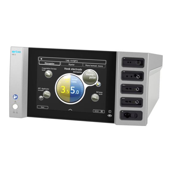
3 • Controls CHAPTER 3 Controls Note: This chapter contains an overview of the controls of the unit(s). The relevant User Manual for the unit(s), knowledge of which is assumed for servicing work, provides detailed information about how to use the unit(s). Controls at the front Fig. -
Page 14: Controls At The Rear
3 • Controls Controls at the rear Fig. 3-2 Footswitch sockets ECB sockets (Erbe Communication Bus) Grounding terminal pin Power supply module with fuses and cover / 132... -
Page 15: Technical Data
4 • Technical Data CHAPTER 4 Technical Data Power connection Rated supply voltage 100 – 120 VAC (±10%) / 220 – 240 VAC (±10%) Rated supply frequency 50 Hz / 60 Hz Line current (averaged) max. 6.3 A / 2.5 A Power input in standby mode <... - Page 16 4 • Technical Data Ethernet Ethernet optional (deactivated as standard) Dimensions and weight Width x height x depth 415 x 215 x 375 mm (16.3" x 8.5" x 14.8") Weight 12 kg (26 lbs. 7 oz.) Display size 10.4 inch Ambient conditions for transport and storage of unit Temperature -30°C to +70°C (-22°F to +158°F)
-
Page 17: Circuit Descriptions
5 • Circuit Descriptions CHAPTER 5 Circuit Descriptions / 132... -
Page 18: Block Diagram
5 • Circuit Descriptions Block diagram Fig. 5-1 / 132... -
Page 19: Description Of The Various Assemblies
5 • Circuit Descriptions Description of the various assemblies UI = User Interface The User Interface provides an interface for the user (in terms of operating the unit). In this respect, the user interface is comprised of several differ- ent components. The specific tasks of the individual components are: GUI component •... -
Page 20: Iim - Instrument Interface Module
5 • Circuit Descriptions IIM – Instrument Interface Module The Instrument Interface Module is used to connect electrosurgical instru- ments to the electrosurgical system. In this respect, the IIM performs the following specific tasks: • Resistance-based activation detection • Half-wave (diode)-based activation detection •... -
Page 21: Mcm - Measure Control Module
5 • Circuit Descriptions MCM – Measure Control Module The Measure Control Module ensures the required types of HF current. In this respect, the MCM performs the following specific tasks: • Measurement of the HF output voltage, and of the HF output current •... -
Page 22: Can Hub
For the connection of external modules, the CAN hub is connected to the SCM. The CAN hub makes the 1 CAN bus connection port available to 5 external connection ports (2 footswitches, 2 ECBs = Erbe Communication Bus, 1 IO card). NS – Nerve Stimulator The Nerve Stimulator module provides a nerve stimulation signal at every socket. -
Page 23: System Settings And "Service" Menu
6 • System settings and "Service" menu CHAPTER 6 System settings and "Service" menu General information System settings This unit has two levels for changing system settings. The first level can be accessed by users and service personnel. The second level can only be ac- cessed by service personnel. - Page 24 6 • System settings and "Service" menu Setting Available from Description Argon V 1.1.x Automatic irrigation: plasma Once it has been plugged into the APC socket, the instrument is auto- module APC matically irrigated with gas / an instrument that has already been plugged into the APC socket is automatically irrigated with gas when the unit starts up.
-
Page 25: Overview Of System Settings 2
6 • System settings and "Service" menu Overview of system settings 2: Protected settings Only accessible for service personnel. Password-protected. Setting Available Description from Maximum activa- V 1.1.x This setting determines the period of time after which activation auto- tion time matically terminates. -
Page 26: Overview: "Service" Menu
V 1.1.x GUI: Graphical User Interface. V 1.1.x IIM1 to 6: Instrument Interface Module, slot 1 to 6 (Slots counted from top to bottom, VIO 3: 1 to 4, APC 3: 5 to 6). V 1.1.x NE: Return electrode. V 1.1.x PSU: Power Supply Unit. -
Page 27: Calling Up System Settings
6 • System settings and "Service" menu Calling up system settings Fig. 6-1 Calling up 1. Call up the "Menu" screen. <Further settings> 2. Call up <Further settings>. The unit shows all settings that can be modified without a password. Calling up 1. -
Page 28: Calling Up The "Service" Menu
6 • System settings and "Service" menu Calling up the "Service" menu Fig. 6-2 1. Call up the "Menu" screen. 2. Call up <Service>. 3. Enter the password VIO3 and confirm with <Entry>. The unit shows all service settings. / 132... -
Page 29: Remedying Malfunctions
System adjustments, modifications, and repair work may only be performed by Erbe or persons trained and autho- rized by Erbe. If any unauthorized work as stated above is performed, Erbe accepts no liability and warranty rights become void. -
Page 30: Apc/Apc-A Error
7 • Remedying malfunctions ERROR list as at: 11/2023 APC/APC-A error Display on the unit: APC or APC-A, detecting module: GCM Error code Description Additional information Action CRC check triggers an Restart the unit. If the alarm. error occurs again, repro- gram the unit. - Page 31 7 • Remedying malfunctions Display on the unit: APC or APC-A, detecting module: GCM Error code Description Additional information Action Operating voltage Check PSU, interconnec- 12 V is faulty. tion, and GCM. Operating voltage Restart the unit. If the 5 Vcan is faulty. error occurs again, check the GCM.
- Page 32 7 • Remedying malfunctions Display on the unit: APC or APC-A, detecting module: GCM Error code Description Additional information Action PowerOnSelfcheck: Check GFS and GCM, Error during offset correc- replace defective assem- tion of amplified differen- bly. tial pressure sensor. SelfCheck: Check GFS and GCM, Mass flow sensor error.
- Page 33 If the advisory message index for detailed errors. error memory, only PoDED persists and can be repro- is sent. duced, notify Erbe Service. EEPROM handler – no Not saved by GCM in the If the advisory message handler. error memory, only PoDED persists and can be repro- is sent.
- Page 34 If the advisory message callback. error memory, only PoDED persists and can be repro- is sent. duced, notify Erbe Service. EEPROM handler – no Not saved by GCM in the If the advisory message callback for EEPROM read. error memory, only PoDED persists and can be repro- is sent.
- Page 35 7 • Remedying malfunctions Display on the unit: APC or APC-A, detecting module: GCM Error code Description Additional information Action CAN error in physical layer Not saved by GCM in the If the advisory message – CRC error. error memory, only PoDED persists and can be repro- is sent.
- Page 36 7 • Remedying malfunctions Display on the unit: APC or APC-A, detecting module: GCM Error code Description Additional information Action APC-A Output pressure > 2 bar Check the accessories. (rel) during activation. If the error occurs again, [Instrument blockage?] check APC socket, hose connections, pneumatic block and GFS.
-
Page 37: Eip/Eip-A Error
7 • Remedying malfunctions EIP/EIP-A error Display on the unit: EIP or EIP-A, detecting module: Erbe irrigation pump EIP 2 Error code Description Additional information Action Not available. EIP-A CRC error. Reprogram EIP 2 main- board or replace main- board. -
Page 38: G/G-A Error
7 • Remedying malfunctions G/G-A error Display on the unit: G or G-A, detecting module: UGM Error code Description Additional information Action CRC check triggers an Restart the unit. If the alarm. error occurs again, repro- gram the unit. Oscillator clock fault. From V 1.1.x. -
Page 39: I/I-A Error
Note: I errors are output with the identification number of the originating socket slots = I X (slots are counted from top to bottom -> VIO 3: 1, 2, 3, 4, APC 3: 5, 6). The NE slot is not included during counting as this assembly generates its own error messages (see N errors). - Page 40 IIM and socket. 1-wire, type incorrectly Check the accessories. If detected. the error persists, check IIM and socket. 1-wire, no Erbe instru- Check the accessories. If ment. the error persists, check IIM and socket. Short circuit, IK (instru- Check the accessories. If ment recognition) line.
- Page 41 7 • Remedying malfunctions Display on the unit: I or I-A, detecting module: IIM Error code Description Additional information Action Protocol version not com- From V 1.1.x. Check the accessories. If patible with 1-wire. the error persists, check IIM and socket. One or more buttons Check the accessories.
-
Page 42: M/M-A Error
7 • Remedying malfunctions M/M-A error Display on the unit: M or M-A, detecting module: MCM Error code Description Additional information Action CRC check of the program Restart the unit. If the code in the boot loader error occurs again, repro- signals an error. - Page 43 7 • Remedying malfunctions Display on the unit: M or M-A, detecting module: MCM Error code Description Additional information Action Software execution error Software execution error. Restart the unit. If the when calling the Count- error occurs again, repro- DownTimer. gram the unit.
- Page 44 7 • Remedying malfunctions Display on the unit: M or M-A, detecting module: MCM Error code Description Additional information Action Offset error of the PSU The offset of the voltage Check PSU. voltage value. sensor or of the PSUADC voltage input is outside the default value.
- Page 45 7 • Remedying malfunctions Display on the unit: M or M-A, detecting module: MCM Error code Description Additional information Action UGM discharge circuit Activation defect of the Check UGM and PSU. permanently off. discharge transistor. Short circuit at HF output Check UGM.
- Page 46 7 • Remedying malfunctions Display on the unit: M or M-A, detecting module: MCM Error code Description Additional information Action Short circuit during HF Short circuit at HF current Check UGM. current measurement. sensor or at HFADC cur- rent input. HF voltage value on the Defect of the HF voltage Check UGM.
- Page 47 7 • Remedying malfunctions Display on the unit: M or M-A, detecting module: MCM Error code Description Additional information Action Nominal voltage of the Similar error pattern as in Check PSU and UGM. power supply unit reaches the case of continuous the maximum for the acti- modes and error 39.
- Page 48 7 • Remedying malfunctions Display on the unit: M or M-A, detecting module: MCM Error code Description Additional information Action highCUT, bipolar (no load): Ensure that NaCl solution Instrument not dipped is used as the irrigation into NaCl solution or solution.
-
Page 49: N/N-A Error
7 • Remedying malfunctions N/N-A error Display on the unit: N or N-A, detecting module: NM Error code Description Additional information Action CRC check triggers an Restart the unit. If the alarm. error occurs again, repro- gram the unit. ErrorHandler Buffer Over- Restart the unit. - Page 50 7 • Remedying malfunctions Display on the unit: N or N-A, detecting module: NM Error code Description Additional information Action EEPROM CRC is faulty. CRC of the offset parame- Restart the unit. If the ters does not match. error occurs again, check the NM.
- Page 51 7 • Remedying malfunctions Display on the unit: N or N-A, detecting module: NM Error code Description Additional information Action HF 2 current sensor is Measured value detection Check NM. faulty. signals invalid values at sensor NE2. Faulty circuit. Solid state relay not con- Check NM.
- Page 52 ERROR handler – no valid Is not output as a warning If the advisory message index for detailed errors. by the NM, only sent as an persists and can be repro- entry to Chrono. duced, notify Erbe Service. / 132...
- Page 53 If the advisory message handler. by the NM, only sent as an persists and can be repro- entry to Chrono. duced, notify Erbe Service. EEPROM handler – no Is not output as a warning If the advisory message valid handler.
- Page 54 CAN protocol violation as If the advisory message – bit stuff error. no stuff bit was received. persists and can be repro- duced, notify Erbe Service. CAN error in physical layer CRC of the CAN message If the advisory message – CRC error.
- Page 55 7 • Remedying malfunctions Display on the unit: N or N-A, detecting module: NM Error code Description Additional information Action NESSY: Symmetry error. Check the alignment of the return electrode. Fol- low the information pro- vided in the User Manual. If the error persists, check the return electrode accessories and NM.
-
Page 56: P/P-A Error
7 • Remedying malfunctions P/P-A error Display on the unit: P or P-A, detecting module: PSU Error code Description Additional information Action CRC check triggers an Restart the unit. If the alarm. error occurs again, repro- gram the unit. ErrorHandler Buffer Over- Restart the unit. - Page 57 If the advisory message index for detailed errors. by the PSU, only sent as persists and can be repro- an entry to Chrono. duced, notify Erbe Service. EEPROM handler – no Is not output as a warning If the advisory message handler.
- Page 58 If the advisory message valid address. by the PSU, only sent as persists and can be repro- an entry to Chrono. duced, notify Erbe Service. EEPROM handler – no Is not output as a warning If the advisory message callback.
- Page 59 7 • Remedying malfunctions Display on the unit: P or P-A, detecting module: PSU Error code Description Additional information Action CAN error in physical layer Is not output as a warning If the advisory message – stuck at dominant by the PSU, only saved in persists and can be repro- (dominant bus level too the EEPROM.
-
Page 60: S/S-A Error
7 • Remedying malfunctions S/S-A error Display on the unit: S or S-A, detecting module: SCM Error code Description Additional information Action Checksum calculation Faulty software. Restart the unit. If the application check triggers error occurs again, repro- an alarm. gram the unit. - Page 61 7 • Remedying malfunctions Display on the unit: S or S-A, detecting module: SCM Error code Description Additional information Action Power failure. Faulty unit power supply. Check supply input volt- age, power cord and sup- ply input module. If the error persists, replace the PSU.
- Page 62 7 • Remedying malfunctions Display on the unit: S or S-A, detecting module: SCM Error code Description Additional information Action Module X in invalid state Restart the unit. If the at boot. error occurs again, check the affected module. Module X Selfcheck error Restart the unit.
- Page 63 7 • Remedying malfunctions Display on the unit: S or S-A, detecting module: SCM Error code Description Additional information Action Second signal detected Unsupported unit con- An incompatible module with higher priority. nected to the ECB. was connected to the sys- tem.
- Page 64 7 • Remedying malfunctions Display on the unit: S or S-A, detecting module: SCM Error code Description Additional information Action Occurs when a modified Check whether all config- socket configuration has ured sockets in the sys- been detected. (e.g. due tem have been correctly to replacement or retrofit- detected.
- Page 65 7 • Remedying malfunctions Display on the unit: S or S-A, detecting module: SCM Error code Description Additional information Action No footswitch assigned on Assign footswitch. activation. No mode for activation Set mode. source assigned on acti- vation. Where the end of activa- Terminate activation and tion is regular, a new grip the tissue again.
- Page 66 7 • Remedying malfunctions Display on the unit: S or S-A, detecting module: SCM Error code Description Additional information Action One pedal ReMode Information, no fault con- footswitch disconnected. dition. Two pedal ReMode Information, no fault con- footswitch ready for oper- dition.
-
Page 67: U/U-A Error
7 • Remedying malfunctions U/U-A error Display on the unit: U or U-A, detecting module: UI Error code Description Additional information Action DCB communication time- It has taken too long for Check control unit, cables, out. the Data/Device Control and mainboard. Block to receive a mes- sage from the SCM during activation. - Page 68 7 • Remedying malfunctions / 132...
-
Page 69: Maintenance And Servicing
The technical safety check is an extensive preventative test that verifies various aspects of the device. Functional testing is required to ensure that the device is safe and ready for operation. Erbe documentation can be pro- vided with current specifications. Testing must be performed per manufac- turers’... -
Page 70: Technical Safety Check
8 • Maintenance and servicing Technical safety check For this unit the following technical safety checks have been stipulated: • Visual inspection of Unit, Accessories, User Manual, and Labels • Testing the grounded conductor as per IEC 62353 • Leakage current testing as per IEC 62353 •... -
Page 71: Spare Parts
9 • Spare parts CHAPTER 9 Spare parts Hardware 30160-105 (2) 51400-022 (1) 30160-105 (2) 30160-105 (2) 30160-105 (2) 51501-099 (1) Fig. 9-1 / 132... - Page 72 9 • Spare parts Fig. 9-2 / 132...
- Page 73 9 • Spare parts Fig. 9-3 / 132...
- Page 74 9 • Spare parts Fig. 9-4 / 132...
- Page 75 9 • Spare parts Fig. 9-5 / 132...
- Page 76 9 • Spare parts Fig. 9-6 / 132...
- Page 77 9 • Spare parts Fig. 9-7 / 132...
- Page 78 9 • Spare parts 40160-002 (5) 40160-106 (1) 30160-810 (5) SBL - Socket Backlight 40160-105 (1) 30160-105 (4) EJOT 30 x 25 Fig. 9-8 / 132...
- Page 79 9 • Spare parts Fig. 9-9 / 132...
- Page 80 9 • Spare parts Fig. 9-10 / 132...
-
Page 81: Wiring
9 • Spare parts Wiring Fig. 9-11 / 132... -
Page 82: Circuit Boards
9 • Spare parts Circuit Boards Fig. 9-12 / 132... -
Page 83: Socket Modules
9 • Spare parts Socket modules Bipolar sockets Erbe Art. No. 20160-003 Socket module BI 2Pin 22–28, 8/4 Fig. 9-13 Monopolar sockets Erbe Art. No. 20160-001 Socket module MO 3Pin, 9/5 Fig. 9-14 Erbe Art. No. 20160-002 Socket module MO 3Pin-Bovie Fig. -
Page 84: Multifunction Sockets
9 • Spare parts Multifunction sockets Erbe Art. No. 20160-004 MF socket module Fig. 9-16 Erbe Art. No. 20160-005 MF-U socket module Fig. 9-17 Sockets for return electrode Erbe Art. No. 20160-006 Socket module NE 6 – NE 2Pin, including slide switch to cover the unused socket input. -
Page 85: Circuit And Component Diagrams
10 • Circuit and Component diagrams CHAPTER 10 Circuit and Component diagrams German English CAN-Buchsenplatine (Signale und CAN socket board (signals and Spannungen werden auf MB erze- voltages are generated on the ugt) Fußschalter-Buchsenplatine (Sig- Footswitch socket board (signals nale und Spannungen werden auf and voltages are generated on the MB erzeugt) Fußschalter Buchsen... -
Page 86: Mainboard: 30160-800
10 • Circuit and Component diagrams Mainboard: 30160-800 Fig. 10-1 / 132... - Page 87 10 • Circuit and Component diagrams Mainboard: 30160-800 Fig. 10-2 / 132...
- Page 88 10 • Circuit and Component diagrams Mainboard: 30160-800 Fig. 10-3 / 132...
- Page 89 10 • Circuit and Component diagrams Mainboard: 30160-800 Fig. 10-4 / 132...
- Page 90 10 • Circuit and Component diagrams Mainboard: 30160-800 Fig. 10-5 / 132...
- Page 91 10 • Circuit and Component diagrams Mainboard: 30160-800 Fig. 10-6 / 132...
-
Page 92: Mainboard: 40160-800
10 • Circuit and Component diagrams Mainboard: 40160-800 Fig. 10-7 / 132... -
Page 93: Power Supply Unit: 30160-801
10 • Circuit and Component diagrams Power Supply Unit: 30160-801 B82726S2163N002 Fig. 10-8 / 132... - Page 94 10 • Circuit and Component diagrams Power Supply Unit: 30160-801 Fig. 10-9 / 132...
- Page 95 10 • Circuit and Component diagrams Power Supply Unit: 30160-801 Fig. 10-10 / 132...
- Page 96 10 • Circuit and Component diagrams Power Supply Unit: 30160-801 Fig. 10-11 / 132...
- Page 97 10 • Circuit and Component diagrams Power Supply Unit: 30160-801 Fig. 10-12 / 132...
- Page 98 10 • Circuit and Component diagrams Power Supply Unit: 30160-801 Fig. 10-13 / 132...
- Page 99 10 • Circuit and Component diagrams Power Supply Unit: 30160-801 Fig. 10-14 / 132...
-
Page 100: Power Supply Unit: 40160-801
10 • Circuit and Component diagrams Power Supply Unit: 40160-801 Fig. 10-15 / 132... -
Page 101: Universal Generator Module: 30160-802/ -803
10 • Circuit and Component diagrams Universal Generator Module: 30160-802/ -803 220p Fig. 10-16 / 132... - Page 102 10 • Circuit and Component diagrams Universal Generator Module: 30160-802/ -803 Fig. 10-17 / 132...
- Page 103 10 • Circuit and Component diagrams Universal Generator Module: 30160-802/ -803 Fig. 10-18 / 132...
-
Page 104: Universal Generator Module: 40160-802 / -803
10 • Circuit and Component diagrams Universal Generator Module: 40160-802 / -803 Fig. 10-19 / 132... -
Page 105: Instrument Interface Module: 30160-805
10 • Circuit and Component diagrams Instrument Interface Module: 30160-805 Fig. 10-20 / 132... - Page 106 10 • Circuit and Component diagrams Instrument Interface Module: 30160-805 Fig. 10-21 / 132...
- Page 107 10 • Circuit and Component diagrams Instrument Interface Module: 30160-805 Fig. 10-22 / 132...
- Page 108 10 • Circuit and Component diagrams Instrument Interface Module: 30160-805 Fig. 10-23 / 132...
-
Page 109: Instrument Interface Module: 40160-805
Titel: Doc. Nr.: Prepreg > 250μm Layer 3: Cu = 35μm IIM HW V1.0 PCB D081353 Core > 700μm ERBE Nr.: Doc. Version: Layer 2: Cu = 35μm Prepreg > 250μm 40160-805 Layer 1 (BOTTOM): Cu = 35μm Artikel Nr.: Ersteller: PCB Thickness 1600μm +-10%... -
Page 110: Nessy Module: 30160-806
10 • Circuit and Component diagrams Nessy Module: 30160-806 Fig. 10-25 / 132... - Page 111 10 • Circuit and Component diagrams Nessy Module: 30160-806 Fig. 10-26 / 132...
- Page 112 10 • Circuit and Component diagrams Nessy Module: 30160-806 744220 RK1B SP1B Fig. 10-27 / 132...
- Page 113 10 • Circuit and Component diagrams Nessy Module: 30160-806 Fig. 10-28 / 132...
-
Page 114: Nessy Module: 40160-806
Titel: Doc. Nr.: Prepreg > 250μm NM HW V1.0 PCB D081359 Layer 3: Cu = 35μm Core > 700μm ERBE Nr.: Doc. Version: Layer 2: Cu = 35μm 40160-806 Prepreg > 250μm Layer 1 (BOTTOM): Cu = 35μm Artikel Nr.:... -
Page 115: Socket Backlight: 30160-810
10 • Circuit and Component diagrams Socket Backlight: 30160-810 Fig. 10-30 / 132... -
Page 116: Socket Backlight: 40160-810
C105 C115 D104 C107 R105 C106 C118 68.000 mm +-0.2 Titel: Doc. Nr.: SBL HW V1.0 PCB D081368 ERBE Nr.: Doc. Version: 40160-810 Artikel Nr.: Ersteller: A071938 LAURAS Lageninformation: Erstelldatum: Lage 2 (BS; oben) 19.01.2016 Weitergabe sowie Vervielfältigung dieses Dokuments, Verwertung und Mitteilung seines Inhalts sind verboten, soweit nicht ausdrücklich gestattet. -
Page 117: Main Switch: 30160-817
D081396 Elektromedizin GmbH Weitergabe sowie Vervielfältigung dieses Dokuments, Verwertung und Mitteilung seines Inhalts sind verboten, soweit nicht ausdrücklich gestattet.Zuwiderhandlungen verpflichten zum Schadenersatz. Alle Rechte für den Fall der Patent-, Gebrauchsmuster- oder Geschmacks- ERBE Nr.: Ers.für: $1SCM_replaces Blatt: 1 von 30160-817 mustereintragung vorbehalten. -
Page 118: Main Switch: 40160-817
10 • Circuit and Component diagrams Main Switch: 40160-817 40160-817 MS HW V1.0 PCB 17-12-2014 53.016 mm Titel: Doc. Nr.: MS HW V1.0 PCB D081398 ERBE Nr.: Doc. Version: 40160-817 Artikel Nr.: Ersteller: A071952 LAURAS Lageninformation: Erstelldatum: Lage 2 (BS; oben) 26.01.2016... -
Page 119: Foot Switch Can: 30160-807
10 • Circuit and Component diagrams Foot Switch CAN: 30160-807 Fig. 10-34 / 132... -
Page 120: Foot Switch Can: 40160-807
L100 L101 C103 C104 C105 C106 D102 D103 Titel: Doc. Nr.: FS CAN HW V1.0 PCB D081362 ERBE Nr.: Doc. Version: 40160-807 Artikel Nr.: Ersteller: A071934 LAURAS Lageninformation: Erstelldatum: Lage 2 (BS; oben) 19.01.2016 Weitergabe sowie Vervielfältigung dieses Dokuments, Verwertung und Mitteilung seines Inhalts sind verboten, soweit nicht ausdrücklich gestattet. -
Page 121: Ecb Can: 30160-818
10 • Circuit and Component diagrams ECB CAN: 30160-818 Fig. 10-36 / 132... -
Page 122: Ecb Can: 40160-818
ECB CAN: 40160-818 D100 D101 C100 C101 L100 L101 Titel: Doc. Nr.: ECB CAN HW V1.0 PCB D081401 ERBE Nr.: Doc. Version: 40160-818 Artikel Nr.: Ersteller: A071955 LAURAS Lageninformation: Erstelldatum: Lage 2 (BS; oben) 20.01.2016 Weitergabe sowie Vervielfältigung dieses Dokuments, Verwertung und Mitteilung seines Inhalts sind verboten, soweit nicht ausdrücklich gestattet. -
Page 123: Measure Control Module: 30160-804
10 • Circuit and Component diagrams Measure Control Module: 30160-804 Fig. 10-38 / 132... - Page 124 10 • Circuit and Component diagrams Measure Control Module: 30160-804 Fig. 10-39 / 132...
- Page 125 10 • Circuit and Component diagrams Measure Control Module: 30160-804 Fig. 10-40 / 132...
- Page 126 10 • Circuit and Component diagrams Measure Control Module: 30160-804 Fig. 10-41 / 132...
- Page 127 10 • Circuit and Component diagrams Measure Control Module: 30160-804 Fig. 10-42 / 132...
- Page 128 10 • Circuit and Component diagrams Measure Control Module: 30160-804 Fig. 10-43 / 132...
- Page 129 10 • Circuit and Component diagrams Measure Control Module: 30160-804 Fig. 10-44 / 132...
- Page 130 10 • Circuit and Component diagrams Measure Control Module: 30160-804 Fig. 10-45 / 132...
-
Page 131: Measure Control Module: 40160-804
10 • Circuit and Component diagrams Measure Control Module: 40160-804 IC129 Fig. 10-46 / 132... - Page 132 10 • Circuit and Component diagrams / 132...
Need help?
Do you have a question about the VIO 3 and is the answer not in the manual?
Questions and answers