Erbe VIO 300 D Service Manual
Hide thumbs
Also See for VIO 300 D:
- User manual (182 pages) ,
- Service manual (84 pages) ,
- User manual (144 pages)

Related Manuals for Erbe VIO 300 D


Summary of Contents for Erbe VIO 300 D
- Page 1 SERVICE MANUAL ® 300 D V 2.1.x V 2.2.x V 2.3.x V 2.7.x ELECTROSURGERY 80116-288_V23381 2022-04...
- Page 3 SERVICE MANUAL 300 D ®...
- Page 4 Erbe Elektromedizin GmbH owns these trademarks in the United States: APC, APC 300, AUTO CUT, BICLAMP, ENDO CUT, ERBE, ERBECRYO, erbe power your performance., ERBEJET, ERBELIFT, ERBOKRYO, FIAPC, FORCED COAG, HYBRIDAPC, HYBRIDKNIFE, ICC 200, KYRON, NESSY, NESSY Ω, PRECISE APC, PULSED APC, REMODE, SOFT COAG, SWIFT COAG, THERMO SEAL, TWIN COAG, VIO.
-
Page 5: Table Of Contents
ECB (Erbe Communication Bus) ........23... - Page 6 Table of Contents Remedying malfunctions........33 Safety information..........33 ERROR list for VIO system .
-
Page 7: Safety Information
1 • Safety information CHAPTER 1 Safety information Classification of the safety information DANGER indicates an imminently hazardous situation which, if not avoided, will result in death or serious injury. WARNING indicates a potentially hazardous situation which, if not avoided, could result in death or serious injury. CAUTION indicates a potentially hazardous situation which, if not avoided, may result in minor or moderate injury. -
Page 8: Protection From The Risk Of Electric Shock
Connect the unit to a properly installed grounded power outlet. Only connect the unit using an Erbe power cord (see the user manual for REF numbers). Alternatively: power ca- bles with a length of no more than 5 m can be used in accordance with country/region requirements, e.g. - Page 9 1 • Safety information WARNING Open unit intentionally carrying voltage for servicing work. Risk of electric shock and resulting consequential injuries. The unit/objects in the vicinity of the unit can be damaged. Under no circumstances should you touch live compo- ...
-
Page 10: Electrostatically Sensitive Components
System adjustments, modifications, and repair work may only be performed by Erbe or persons trained and autho- rized by Erbe. If any unauthorized work as stated above is performed, Erbe accepts no liability and warranty rights become void. -
Page 11: Modifications
2 • Modifications CHAPTER 2 Modifications From VIO version 2.2.x Hardware No changes Software Component affected Description of the modification Bipolar resection adapter The bipolar resection adapter can be connected to the multifuc- tion socket on the VIO. Supplement to the safety check to test the bipolar resection adapter. -
Page 12: From Vio Version 2.7.X
2 • Modifications From VIO version 2.7.x Hardware No changes Software Component affected Description of the modification Setup 2 settings New setup setting BiCision SC Info. / 110... -
Page 13: Controls
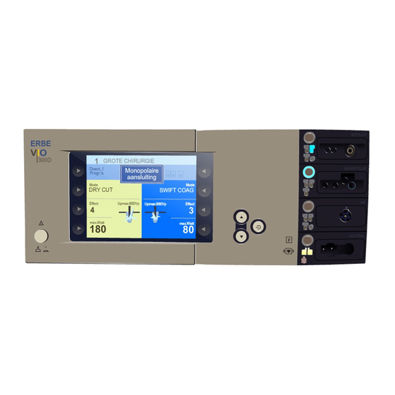
Note: This chapter contains an overview of the controls of the unit(s). The relevant User Manual for the unit(s), knowledge of which is assumed for servicing work, provides detailed information about how to use the unit(s). Controls at the front VIO 300 D Fig. 3-1 Power Switch 2 – 9... -
Page 14: Controls At The Rear
3 • Controls Controls at the rear Fig. 3-2 Footswitch sockets ECB socket (Erbe Communication Bus) Grounding terminal pin Power supply module with fuses / 110... -
Page 15: Technical Data
4 • Technical Data CHAPTER 4 Technical Data Power connection Rated supply voltage 100 V – 120 V (± 10%) 220 V – 240 V (± 10%) Rated supply frequency 50 / 60 Hz 50 / 60 Hz Line current Power input in standby mode 40 watts 40 watts... - Page 16 4 • Technical Data Acclimatizing If the unit has been stored or transported at temperatures below +10 °C (+50 °F) or above +40 °C (+104 °F), the unit will require approx. 3 hours to acclimatize at room temperature. Standards Protective class according to UL 2601-1 Classification according to EC Directive 93/42/EEC II b Protection class as per EN 60 601-1...
-
Page 17: Circuit Descriptions
5 • Circuit Descriptions CHAPTER 5 Circuit Descriptions / 110... -
Page 18: Block Diagram Vio 300 D
5 • Circuit Descriptions Block diagram VIO 300 D Fig. 5-1 / 110... -
Page 19: Description Of The Various Assemblies
5 • Circuit Descriptions Description of the various assemblies Line input The VIO system can be operated with a line voltage of either 220 – 240 V or 100 – 120 V. For this the corresponding value (230 V for a line voltage of 220 –... -
Page 20: Power Supply (High-Voltage Power Supply Unit)
5 • Circuit Descriptions Power supply (high-voltage power supply unit) The high-voltage power supply unit provides the HF generator with a DC voltage which may reach 450 V. It depends on the surgical effect selected and the alternating voltage necessary for this. The line input voltage is directly rectified using a bridge-connected recti- fier. -
Page 21: Hf Generator Ii
5 • Circuit Descriptions HF generator II The high-frequency generator consists of the "HF generator II" circuit board with the power components, and the programmable logic device (CPLD), which is responsible for transistor control but is located on the "CPU+Sensors II" circuit board. The VIO system is only equipped with one generator module. -
Page 22: Cpu + Sensors Ii
5 • Circuit Descriptions CPU + Sensors II The "CPU + Sensors II" circuit board includes the processor controlling all the hardware assemblies in the HF unit, and with the software assemblies ensures the necessary exchange of data. All relevant sensors are also ac- commodated here. -
Page 23: User Interface (Control Panel)
It operates the color display as well as the buttons and dis- plays on the front of the unit. It is the master unit for the Erbe Communi- cation Bus (ECB). The control panel is used to log on all the assemblies, e.g. -
Page 24: Iif (Instrument Interface)
– Multifunction (MF) – – 1. Only relevant for VIO 300 D or in conjunction with a VIO 300 D. Instrument recognition The instrument recognition can identify instruments coded by resistance and read instruments equipped with an electronic memory, transmitting (only relevant for the relevant data to the system. -
Page 25: Nessy2 Ii
5 • Circuit Descriptions NESSY2 II The NESSY2 II assembly measures the electrical resistance between the two connections to the patient plate. In addition, the currents in both con- necting lines are measured. The measured values are transmitted to the "CPU + Sensors II" via an elec- tronically insulated asynchronous serial interface. - Page 26 5 • Circuit Descriptions / 110...
-
Page 27: Setup
6 • Setup CHAPTER 6 Setup General information This unit features two levels for changing settings: • Setup level 1 • Setup level 2 (Service settings) Overview of settings for Setup level 1 Accessible to users and service personnel. Setting Available from Description Brightness... -
Page 28: Overview Of Settings For Setup Level 2 (Service Settings)
6 • Setup Setting Available from Description AUTO START 1 V 2.1.x Input of start delay for the AUTO START function. The start delay value for AUTO START 1 depends on the value entered for AUTO START 2 but is always below the start delay value of AUTO START 2. - Page 29 6 • Setup Setting Available from Description Start screen V 2.1.x Selection of start screen: Guide or List of Programs. Expert mode V 2.1.x If the expert mode is activated, the following settings are also avail- able: – Temperature monitoring for neutral electrodes –...
- Page 30 6 • Setup Setting Available from Description BiCision SC V 2.7.x Extended short circuit detection for BiCision: Info In case an electrical connection is established between the instrument branches (e.g. through the advanced instrument blade) during activa- tion. On: extended short circuit detection is activated, advisory message is shown....
- Page 31 6 • Setup Setting Available from Description V 2.1.x ScreenTest: Tests the function of the screen. A total of 12 rectangular color seg- ments have to be displayed, each of the four in the color ranges red, green and blue. V 2.1.x Error list IIF/NE:...
-
Page 32: Call Up Setup
(a) with the Down button or (b) with the selection button next to the menu item “More”. In the service manual, the variant (a) is used. VIO 300 D Fig. 6-1 Call up Setup level 1 1. Call up "Guide" window. -
Page 33: Remedying Malfunctions
System adjustments, modifications, and repair work may only be performed by Erbe or persons trained and autho- rized by Erbe. If any unauthorized work as stated above is performed, Erbe accepts no liability and warranty rights become void. -
Page 34: A-Errors
7 • Remedying malfunctions Status of the ERROR list: 07.13 A-Errors Recognizing module: A = APC 2 Recog- Error Additional informa- Description Action nizing code tion module Timeout of activation signal. ECB communication inter- rupted. Check or troubleshoot ECB connecting cables. Setup parameters invalid. - Page 35 7 • Remedying malfunctions Recognizing module: A = APC 2 Recog- Error Additional informa- Description Action nizing code tion module Underpressure at selected Check the gas supply (tank, gas input. pressure regulator) and hose connections. If the error per- sists, replace the APC 2 con- troller (pressure sensor) assembly.
- Page 36 7 • Remedying malfunctions Recognizing module: A = APC 2 Recog- Error Additional informa- Description Action nizing code tion module Flow specification not Check accessories. If the error attained. persists, check hose connec- tions, pneumatic block, APC socket and flow sensor. Flow specification exceeded.
- Page 37 7 • Remedying malfunctions Recognizing module: A = APC 2 Recog- Error Additional informa- Description Action nizing code tion module Calibration in EEPROM invalid. Readjust the unit. / 110...
-
Page 38: B-Errors
7 • Remedying malfunctions B-Errors Recognizing module: B = Control panel Recog- Error Additional information Description Action nizing code module Software watchdog: Reprogram unit. If the error Occurs if the program occurs again, replace the CPU crashes due to a software 823 assembly. - Page 39 7 • Remedying malfunctions Recognizing module: B = Control panel Recog- Error Additional information Description Action nizing code module ID of received message. APC module protocol error Check affected module. with status message: Occurs if an incorrect status message is received from the APC module.
- Page 40 7 • Remedying malfunctions Recognizing module: B = Control panel Recog- Error Additional information Description Action nizing code module No signal from capacitive Check connection to glass keyboard: keyboard or replace glass Occurs if the control panel keyboard. CPU does not receive a signal from the capacitive keyboard (e.g.
- Page 41 7 • Remedying malfunctions Recognizing module: B = Control panel Recog- Error Additional information Description Action nizing code module Insufficient EEPROM mem- Delete unnecessary pro- ory: grams. Occurs if the memory for user programs is full. CAN ID of second acti- Double activation: ...
- Page 42 7 • Remedying malfunctions Recognizing module: B = Control panel Recog- Error Additional information Description Action nizing code module CRC check not yet completed: Wait until the CRC check is Occurs if the user wants to complete. operate the unit after down- loading software before there has been at least one successful CRC check.
- Page 43 7 • Remedying malfunctions Recognizing module: B = Control panel Recog- Error Additional information Description Action nizing code module Occurs if activation was ter- Check accessories. If the minated automatically (e.g. error persists, check all by AutoStop) and tissue is assemblies with activation still touched.
- Page 44 7 • Remedying malfunctions Recognizing module: B = Control panel Recog- Error Additional information Description Action nizing code module Dual-pedal footswitch has Information, no fault condi- been disconnected from the tion. system: Occurs if a dual-pedal footswitch is disconnected from the system.
- Page 45 7 • Remedying malfunctions Recognizing module: B = Control panel Recog- Error Additional information Description Action nizing code module No status message from HF Check connectors. Check IIF. socket 1: Occurs if an HF socket 1 is disconnected from the sys- tem.
- Page 46 7 • Remedying malfunctions Recognizing module: B = Control panel Recog- Error Additional information Description Action nizing code module Error in the program modifi- Reprogram unit. If the error cation list: occurs again, replace the CPU Occurs if the checksum of a 823 assembly.
- Page 47 7 • Remedying malfunctions Recognizing module: B = Control panel Recog- Error Additional information Description Action nizing code module Remote control recognized: Information, no fault condi- Occurs if a remote control is tion. recognized by the VIO. Remote control has been dis- Information, no fault condi- connected from the system: ...
- Page 48 7 • Remedying malfunctions Recognizing module: B = Control panel Recog- Error Additional information Description Action nizing code module EEPROM is updated: Occurs if Information, no fault condi- the unit is programmed using tion. a connected PC. CAN ID of module. Invalid ECB version: Occurs if Reprogram unit (modules) a module with an invalid ECB...
- Page 49 7 • Remedying malfunctions Recognizing module: B = Control panel Recog- Error Additional information Description Action nizing code module NESSY symmetry value NESSY symmetry warning: Check NE accessories and NE in %. Occurs if the Nessy symmetry module. monitoring signals a value between 20 % and 50 %.
- Page 50 7 • Remedying malfunctions Recognizing module: B = Control panel Recog- Error Additional information Description Action nizing code module Interface module has been Information, no fault condi- disconnected from the sys- tion. tem: Occurs if an interface module (e.g. VIO PORTAL) is discon- nected from the system.
- Page 51 7 • Remedying malfunctions Recognizing module: B = Control panel Recog- Error Additional information Description Action nizing code module Can only occur in con- Configuration download from Create a new configuration junction with the STORZ STORZ OR-1 system has on the Storz OR-1 system. OR1 system (from VIO failed.
-
Page 52: C-Errors
HF generator and CPU+sensors. The measured HF current is Check the accessories. If the very high. VIO 300 D con- error occurs again => check cludes that there is a short calibration, power supply, HF circuit in the ablation instru- generator and CPU+sensors. - Page 53 7 • Remedying malfunctions Recognizing module: C = CPU + Sensors Recog- Error Additional informa- Description Action nizing code tion module Measurement value for HF Check adjustment. If the error voltage too great with ON. occurs again, check power supply, HF generator and CPU+sensors.
- Page 54 7 • Remedying malfunctions Recognizing module: C = CPU + Sensors Recog- Error Additional informa- Description Action nizing code tion module Measurement value for phase Check adjustment. If the error too great with OFF. occurs again, check the HF generator and CPU+sensors. Measurement value for phase Check adjustment.
- Page 55 7 • Remedying malfunctions Recognizing module: C = CPU + Sensors Recog- Error Additional informa- Description Action nizing code tion module Measurement value for power Check adjustment. If the error supply unit current too small occurs again, check power with ON. supply, HF generator and CPU+sensors.
- Page 56 7 • Remedying malfunctions Recognizing module: C = CPU + Sensors Recog- Error Additional informa- Description Action nizing code tion module System error: Program CPU+sensors. If the EEPROM not ready to read. error occurs again, replace the CPU+sensors. System error: Program CPU+sensors.
- Page 57 7 • Remedying malfunctions Recognizing module: C = CPU + Sensors Recog- Error Additional informa- Description Action nizing code tion module Development version of the Reprogram unit. Load com- CPU+sensors. patible software. Trial activation with Pmax==0 Information, no fault condi- ->...
-
Page 58: F-Errors
7 • Remedying malfunctions F-Errors Recognizing module: F = Footswitch Recog- Error Additional informa- Description Action nizing code tion module CRC error: Reprogram ECB footswitch or Occurs if an error is detected replace unit. during CRC monitoring of the footswitch at start-up (e.g. -
Page 59: 2,3,5,6-Errors
7 • Remedying malfunctions 2,3,5,6-Errors Recognizing module: 2,3,5,6 = IIF (Instrument Interface) of corresponding socket slot Recognizing Error Additional Description Action module code information 2,3,5,6 Interrupt error: Replace IIF. (socket) An undefined IR vector has been invoked. CRC error: 2,3,5,6 Replace IIF. - Page 60 7 • Remedying malfunctions Recognizing module: 2,3,5,6 = IIF (Instrument Interface) of corresponding socket slot Recognizing Error Additional Description Action module code information 2,3,5,6 Overcurrent instrument rec- Check the accessories. If the ognition: (socket) error persists, replace the IIF. The measurement current for analysis of the instrument recognition is too high.
- Page 61 7 • Remedying malfunctions Recognizing module: 2,3,5,6 = IIF (Instrument Interface) of corresponding socket slot Recognizing Error Additional Description Action module code information 2,3,5,6 Instrument recognition R- Check the accessories. If the window violated: (socket) error persists, replace the IIF. The resistor value determined for the instrument recogni- tion cannot be reliably...
- Page 62 7 • Remedying malfunctions Recognizing module: 2,3,5,6 = IIF (Instrument Interface) of corresponding socket slot Recognizing Error Additional Description Action module code information 2,3,5,6 Non-permissible instrument Replace IIF. recognition R_S4: (socket) Non-permissible value deter- mined for resistor-coded instrument recognition. 2,3,5,6 Non-permissible instrument Replace IIF.
-
Page 63: Ne)-Errors
7 • Remedying malfunctions 4 (NE)-Errors Recognizing module: 4 (NE) = Nessy2 Recog- Error Additional informa- Description Action nizing code tion module 4 (NE) Interrupt error: Replace NESSY 2. An undefined IR vector has been invoked. CRC error: 4 (NE) Replace NESSY 2. - Page 64 7 • Remedying malfunctions Recognizing module: 4 (NE) = Nessy2 Recog- Error Additional informa- Description Action nizing code tion module State error: 4 (NE) Replace NESSY 2. The state variable contains a non-permissible value. 4 (NE) CRC error: Replace NESSY 2.
-
Page 65: 9-Errors
7 • Remedying malfunctions 9-Errors Recognizing module: 9 = Erbe Irrigation Pump EIP 2 Recog- Error Additional informa- Description Action nizing code tion module CRC Error. CRC error: Reprogram EIP 2 mainboard Occurs if the EIP 2 CRC moni- or replace mainboard. - Page 66 7 • Remedying malfunctions / 110...
-
Page 67: Maintenance And Servicing
The technical safety check is an extensive preventative test that verifies various aspects of the device. Functional testing is required to ensure that the device is safe and ready for operation. Erbe documentation can be pro- vided with current specifications. Testing must be performed per manufac- turers’... -
Page 68: Technical Safety Check
8 • Maintenance and servicing Technical safety check For this unit the following technical safety checks have been stipulated: • Visual inspection of Unit, Accessories, User Manual, and Labels • Testing the grounded conductor in accordance with EN 60601-(UL- 60601-1), Section 18 •... -
Page 69: Spare Parts
9 • Spare parts CHAPTER 9 Spare parts Hardware 55100-003 (1) 55207-003 (1) 30140-117 (1) 30140-833 (1) 51601-056 (1) 51611-051 [230 V ~] (2) 51501-215 (4) 51611-100 [115 V ~] (2) 55001-087 (2) 51400-019 (1) Fig. 9-1 / 110... -
Page 70: For Front Frame: 30140-218
9 • Spare parts For front frame: 30140-218 Fig. 9-2 / 110... -
Page 71: For Front Frame: 30140-233
9 • Spare parts For front frame: 30140-233 Fig. 9-3 / 110... -
Page 72: For Front Frame: 30140-243
9 • Spare parts For front frame: 30140-243 Fig. 9-4 / 110... - Page 73 9 • Spare parts 30140-811 (1) 50610-011 (1) 30140-712 (1) 40140-118 (1) 40140-076 (8) 55000-135 (4) 40140-070 (1) 55105-004 (3) 40140-061 (1) 40140-099 (2) Fig. 9-5 / 110...
- Page 74 9 • Spare parts Fig. 9-6 / 110...
- Page 75 9 • Spare parts Fig. 9-7 / 110...
- Page 76 9 • Spare parts Fig. 9-8 / 110...
-
Page 77: Wiring
9 • Spare parts Wiring Fig. 9-9 / 110... - Page 78 9 • Spare parts Fig. 9-10 / 110...
-
Page 79: Circuit Boards
9 • Spare parts Circuit Boards Fig. 9-11 / 110... -
Page 80: Socket Modules
9 • Spare parts Socket modules Bipolar sockets Erbe Art. No. 20140-613 Socket module BI 2Pin 22–28, 8/4 Fig. 9-12 Monopolar sockets Erbe Art. No. 20140-622 Socket module MO 3Pin-Bovie Fig. 9-13 Erbe Art. No. 20140-623 Socket module MO 3Pin, 9/5 Fig. -
Page 81: Multifunction Sockets
9 • Spare parts Multifunction sockets Erbe Art. No. 20140-630 Socket module MF 0 Fig. 9-15 Erbe Art. No. 20140-633 Socket module MF-2 Fig. 9-16 Sockets for return electrode Erbe Art. No. 20140-641 Socket module NE 2Pin Fig. 9-17 Erbe Art. No. 20140-642 Socket module NE 6 –... - Page 82 9 • Spare parts / 110...
-
Page 83: Circuit And Component Diagrams
10 • Circuit and Component diagrams CHAPTER 10 Circuit and Component diagrams German English BB (Bipolare Buchse) Bipolar socket Gehäuse Housing HF-Durchbruch HF connector APC2/VEM2 HF-Zugang vom CPU-Board HF input from CPU board Kleinsp.abgang Generator Low voltage output generator Kleinsp.abgang Netzteil Low voltage output power supply unit Kleinspg.durchbruch... -
Page 84: Hf Generator Ii: 30140-828
10 • Circuit and Component diagrams HF generator II: 30140-828 Fig. 10-1 / 110... - Page 85 10 • Circuit and Component diagrams HF generator II: 30140-828 Fig. 10-2 / 110...
-
Page 86: Hf Generator Ii: 40140-828
10 • Circuit and Component diagrams HF generator II: 40140-828 Fig. 10-3 / 110... -
Page 87: Cpu And Sensors Ii: 30140-830
10 • Circuit and Component diagrams CPU and Sensors II: 30140-830 Fig. 10-4 / 110... - Page 88 10 • Circuit and Component diagrams CPU and Sensors II: 30140-830 Fig. 10-5 / 110...
- Page 89 10 • Circuit and Component diagrams CPU and Sensors II: 30140-830 Fig. 10-6 / 110...
- Page 90 10 • Circuit and Component diagrams CPU and Sensors II: 30140-830 Fig. 10-7 / 110...
- Page 91 10 • Circuit and Component diagrams CPU and Sensors II: 30140-830 Fig. 10-8 / 110...
- Page 92 10 • Circuit and Component diagrams CPU and Sensors II: 30140-830 Fig. 10-9 / 110...
-
Page 93: Cpu And Sensors Ii: 40140-830
10 • Circuit and Component diagrams CPU and Sensors II: 40140-830 Fig. 10-10 / 110... -
Page 94: Power Supply: 30140-810
10 • Circuit and Component diagrams Power Supply: 30140-810 Fig. 10-11 / 110... - Page 95 10 • Circuit and Component diagrams Power Supply: 30140-810 Fig. 10-12 / 110...
-
Page 96: Power Supply: 40140-810
10 • Circuit and Component diagrams Power Supply: 40140-810 Fig. 10-13 / 110... -
Page 97: Motherboard: 30140-811
10 • Circuit and Component diagrams Motherboard: 30140-811 Fig. 10-14 / 110... -
Page 98: Motherboard: 40140-811
10 • Circuit and Component diagrams Motherboard: 40140-811 Fig. 10-15 / 110... -
Page 99: Can-Hf Ii: 30140-833
10 • Circuit and Component diagrams CAN-HF II: 30140-833 Fig. 10-16 / 110... -
Page 100: Can-Hf Ii: 40140-833
10 • Circuit and Component diagrams CAN-HF II: 40140-833 Fig. 10-17 / 110... -
Page 101: Nessy2 Ii: 30140-832
10 • Circuit and Component diagrams NESSY2 II: 30140-832 Fig. 10-18 / 110... - Page 102 10 • Circuit and Component diagrams NESSY2 II: 30140-832 Fig. 10-19 / 110...
- Page 103 10 • Circuit and Component diagrams NESSY2 II: 30140-832 Fig. 10-20 / 110...
-
Page 104: Nessy2 Ii: 40140-841
10 • Circuit and Component diagrams NESSY2 II: 40140-841 Fig. 10-21 / 110... -
Page 105: Instrument Interface: 30140-814
10 • Circuit and Component diagrams Instrument Interface: 30140-814 Fig. 10-22 / 110... - Page 106 10 • Circuit and Component diagrams Instrument Interface: 30140-814 Fig. 10-23 / 110...
- Page 107 10 • Circuit and Component diagrams Instrument Interface: 30140-814 Fig. 10-24 / 110...
- Page 108 10 • Circuit and Component diagrams Instrument Interface: 30140-814 Fig. 10-25 / 110...
-
Page 109: Instrument Interface: 40134-800
10 • Circuit and Component diagrams Instrument Interface: 40134-800 R137 R138 R165 IC17 R110 R123 R202 R114 C114 R113 C116 R197 C117 R117 D103 D104 D102 R195 C149 C120 IC101 R124 R125 C142 R166 R179 C144 C143 R182 R180 R172 C119 R181 UE11... - Page 110 10 • Circuit and Component diagrams / 110...
Need help?
Do you have a question about the VIO 300 D and is the answer not in the manual?
Questions and answers