Table of Contents
Advertisement
Quick Links
Advertisement
Table of Contents

Related Manuals for Russound UNO-IR2


Summary of Contents for Russound UNO-IR2
- Page 1 UNO ™ -IR2 Keypad Instruction Manual...
-
Page 2: Important Safeguards
Care - From time to time you should wipe off the front with a soft cloth. Do not use rough material, thinners, alcohol or other chemical solvents or cloths since this may damage the finish or remove the panel lettering. If you have any questions, please call Russound at 1-800-638-8055 or 603-659-5170. -
Page 3: Table Of Contents
INSTALLER SECTION Power Mgt Flow Chart Installation Considerations Learn IR Learn IR Procedure 39-41 Installation Overview Learn IR Flow Chart UNO-IR2 Keypad Connections Macro Editor Typical Configuration Macro Editor Procedure 41-43 Cable Connections 14-15 Macro Editor Flow Chart OS Update... -
Page 4: Uno-Ir2 Keypad
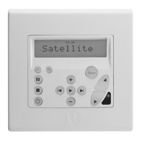
Applications: • Select and control up to eight sources • Controls Up to Eight Sources - The UNO-IR2 controls up to 8 • Elegant design available in white, bone (ivory), brown, black, audio/video sources and a stereo/home theater receiver or and almond colors IR-controlled amplifier. - Page 5 IR RECEIVER - Receives IR remote control sig- nals and passes them to the source equipment. Also used when operating the UNO-IR2 Keypad by using the UNO-LRC1 remote COMMAND KEYS - Pressing the command...
- Page 6 UNO-IR2 Keypad-Button Guide “SYS-ON”- Indicates system on 12-character alpha-numeric display The UNO-IR2 keypad buttons are configured during programming to control the source equipment. Listed above are their typical applications, though most can be customized to work any desired IR function.
- Page 7 VOLUME UP/DOWN - Raises and lowers the volume The optional UNO-LRC1 remote control will operate the UNO-IR2 keypad and all sources it is programmed to control. This requires no programming of the UNO-LRC1 remote control when used with the UNO-IR2. Three additional...
-
Page 8: Keypad Operation
UNO-IR2. Press and release to turn off the are sequentially selected, each source's name appears UNO-IR2 Keypad. This will interrupt the speaker signals in the on the keypad LCD panel. is also used to enter the corresponding room if wired through the keypad relay. - Page 9 “All On” or “All Off” commands. Use The command keys allow control of the selected source at to toggle between Enable or Disable and the UNO-IR2 keypad. The command keys are activated with a to select. Press to exit the User Menu.
-
Page 10: Keypad Installation
• Route the left and right speaker wires from the stereo amplifier to the “Amplifier” modular snap connector on the UNO-IR2. Standard 16- gauge 4-conductor stranded speaker wire can be run up to to 125 feet; 14-gauge wire can be run up to 250 feet. -
Page 11: Os Update
• When using CAT-5 cable, DO NOT connect the Orange/White IR AND POWER CONNECTOR - Connection from UNO-IR2 to and Green/White to GND required connecting block (e.g., 857) (ground) at the UNO-IR2 keypad. - Page 12 INSTALLER Typical Keypad Configuration Typical Keypad Configuration The UNO-IR2 keypad uses an IR connecting block (e.g., Russound 857) for power and for communi- cating with the components and other UNO-IR2 keypads. Sources and the amp/receiver receive communication from the 857 connecting block with 845.1 or...
- Page 13 INSTALLER EZB-1SC Connections Top View EZB-1SC Connection EZB-1SC Details When using shielded 22/4 AW2260AB two-twisted pair cable, use 22/4 WIRE one twisted pair for power COLOR TYPE and ground, and the other twisted pair for status and +V (+12V) IR signal. Always drain the Black shield by connecting it or Green...
-
Page 14: Multiple 857 Connections
INSTALLER Multiple 857 Connections Multiple 857 Connections Multiple arrangements of UNO-IR2 keypads and EZB-1SC connecting blocks may be linked together using the wiring diagram shown to link successive 857 connect- ing blocks. Each connect- ing block must have its own 1201A power supply. - Page 15 NOTE: Do not connect the +12VDC wire between the 857 con- necting blocks. Each 857 requires its own 1201A power supply which will power up to four UNO-IR2 keypads. Only GND, SIGNAL and STATUS need to be connected between multiple connecting blocks.
- Page 16 Russound, Part #2500-120633. SETUP BUTTON - Activates Installer Setup Mode for the UNO-IR2 keypad OS UPDATE/DATA PORT - Port used for UNO-IR2 keypad updates and configuration backup LEARNING IR RECEIVER DIODE - Used for learning remote control commands...
-
Page 17: Programming Overview
This Key Function listing identifies what IR codes are supported for each command type (source) by the built-in library. “Learned Only” indicates that this function is not supported and must be learned into the UNO-IR2. This list of key functions reflects the differ- ent available key functions associated with what you see on the LCD panel when performing the Key Configuration procedure in the Installation Menu. - Page 18 The Source Information Form above has been completed as an example of the types of information used to plan the UNO-IR2 programming. The blank form for actual programming use is found on Page 47. Once the Source Information Form is completed, it will be referred to during the programming process.
-
Page 19: Installation Menu Overview
INSTALLER Installation Menu Overview The Installation Menu provides the step-by-step complete programming procedure for the UNO-IR2 keypad. The Installation Menu is presented in the following pages in the same sequence as it appears in the keypad firmware, which is feature based. However, the following configuration sequence is recommended for initial setup. - Page 20 INSTALLER Installation Menu Navigation There are three item types in the installation menu and are noted as such in the main text. Understanding each type will simplify menu navigation. Menu Item – Acts as a folder that holds procedures and/or feature parameters. Procedure –...
-
Page 21: Source Setup Menu
NOTE: The Amp/Rcvr is configured under the AMP/RCVR Setup on Page 32. However, if the receiver’s tuner is used, it is config- ured as a Source in Source Setup below. Source Setup allows the sources 1-8 on the UNO-IR2 keypad to be configured through the following sub-menu items: BASIC SETUP... -
Page 22: Installation Menu Overview
INSTALLER Installation Menu Press and Source Setup - Basic Setup Procedure Release Setup Button Setup button on right side of keypad under cover plate POWER MACRO AMP/RCVR SOURCE Installation LEARN IR SYSTEM EDITOR SETUP SETUP Procedure Menu Menu Procedure Procedure Menu Menu Source... - Page 23 4. DEVICE CODE – Enter source component code number from the Reference section of the Manual. 5. TEST IR? – If “Yes” is selected, the UNO-IR2 sends a power command to the source component. If “No” is selected, the procedure advances to USE NUM IR? (step 7) 6.
- Page 24 INSTALLER Installation Menu Source Setup - Key Configuration Procedure Press and Release Setup Button Setup button on right side of keypad under cover plate POWER MACRO AMP/RCVR Installation SOURCE LEARN IR SYSTEM EDITOR SETUP SETUP Procedure Menu Menu Procedure Procedure Menu Menu Source...
-
Page 25: Key Configuration Procedure
INSTALLER Installation Menu Press the Setup button to back out to the top of the Basic Setup menu. Press the Next button to move to the Key Config menu. Press the Play button to enter Key Config when displayed. KEY CONFIGURATION PROCEDURE Key Configuration redefines command key (button) functions for each source. - Page 26 INSTALLER Installation Menu Key Config (cont’d) 7. KEY FUNCTION – Select a function for the button. 8. SAVE CHANGES? – Select “Yes” to save changes. Procedure advances to SOURCE NUM (step 1) Press the Setup button to back out to the top of Key Config. Press the Next button to move to Source Names.
-
Page 27: Source Names Flow Chart
INSTALLER Installation Menu SOURCE NAMES PROCEDURE This procedure allows the installer to assign the source names for the sources to be controlled. See Source Names - Flow Chart on Page 26 1. SOURCE NUM – Select the source number this name will be assigned to. 2. - Page 28 INSTALLER Installation Menu Press and Source Setup - Numeric IR Procedure Release Setup Button Setup button on right side of keypad under cover plate POWER MACRO AMP/RCVR SOURCE Installation LEARN IR SYSTEM EDITOR SETUP SETUP Procedure Menu Menu Procedure Procedure Menu Menu Source...
- Page 29 INSTALLER Installation Menu Numeric IR (cont’d) i. LEARNED SRC – Select the learned source bank to be assigned to the source component. Procedure advances to KEY FUNCTION (step 8) b. Selected: Unassigned The numeric IR Prefix command is cleared. Procedure advances to SUFFIX CMD (step 9) c.
- Page 30 INSTALLER Installation Menu Source Setup - Source Select Command Press and Release Setup Button and # of Sources Procedures Setup button on right side of keypad under cover plate POWER MACRO AMP/RCVR Installation SOURCE LEARN IR SYSTEM EDITOR SETUP SETUP Procedure Menu Menu...
- Page 31 INSTALLER Installation Menu Numeric IR (cont’d) i. MACRO ID – Enter the macro ID number. Menu advances to SAVE CHANGES (step 13) e. All Other Selections: Procedure advances to DEVICE CODE (step 11) 11. DEVICE CODE – Source component code for IR control. 12.
-
Page 32: Source Select Command Flow Chart
INSTALLER Installation Menu Src Sel Cmd (cont’d) c. Selected: Default Default selects the same device type and device code previously setup in BASIC SETUP. Procedure advances to KEY FUNCTION (step 4) d. Selected: Macro: (To build macros, see Macro Editor Page 41) i. -
Page 33: Basic Setup Procedure
INSTALLER Installer Menu BASIC SETUP KEY CONFIG Press the Play button to enter BASIC SETUP when displayed. BASIC SETUP PROCEDURE This procedure uses a built-in Amp/Receiver “templates” to quickly and easily configure the settings needed for basic operation of the amp or receiver. Before performing BASIC SETUP, connect the the Amp/Receiver and be sure that all sources are powered on. See AMP/RCVR Basic Setup - Flow Chart below AMP/RCVR Setup - Basic Setup Procedure Press and... - Page 34 2. DEVICE CODE – Enter Amp/Receiver’s code number from the Reference section of the Manual. 3. TEST IR? – If “Yes” is selected, the UNO-IR2 sends a power command to the Amp/Receiver. If “No” is selected, the procedure advances to SAVE CHANGES (step 5) 4.
-
Page 35: Key Configuration Procedure
INSTALLER Installation Menu AMP/RCVR Setup - Key Configuration Procedure Press and Release Setup Button Setup button on right side of keypad under cover plate POWER MACRO AMP/RCVR SOURCE Installation LEARN IR SYSTEM EDITOR SETUP SETUP Procedure Menu Menu Procedure Procedure Menu Menu BASIC... -
Page 36: Power Mgt Procedure
1. USE STATUS? – Asks if the 12VDC trigger status will be used. 2. POWER ON CMD? – Used to power amp/receiver and/or source equipment when any of the UNO-IR2 keypads is turned on. If “No,” procedure advances to POWER OFF CMD (step 6) -
Page 37: Power Management Procedure
INSTALLER Installation Menu Power Management Procedure Press and Release Setup Button Setup button on right side of keypad under cover plate Power POWER MACRO AMP/RCVR SOURCE LEARN IR SYSTEM EDITOR SETUP SETUP Procedure Menu Procedure Procedure Menu Menu Menu STATUS... - Page 38 INSTALLER Installation Menu POWER MGT PROCEDURE (cont’d) 3. COMMAND TYPE – Select the type of Amp/Receiver or source command (e.g., Tuner/Amp, CD, TV, etc.). a. Selected: Learned IR Choose Learned IR if the pre-programmed IR code library does not support the Amp/Receiver or source component.
- Page 39 This procedure allows IR commands to be learned into the keypad for future assignment. NOTE: IR codes must be learned in using a remote aimed at the UNO-IR2’s IR receiver diode. There are nine locations to store learned IR commands: one for each of eight sources and one for the Amp/Receiver.
-
Page 40: Learn Ir
Setup button on right side of keypad under cover plate Learn POWER MACRO AMP/RCVR SOURCE LEARN IR SYSTEM EDITOR SETUP SETUP Procedure Menu Procedure Procedure Menu Menu Menu Red LED on right side of UNO-IR2 blinks rapidly Transmit IR remote into UNO-IR2 receiver diode... -
Page 41: Macro Editor Procedure
INSTALLER Installation Menu Learn IR (cont’d) 5. SUCCESS? – Asks if the IR test was a success IF YES - If the test was a success, specify “Yes” and proceed to KEY FUNCTION (step 2) IF NO - If the test was a failure, specify “No” and LEARN/DELETE (step 3) reappears on the display allowing another code to be learned in. -
Page 42: Macro Editor Procedure
INSTALLER Installation Menu Macro Editor Procedure Press and Release Setup Button Setup button on right side of keypad under cover plate Macro POWER MACRO AMP/RCVR SOURCE LEARN IR SYSTEM EDITOR Editor SETUP SETUP Procedure Menu Procedure Procedure Menu Menu Menu... -
Page 43: Keypad Id Procedure
INSTALLER Installation Menu Macro Editor (cont’d) d. Selected: Macro: See Macro Editor Page 41) i. MACRO ID – Enter the macro ID number. Menu advances to COMMAND NUM (step 3) e. Selected: Delay Enter a 1- to 60-second delay time to postpone delivery of the next command in the macro. Procedure advances to COMMAND NUM (step 3) f. -
Page 44: Copy Config
KEYPAD DIAGNOSTICS INFO INIT FIRMWARE CONFIG Procedure Menu Procedure Procedure Procedure Procedure Procedure COPY HOLD BUTTON TO... PLAY TEST This Procedure returns the UNO-IR2 START ARE YOU DISP to its SURE? UPDATE BLOCK Factory settings COLOR LOOKING FOR... SENDING DATA... - Page 45 The green light on the right side of the keypad flashes to show traffic. Once the copy procedure for the first keypad is complete, DATA RECEIVED appears on its display. SYSTEM INFO PROCEDURE System Info allows the installer to view the UNO-IR2’s manufacturing build properties. See System Menu - Flow Chart on Page 44 BUILD TIME...
-
Page 46: Factory Initialization
Update Firmware allows the installer to update the UNO-IR2’s firmware using a Russound programming cable (P/N 2500-120633) connected to the OS update data port on the side of the UNO-IR2 keypad. Updates are made available with associated procedures in the Document Center at www.russound.com. See System Menu - Flow Chart on Page 44 1. -
Page 47: Source Information Form
REFERENCE Source Information Form Source Information Form AMP/RCVR UNO-IR2 Amp/Rcvr Source Input # Source Name Manufacturer Model # IR Command Type IR Device Code (4-digit or Learned Source #) Numeric IR Y or N Y or N Y or N... -
Page 48: Source Names
REFERENCE Source Names Satellite DVD Player 3 Classical VCR 2 Front Door Satellite 1 AUX 1 Computer Source 1 Internet Radio Satellite 2 AUX 2 Country Source 2 Jazz Satellite 3 Blues Dance Music Source 3 Special Laser Disk Cable Digital Cable Source 4 Tape... - Page 49 REFERENCE Command Type IR Device Codes Device Codes for TVs: Electroband 0000 0179, 0056, 0016 Emerson 0154, 0236, 0463, 0180, 0178, Midland 0047, 0747, 0017, 0051 0179, 0019, 0623 Minutz 0021 0030, 0019 Envision 0030 Mitsubishi 0093, 0150, 0178, 0019 Admiral 0093, 0463 Fisher...
- Page 50 REFERENCE Command Type IR Device Codes Sansui 0463 Pioneer 1010 Device Codes for Cable: Sanyo 0154 Princeton 0113, 0295 0003, 0008, 0014, 0017 Scimitsu 0019 Samsung 1190, 1204 Americast 0899 Scotch 0178 Sensory Science 1126 Bell & Howell 0014 Scott 0236, 0180, 0178, 0179, 0019 Sharp 1010...
- Page 51 REFERENCE Command Type IR Device Codes Gradiente 0000 Panasonic 0035, 0225, 0162, 1062, Device Codes for VCRs: 1035,1162, 1262, 0454, 0616 HI-Q 0047 Penney 0035, 0037, 0042, 0240, 0038, Admiral 0048, 0209 Harley Davidson 0000 1035, 1237 Adventura 0000 Harman/Kardon 0081, 0038 Pentax 0042...
- Page 52 REFERENCE Command Type IR Device Codes Technics 0035, 0162 Device Codes for DVD Players: Sanyo 0670 Teknika 0035, 0037, 0000 Sharp 0630 Aiwa 0641 Thomas 0000 Sherwood 0633 Apex Digital 0672, 0755, 0794, 0795, 0796, Tivo 0618, 0636 Sony 0533, 1533 0797, 0830 Toshiba 0045, 0043, 0845...
- Page 53 REFERENCE Command Type IR Device Codes Sansui 1089 0000 Sonic Frontiers 0157 Sherwood 1653 DMX Electronics 0157 Sony 0490, 0000, 0100 Sony 1058, 1158, 1258, 0158 Denon 0873 1208 Stereophonics 1023 Emerson 0305 Technics 0029 Sunfire 1313 Fisher 0179 Victor 0072 Technics 1308, 1309, 1518, 0039...
- Page 54 REFERENCE Key Functions-Command Types KEY FUNCTION CABLE VIDEO ACCESSORY SAT/DSS Power On/Off POWER Power On/Off Power On/Off Power On/Off On, Power On/Off On, Power On/Off On, Power On/Off On, Power On/Off Off, Power On/Off Off, Power On/Off Off, Power On/Off Off, Power On/Off Channel Up Channel Up...
- Page 55 REFERENCE Key Functions-Command Types KEY FUNCTION CABLE VIDEO ACCESSORY SAT/DSS Menu Up, Adjust Up MENU UP Menu Up Menu Up Menu Up Menu Down, Adjust Dn MENU DOWN Menu Down Menu Down Menu Down Menu Left MENU LEFT Menu Left Menu Left Menu Left Menu Right...
- Page 56 REFERENCE Key Functions-Command Types LASER DISK TUNER/AMP KEY FUNCTION POWER Power On/Off Power On/Off Power On/Off Power On/Off On, Power On/Off On, Power On/Off On, Power On/Off On, Power On/Off Off, Power On/Off Off, Power On/Off Off, Power On/Off Off, Power On/Off CHANNEL UP Channel Up Learned Only...
- Page 57 REFERENCE Key Functions-Command Types KEY FUNCTION TUNER/AMP LASER DISK BACK Last Channel Learned Only Clear Clear MENU UP TV/VCR Menu Up Menu Up Menu Up, Adjust Up MENU DOWN Input Select Menu Down Menu Down Menu Down, Adjust Down MENU LEFT Play Menu Left Menu Left...
- Page 58 REFERENCE Key Functions-Command Types KEY FUNCTION AMP/MISC. AUDIO HOME CONTROL POWER Power On/Off Power On/Off Power On/Off On, Power On/Off On, Power On/Off On, Power On/Off Off, Power On/Off Off, Power On/Off Off, Power On/Off CHANNEL UP Preset Up Learned Only Bright, Raise, Up CHANNEL DOWN Preset Down...
- Page 59 REFERENCE Key Functions-Command Types KEY FUNCTION AMP/MISC. AUDIO HOME CONTROL BACK Clear Track, Clear Learned Only MENU UP Menu Up, Adjust Up Menu Up Menu Up, Mode MENU DOWN Menu Down, Adjust Down Menu Down Menu Down, Timer MENU LEFT Menu Left Menu Left Menu Left, Oscillate...
-
Page 60: Technical Specifications
TECHNICAL SPECIFICATIONS Certifications Technical Specifications Dimensions: 3.65"W x 1.75"D x 4.3"H (9.2 x 10.9 x 2.8 cm) Fits 2 Gang UL/CSA Approved 36ci Junction Box Weight: 9 oz. (255 g) Power Requirements: 12 VDC 200mA Speaker Relay: 100W music power max, 30W RMS continuous per channel... -
Page 61: Warranty Repair
Damage to or destruction of components due to application of excessive power voids the warranty on those parts. In these cases, repairs will be made on the basis or the retail value of the parts and labor. To return for repairs, the unit must be shipped to Russound at the owner's expense, along with a note explaining the nature of service required. - Page 62 NOTES...
- Page 63 NOTES...
- Page 64 Russound 5 Forbes Road, Newmarket, NH 03857 tel 603.659.5170 • fax 603.659.5388 e-mail: tech@russound.com www.russound.com 28-1151...
Need help?
Do you have a question about the UNO-IR2 and is the answer not in the manual?
Questions and answers