Table of Contents
Advertisement
Quick Links
Thank you for purchasing this Esco Laminar Flow
Cabinet. Please read this manual thoroughly to
familiarize yourself with the many unique
features and exciting innovations we have built
into your new equipment.
Esco Lifesciences provides many other resources
at www.escolifesciences.com and www.esco-
medical.com, to complement this manual and
help you enjoy many years of productive and safe
use of Esco Products.
User Manual
For Technical Service, contact
NORTH AMERICA
Esco Technologies, Inc.
903 Sheehy Drive, Suite F, Horsham, PA 19044, USA
MIRI® Laminar Flow
Tel 215 441 9661
eti.sales@escolifesciences.com
•
REST OF THE WORLD
Cabinet
Esco Micro Pte. Ltd.
21 Changi South Street 1
•
Singapore 486 777
Tel +65 6542 0833 • mail@escolifesciences.com
Laminar Flow Cabinet
www.escolifesciences.com
Esco MIRI® Laminar Flow Cabinet
User Manual | Version A.1 – Released August 2023
Advertisement
Table of Contents

Related Manuals for Esco MIRI MLF-3D8


Summary of Contents for Esco MIRI MLF-3D8
- Page 1 Thank you for purchasing this Esco Laminar Flow Cabinet. Please read this manual thoroughly to familiarize yourself with the many unique features and exciting innovations we have built into your new equipment. Esco Lifesciences provides many other resources at www.escolifesciences.com and www.esco- medical.com, to complement this manual and...
-
Page 2: Copyright Information
Esco makes no representations or warranties as to the accuracy of the information contained in this manual. In no event shall Esco be held liable for any damages, direct or consequential, arising out of or related to the use of this manual.”... -
Page 3: Table Of Contents
Table of Contents Warranty Terms and Conditions ......................6 Introduction ..............................8 Safety Warning ..........................8 Document Management ........................8 Limitation of Liability ........................8 European Union Directive on WEEE and RoHS ................8 Symbols .............................. 9 MIRI Laminar Flow Cabinet ........................12 ®... - Page 4 Post Purge Time........................... 30 Data Log Period ........................... 30 Setting Mode ..........................31 Normal Mode ..........................31 Maintenance Mode ........................31 Field Calibration .......................... 32 Airflow Calibration ........................32 Reset Calibration ......................... 32 Admin Settings ..........................32 New ADMIN PIN (Default 0009) ....................32 New FAN PIN (Default 0000 - DISABLED) ................
- Page 5 Calibrating the Airflow Set Point ....................47 How to set the Standby Mode Airflow ................... 48 HEPA/ULPA Filter PAO Leak Test ....................48 Particle Count Test .......................... 49 Noise Level Test (Optional for field testing) ................. 50 Light Intensity Test (Optional for field testing) ................51 MIRI Laminar Flow Cabinet ®...
-
Page 6: Warranty Terms And Conditions
Esco that these parts were defective at the time of being sold, and that all defective parts shall be returned, properly identified with a Return Authorization. - Page 7 Note: The warranty periods for MLF may vary by country. Contact your local distributor for specific warranty details. The warranty period starts two months from the date your equipment is shipped from Esco facility for international distributors. This allows shipping time so the warranty will go into effect at approximately the same time the equipment is delivered to the user.
-
Page 8: Introduction
The disposal and/or emission of substances used in connection with this equipment may be governed by various local regulations. Familiarization and compliance with any such regulations are the sole responsibility of the users. Esco’s liability is limited with respect to user compliance with such regulations. -
Page 9: Symbols
Electronic Equipment (WEEE) Directive 2002/96/EC. It is marked with the following symbol: Esco sells products through distributors throughout Europe. Contact your local Esco distributor for recycling/disposal. Recommended method of disposal is according to The Federal, State, and Local Government regulations. -
Page 10: Declaration Of Conformity
6100-4-11: 2004 + A1: 2017; IEC 61010-1: 2010/AMD 1:2016 More information may be obtained from Esco Lifesciences’s authorized distributors located within the European Union. A list of these parties and their contact information is available on request from Esco. Place of Issue: Singapore... - Page 11 : IEC 61010-1:2010 + AMD 1:2016 (3.1 edition) : EN 60601-1-2:2015 + A1:2021 More information may be obtained from Esco Lifesciences’s authorized distributors located within the European Union. A list of these parties and their contact information is available on request from Esco.
-
Page 12: Miri ® Laminar Flow Cabinet
MIRI Laminar Flow Cabinet ® About the Product The MIRI Laminar Flow cabinet provides a controlled and clean environment inside a ® laboratory. It employs a vertically unidirectional clean air pattern which supplies the working zone with higher quality of air therefore, preventing the sample from being risked to contamination. -
Page 13: About The Laminar Flow
About the Laminar Flow MIRI Laminar Flow cabinet is classified as a laminar flow cabinet which provides a controlled ® and clean environment inside the laboratory. The specific type of laminar flow pattern applied in the MIRI Laminar Flow is the unidirectionally vertical pattern. The vertical airflow pattern provides clean air towards the working surface of the workstation;... -
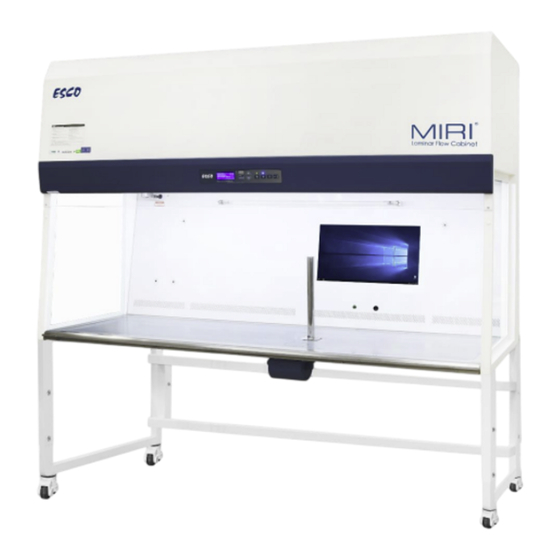
Page 14: Quick View Of The Miri ® Laminar Flow Cabinet
Quick View of the MIRI Laminar Flow Cabinet ® Figure 2. Simple mechanical drawing of the MLF 1. Pre-filter 2. Main ULPA filter 3. Donut-shaped airflow sensor 4. LED light 5. UV light 6. Transparent tempered glass side panels 7. Spill-retaining stainless-steel worktop 8. -
Page 15: Installation
Installation Location Requirements MIRI Laminar Flow Cabinet is a stationary device, meaning that the equipment, once installed ® and placed into service, is not intended to be moved from one place to another place. The unit is meant to remain in the same location within a laboratory/institution. The operating environment requirement for the MLF cabinet is mentioned in this user manual, in below section. -
Page 16: Operating Environment Requirements
Telescoping height with Castor Wheel o Telescoping height with Levelling Feet Esco support stands with levelling feet is recommended for safety. It is recommended that the installation of the support stand be carried out by qualified personnel (contact your Esco Distributor for assistance). -
Page 17: Electrical Requirements
Electrical Requirements ▪ The MIRI Laminar Flow Cabinet should always be connected to its own dedicated ® power outlet. The power rating for all MLF models is shown in the table below. Ensure that the outlet ▪ is rated accordingly. Table 1. -
Page 18: Connecting The Electrical Supply
Connecting the Electrical Supply • Please refer to the serial label on the MLF cabinet for the proper electrical rating to ensure that the cabinet is connected to the correct electrical supply. • Connect the supplied power cord provided in the input on the top of the MLF. Make sure that the cable connector is seated firmly in the socket. - Page 19 3. Remove the 4 bolts as shown in the below image. Figure 5. 4 bolts in the MIRI Laminar Flow Cabinet 4. Lower the cabinet slowly and carefully onto the support stand. Ensure the support stand is aligned correctly with the cabinet. 5.
-
Page 20: Transport And Disposal
7. Pull out the metal pallet. The installation has been completed. Figure 8. Metal pallet in the MIRI Laminar Flow Cabinet Transport and Disposal Transport The devices are packed in a carton box, and it is wrapped in a polyethylene. The box is affixed to a pallet with special straps. - Page 21 Description Image 1. Manufacturer’s address and country of origin 2. CE Mark 3. Model 4. Serial Number 5. Voltage rating 6. Maximum power 7. Full-Load-Amps Value 8. Observe WEEE Disposal It is highly recommended that prior to proper disposal, all surfaces of the cabinet to be disinfected or decontaminated.
-
Page 22: Basic Cabinet Instructions
Basic Cabinet Instructions Cleaning Instructions MIRI Laminar Flow Cabinet is not a sterile device. It is not delivered sterile state and it is not ® possible to keep them sterile while in use. However, their design was created with great care to make it easy for the user to keep the device sufficiently clean and not contaminate the key components. -
Page 23: Uv Lamps For Working Zone Decontamination (Optional)
Therefore, you should pay careful attention to the following guidelines in order to achieve comfortable and healthy working conditions: Always ensure that your legs have enough legroom. • • Keep your lower back comfortably supported by your chair. Adjust the chair or use a pillow behind your back whenever necessary. -
Page 24: All-In-One (Aio) Pc (Optional)
(UV timer is disabled by default). Leaving the UV lamp on for over 60 minutes or even overnight is not recommended because it shortens the lifespan of the lamp. The UV lamps used in Esco cabinet have a lifespan of 2,000 hours. - Page 25 To turn on the Monitor Ensure that the power plug has been connected to the cabinet and the power socket (indicated when the Sentinel™ Gold is turned on). 2. After the first step has been completed, proceed to press the On/Off button located below the monitor to turn it on.
-
Page 26: Sentinel™ Gold Microprocessor Controller System
Sentinel™ Gold Microprocessor Controller System Fan Button Turns the fan on or off. To activate standby mode. Lamp Button Turns the LED lamp on or off. Socket Button Turns on or off the electrical socket (if present). The maximum rating of all the outlets in the cabinet is 5 A. If there is an overload, the fuse will blow. -
Page 27: Menu Options
Menu Options Please refer to the following diagram for complete reference to all menu options available. NEW ADMIN PIN NEW ADMIN PIN RESET B/H/M RESET UV/H/M NEW ADMIN PIN RESET F/H/M NEW ADMIN PIN RESET DEFAULT AIRFLOW OUT TEMP NEW ADMIN PIN NEW ADMIN PIN NEW ADMIN PIN MIRI... -
Page 28: Settings
UV timer can be used to switch off the UV lamp automatically after a fixed period. The UV timer can be set up to 24 hours. By default, the timer is set to 60 minutes. Esco does not recommend leaving the UV lamp on for more than 60 minutes per decontamination cycle as it shortens the lifespan of the UV lamp. -
Page 29: Experiment Timer
Experiment Timer Experiment timer is a countdown timer that can be used for critical experiment. Experiment timer can be set between “00:00:00” and “17:59:59”. To set the Experiment Timer: 1. Press the MENU button to enter menu display – if the cabinet is secured by a FAN PIN, then it will ask for the PIN, otherwise go to step 3 2. -
Page 30: Post Purge Time
During the warmup period, the user can use the FAN button to turn off the blower, LIGHT button to turn on and off the fluorescent lamp and MENU button. However, to be able to access the menu, the user needs to input ADMIN PIN and even then, some sections of the menu (WARM UP and all FIELD CALIBRATION) are still not accessible for the user. -
Page 31: Setting Mode
To Set Data Log Period 1. Press MENU button to enter the menu display – if the LFC is secured by a FAN PIN, then it will ask for the PIN, otherwise go to step 3. 2. Use UP/DOWN button to enter the FAN PIN or ADMIN PIN digit by digit. Press SET button to confirm. -
Page 32: Field Calibration
Field Calibration The purpose of calibration is to ensure the accuracy of the airflow display and alarm (if present). This involves measuring airflow with reference instrumentation and establishing reference between airflow sensor(s) on the LFC to the standard reference. Calibration should only be carried out by qualified personnel. -
Page 33: New Fan Pin (Default 0000 - Disabled)
New FAN PIN (Default 0000 - DISABLED) FAN PIN restricts access to fan control and some parts of the menu, settings and set mode. User must enter the four-digit PIN before switching the fan on or off. This feature prevents unauthorized personnel from accessing critical control sections. -
Page 34: Filter Life Display
To Set A/F Monitor: 1. Press MENU button to enter the menu display – if the LFC is secured by an ADMIN PIN, then it will ask for the PIN, otherwise go to step 3. 2. Use UP/DOWN button to enter the ADMIN PIN digit by digit. Press SET button to confirm. -
Page 35: Uv Interlock
MIRI Laminar Flow Cabinet comes with English as the default language; however, other languages are also available for a more diverse option for our customer, the languages available include Italian, Spanish, and French. To Set Language: 1. Press MENU button to enter the menu display – if the LFC is secured by a FAN PIN, then it will ask for the PIN, otherwise go to step 3. -
Page 36: Reset Uv/H/M (If Uv Is Present)
To Reset B/H/M: 1. Press MENU button to enter the menu display – if the LFC is secured by an ADMIN PIN, then it will ask for the PIN, otherwise go to step 3. 2. Use UP/DOWN button to enter the ADMIN PIN digit by digit. Press SET button to confirm. -
Page 37: Reset Default
To Reset F/H/M: 1. Press MENU button to enter the menu display – if the LFC is secured by an ADMIN PIN, then it will ask for the PIN, otherwise go to step 3. 2. Use UP/DOWN button to enter the ADMIN PIN digit by digit. Press SET button to confirm. -
Page 38: Alarm Mute Duration
To Set Airflow Out Temp: 1. Press MENU button to enter the menu display – if the LFC is secured by an ADMIN PIN, then it will ask for the PIN, otherwise go to step 3. 2. Use UP/DOWN button to enter the ADMIN PIN digit by digit. Press SET button to confirm. -
Page 39: Standby Mode
• If the message "Call Service for re-certification" is displayed, it means that the LFC certification has expired. Call service or Esco's local distributor for re-certification. Diagnostic Mode Diagnostic mode can be accessed by pressing the SET button. The diagnostic mode allows the user to know the condition of the LFC or help the service engineer during maintenance and troubleshooting. - Page 40 seconds. ADC AFF ADC for Fail Point Airflow – calculated using offset based on Airflow Nominal Point. ADC AFN ADC for Nominal Point Airflow – based on field calibration. ADC AFA ADC for Actual Airflow – showing real time sensor reading. ADC AF0 ADC for factory calibrated Zero Point Airflow (no airflow).
-
Page 41: Maintenance
Proper and timely maintenance is crucial for a trouble-free operation of any device and your Esco cabinet is no exception to this rule. We strongly recommend that you follow the maintenance schedule suggested hereunder to obtain optimal performance from your Esco cabinet. -
Page 42: Product Specification
Filter Efficiency HEPA/ULPA filtration with 99.9995% efficiency ISO Classification ISO Class 3 Noise Level Reading* ≤48 dB(A) Control System Esco Sentinel™ Gold Microprocessor Controller Microscope Pole Provision Position for 1 microscope Transmitted Light Source 1 set Advanced Option 21” Touchscreen Monitor**... -
Page 43: Electromagnetic Compatibility
Electromagnetic Compatibility Table 6 Electromagnetic emissions Emission Test Compliance Electromagnetic Environment Guidance RF Emissions CISPR 11 Group 1 The MIRI Laminar Flow ® Cabinet does not use RF energy. Therefore, its RF emissions are very low and are not likely to cause any interference in nearby electronic equipment RF Emissions CISPR 11... - Page 44 Power Frequency Power frequency Magnetic Field Side/Axis X, Y, Z Side/Axis X, Y, Z magnetic fields should Immunity Test level at 30 A/m 50 Test level at 30 A/m 50 be at levels IEC 61000-4-8 Hz and 60 Hz Hz and 60 Hz characteristic of a specific location in a typical commercial or...
-
Page 45: Miri Laminar Flow Certification Procedures
“Maintenance Mode”. In the maintenance mode, all alarm functions are defeated. How to set the Cabinet to Maintenance Mode 1. On the Sentinel Gold LCD, at normal mode will display ESCO MLFC XX: XX ESCO MLFC XX: XX Airflow: 0.45 m/s... -
Page 46: Locating The Speed Controller
Locating the Speed Controller Prior to certification, the user would need to be able to locate the speed controller in order to change the blower motor speed. 1. Remove the pre-filter on top of the cabinet 2. The speed control is located on electrical panel below the mesh guard 3. -
Page 47: Fail Airflow Velocity Measurement
Acceptance: 0.45 ± 0.025 m/s Average Velocity _______________ m/s (90 ± 5 fpm) Maximum Deviation _______________ % Acceptance: 20% Result (circle one) Pass / Fail Motor Duty Cycle _______________ % Fail Airflow Velocity Measurement Using the same grid instructions above, measure the fail airflow velocity and fill in the table according to the measurement taken: Acceptance: 0.30 ±... -
Page 48: How To Set The Standby Mode Airflow
Action LCD Display Wait for 3 minutes for the software to record this sensor ADC point. CALIBRATION 17:23 Do not change Motor Duty Cycle or disrupt airflow / sensor during Wait 03Min this time. Time Left: 02:59 Calibration Done message will be displayed, and the screen will go CALIBRATION 17:26 back to MENU OPTIONS shown in Step 2. -
Page 49: Particle Count Test
Cabinet Model MLF-A 3 feet 4 feet 5 feet 6 feet Total Airflow (cfm) 1064 4. With traverse speed of 2 inches/second, scan the airflow filter media for leakage and record the results, Airflow Filter Leaks detected in media Yes / No Leaks detected in gasket Yes / No Particle penetration... -
Page 50: Noise Level Test (Optional For Field Testing)
Cabinet Models MLF-A 3 feet 4 feet 5 feet 6 feet Width = w (mm) (in) 914 (36) 1219 (48) 1524 (60) 1829 (72) Height/Depth = h (mm) (in) 610 (24) 610 (24) 610 (24) 610 (24) Distance from diffuser perimeter 300 (11.8) 300 (11.8) 300 (11.8) -
Page 51: Light Intensity Test (Optional For Field Testing)
Testing was performed in accordance with the following IEST (Institute of Environmental Sciences and Technology) contamination control document: IEST-RP-CC002.2 “Recommended Practice for Uni- directional Flow Clean Air Devices” Section 6.11 Light Intensity Test (Optional for field testing) A light intensity meter will be used to measure the light intensity from front to back at the centre line of the working surface of the cabinet. - Page 52 APPENDIX MIRI Laminar Flow Cabinet ®...
-
Page 53: Appendix A: Log Record
APPENDIX A: LOG RECORD Cabinet Model : __________________________________________________________ Serial Number : __________________________________________________________ Person in-charge : __________________________________________________________ 1. This log record should be used by the operator to record any new agent/virus/bacteria/protist that has been introduced to the unit during its operation, problems encountered, etc.
Need help?
Do you have a question about the MIRI MLF-3D8 and is the answer not in the manual?
Questions and answers