Table of Contents
Advertisement
Thank you for purchasing this Esco Biological Safety Cabinet.
Please read this manual thoroughly to familiarize yourself with the
many unique features and exciting innovations we have built into
your new equipment. Esco provides many other resources at our
website, www.escoglobal.com, to complement this manual and
help you enjoy many years of productive and safe use of your Esco
products.
For Technical Service, contact
North America
Esco Technologies, Inc.
2940 Turnpike Drive, Units 15-16 •Hatboro, PA 19040, USA
Toll-Free USA and Canada 1-877-479-3726
Tel 215-441-9661 • Fax 215-441-9660
us.escoglobal.com • usa@escoglobal.com
Rest of the World
Esco Micro Pte. Ltd.
21 Changi South Street 1 • Singapore 486777
Tel +65 6542 0833 • Fax +65 6542 6920
www.escoglobal.com • mail@escoglobal.com
Esco Airstream Class (AC2 - E/S/D/G/N) II BSC User and Service Manual
Version F - Released July 2013
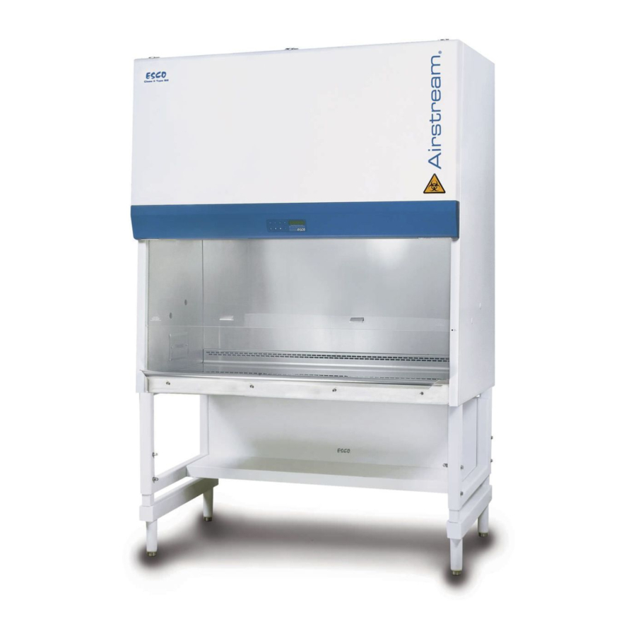
User and Service
Manual
Class II
Biological Safety Cabinet
Advertisement
Table of Contents

Subscribe to Our Youtube Channel
Related Manuals for Esco Class II


Summary of Contents for Esco Class II
- Page 1 Esco provides many other resources at our website, www.escoglobal.com, to complement this manual and help you enjoy many years of productive and safe use of your Esco products. User and Service...
- Page 2 Esco makes no representations or warranties as to the accuracy of the information contained in this manual. In no event shall Esco be held liable for any damages, direct or consequential, arising out of or related to the use of this manual.”...
-
Page 3: Table Of Contents
5.3.1 Setting Cabinet in Maintenance Mode 5.3.2 Adjusting Airflow 5.4 Parts Replacement 5.4.1 Filter Replacement Procedure 5.4.2 Blower Replacement Procedure 5.4.3 Fluorescent Lamp(s) Replacement Procedure 5.4.4 UV Lamp Replacement Procedure 5.4.5 Airflow Sensor Replacement Procedure Class II Biological Safety Cabinet... - Page 4 Chapter 6 - Decontamination 6.1 Decontamination Agents 6.1.1 Formalin/Paraformaldehyde Decontamination 6.1.2 Chlorine Dioxide Decontamination 6.1.3 Hydrogen Peroxide Decontamination 6.2 Recommended Decontamination Sealing Method Chapter 7 - Troubleshooting 7.1 Electrical and Mechanical Troubleshooting 7.2 Software Troubleshooting Chapter 8 - Engineering Details 8.1 AC2-_E_ Engineering Drawing 8.2 AC2-_S_ Engineering Drawing 8.3 AC2-_E_ and AC2-_S_ General Specifications...
-
Page 5: Warranty Terms And Conditions
Esco, were defective at the time of being sold and that all defective parts shall be returned, properly identified with a Return Authorization. - Page 6 MORE THAN THE AMOUNT YOU PAID FOR THE PRODUCT THAT IS THE SUBJECT OF A CLAIM. THIS IS THE MAXIMUM AMOUNT FOR WHICH ESCO IS RESPONSIBLE. These Terms and Conditions shall be governed by and construed in accordance with the laws of Singapore and shall be subject to the exclusive jurisdiction of the courts of Singapore.
-
Page 7: Introduction
The disposal and / or emission of substances used in connection with this equipment may be governed by various local regulations. Familiarization and compliance with any such regulations are the sole responsibility of the users. Esco’s liability is limited with respect to user compliance with such regulations. Class II Biological Safety Cabinet... -
Page 8: European Union Directives On Weee And Rohs
This product is required to comply with the European Union’s Waste Electrical & Electronic Equipment (WEEE) Directive 2002/96/EC. It is marked with the following symbol: Esco sells products through distributors throughout Europe. Contact your local Esco distributor for recycling/disposal. • Directive 2002/95/EC on Restriction on the use of Hazardous Substances (RoHS) - Page 9 Design/ Performance Criteria : EN 12469 (2000) Class II Biological Safety Cabinet More information may be obtained from Esco’s authorized distributors located within the European Union. A list of these parties and their contact information is available on request from Esco...
- Page 10 Design/ Performance Criteria : EN 12469 (2000) Class II Biological Safety Cabinet More information may be obtained from Esco’s authorized distributors located within the European Union. A list of these parties and their contact information is available on request from Esco...
-
Page 11: Chapter 1 - Product Information
Sentinel Gold Control System 18. Stainless Steel Armrest 13. Fluorescent Lamps Sash Window 19. ECM Blower 14. Side Window Sash Handle 20. Downflow ULPA Filter Work tray 21. UV Lamp 22. Paper Catch (optional pre-filter) Class II Biological Safety Cabinet... -
Page 12: Chapter 2 - Sentinel Control System
Chapter 2 - Sentinel Control System 2.1. Sentinel Control System Menu Socket Display Button Button Button Button Set/Mute/ Down Visual Lamp UV/Gas Button Diagnostic Button Alarm Button Button Figure 2.1. Sentinel Gold general parts. 1. Fan Button Turns on and turns off the fan. Activate Standby mode 2. -
Page 13: Menu Options
2.2. Menu Options Please refer to the following diagram for complete reference to all menu options available. ≤ ≤ ≤ ≤ ≤ ≤ ≤ ≤ ≤ ≤ ≤ ≤ ≤ ≤ ≤ ≤ ≤ ≤ Class II Biological Safety Cabinets... -
Page 14: Settings
UV timer can be used to switch off the UV lamp automatically after a fixed period. The UV timer can be set up to 18 hours. By default, the timer is set to 60 minutes. Esco does not recommend leaving the UV lamp on for more than 60 minutes per decontamination cycle as it shortens the lifespan of the UV lamp. -
Page 15: Setting Mode
BSC to the standard reference. Calibration should only be carried out by qualified personnel. This section presents a brief overview of the calibration menu function. For more information, refer to test report. Class II Biological Safety Cabinets... -
Page 16: Admin Settings
2.2.3.1. Airflow Calibration This option allows proper calibration and operation of the airflow sensor alarm. There will be two points to be calibrated, namely inflow fail point and inflow nominal point. 2.2.3.2. Reset Calibration This option allows the user to reset all values calibrated in the field and return it to the values obtained during factory calibration. - Page 17 Using this option, the user can select whether or not to display the airflow when the ambient temperature is out of the optimum temperature range, below 18 C (65 F) or above 30 C (86 Class II Biological Safety Cabinets...
-
Page 18: Stopwatch And Experiment Timer (Only For Non-Motorized Sash Bsc)
2.1.4.11. Alarm Mute Duration To mute unsafe sash height and airfail alarm for a certain period. The mute period can be set from 0 up to 299 seconds; the default value is 30 seconds. Alarm will be activated when sash is not in the working height and when the inflow velocity is below the value prescribed by the standard the cabinet is designed or certified to. -
Page 19: Diagnostic Mode
Note: If the message "Call Service for re-certification" is displayed, it means the BSC certification has expired. Call service or Esco's local distributor for re-certification. 2.5. Diagnostic Mode Diagnostic mode can be accessed by pressing the SET button. The diagnostic mode allows the user to know the condition of the BSC or help the service engineer during maintenance and troubleshooting. -
Page 20: Standby Mode (Half Speed)
2.6. Standby Mode (Half Speed) In Standby Mode, the blower speed is greatly reduced resulting in less power consumption. This mode is typically used during the night to maintain basic level of containment where the cabinet is not used by the operator. -
Page 21: Chapter 3 - Basic Cabinet Operation
When the sash is fully closed, pressing the up button and holding it will prompt the user to input the password to turn on the fan. If the password is correct, the fan will turn on if it was on and the sash will move up to the Safe Height setting and stop. Class II Biological Safety Cabinets... -
Page 22: Using Sash Window
Raise Sash from Safe Height Position When the sash is in safe operation position, pressing the up button and holding it will cause the sash to move up to the fully open position and stop. If the fluorescent lights are on as the sash rises, they will stay on as long as the sash is allowed to fully open. -
Page 23: Working Ergonomics
There is a potential risk of being constrained in the same posture for a long time. • Sitting position is one of the most stressful postures for one’s back. • Therefore, you should pay careful attention to the following guidelines in order to achieve comfortable and healthy working conditions: Class II Biological Safety Cabinets... -
Page 24: Uv Lamps (If Present)
3.5. UV Lamps (If Present) Shortwave UV (UVC) is considered as germicidal and virucidal. The UV lamp that Esco provides has a large portion of the spectrum in the UVC range. Unlike many other types of decontamination agent, UV light does not leave any residue. -
Page 25: Gaseous Decontamination
Periodically and as mandated by your risk assessment • 3.8. Further Information Guide Biosafety Biological Safety Cabinets downloaded from • http://escoglobal.com/resource.php?id=13 An educational video on “Working Safely in your Biological Safety Cabinet” is available for viewing at • http://www.youtube.com/watch?v=ZnUW1N-JJz8 Class II Biological Safety Cabinets... -
Page 27: Chapter 4 - Maintenance
Chapter 4 - Maintenance 4.1. Scheduled Maintenance Proper and timely maintenance is crucial for trouble-free functioning of any device and your Esco BSC is no exception to this rule. We strongly recommend that you follow the maintenance schedule suggested hereunder in order to obtain optimal performance from your Esco BSC. - Page 28 Accessing the paper catch The purpose of accessing the paper catch is to remove any retained materials that might cause obstructions to airflow. Care must be taken as the area is contaminated. Figure 4.1. Paper catch access. Pre-filter Installation: 1. Insert the pre-filter to the opening of the paper catch as shown in image 1 above. 2.
-
Page 29: Maintenance/Service Log
4. Tilt up the sash glass freely for cleaning. 4.2. Maintenance/Service Log It is good practice (and in some cases regulatory requirement) to maintain a log of all maintenance work carried out on your cabinet. Class II Biological Safety Cabinets... -
Page 30: Chapter 5 - Maintenance And Re-Certification Of The Cabinet
Esco products generally provide years of trouble-free operation however like all equipment they require maintenance and service. Maintenance and service should be carried out by trained personnel. Esco offers training courses to equip service providers with the latest skills, information and tools to successfully maintain and service Esco products. -
Page 31: Cabinet Field Certification
Press SET with 0000 last digit flashing Press ▼button to key in 9 Press SET 3. Alarm will sound, wait until alarm stops. Cabinet should read. MENU OPTIONS XX:XX → SETTINGS SET MODE FIELD CALIB ADMIN SETTINGS Class II Biological Safety Cabinets... -
Page 32: Adjusting Airflow
4. Use the ▼ button until the LCD displays SET MODE. Press the SET button and LCD would show : MENU OPTIONS XX:XX → NORMAL MODE QUICKSTART MODE MAINTENANCE MODE ▼ 5. Use the bu on un l the LCD displays MAINTENANCE message at the top most line of the LCD. Press the SET button. -
Page 33: Parts Replacement
Loosen the thumbscrew(s) to slide the damper left or right to increase or reduce the downflow velocity. 5.4. Parts Replacement The use of non-Esco parts and / or parts not supplied directly by Esco or our authorized distributors, including but not limited to maintenance parts, spare parts, replacement parts, system components and / or system accessories, shall void all expressed or implied warranties. - Page 34 Over tightening may cause filter damage and potential leak. 5.4.1.1. Exhaust Filter Replacement for AC2-_E_ and AC2-_S_ Class II BSC Figure 5.2. Filter Replacement for AC2-_E_ and AC2-_S_ 1. Move the Sash Window down until it reaches the armrest.
- Page 35 5.4.1.2. Exhaust Filter Replacement for AC2-_D_ and AC2-_G_ Class II BSC Figure 5.3. Filter Replacement for AC2-_D_ and AC2-_G_ 1. Remove the screws from the bottom of blue panel and then lift up the front panel. Caution: Use the cylindrical struts to carefully hold open the front panel. Continue to work only after the front panel is secured.
-
Page 36: Blower Replacement Procedure
5.4.1.3. Downflow Filter Replacement Figure 5.4. Downflow filter replacement 1. Move the sash window until it reaches the arm rest. Note: For motorized sash BSC, remove the window straps after moving the sash window to the lowest position. 2. Remove red plenum cover using Philip screw driver. 3. -
Page 37: Fluorescent Lamp(S) Replacement Procedure
3. Remove the old UV lamp by rotating it 90 counter clockwise and pull downward. 4. Install the new UV lamp by pushing it upward and rotating it 90 clockwise to secure the lamp in its socket. Class II Biological Safety Cabinets... -
Page 38: Airflow Sensor Replacement Procedure
5.4.5. Airflow Sensor Replacement Procedure 5.4.5.1. Airflow Sensor Replacement Procedure where Doughnut Sensor Housing is Used Similar to the sensor box case, in AC2-_E_, AC2-_S_, AC2-_D_ and AC2-_G_, the airflow sensor is located on top of the cabinet. The sensor can easily be accessed in these cabinets. 1. - Page 39 6. Install the new sensor (it comes with the doughnut sensor housing) into the bracket and connect the sensor cable connector. Ensure the airflow direction described in the sensor housing is complied with during installation. Figure 5.11. Airflow sensor direction Class II Biological Safety Cabinets...
- Page 40 Esco can provide the formalin vaporizer (FV-001) and decontamination bag needed for the decontamination procedure. The information provided in this section does not construe a final advice on how decontamination must be carried out.
- Page 41 The STERIS principle is to avoid condensation on surfaces to minimize corrosion and optimize vapor • distribution. The relative humidity inside the BSC must be lowered to 30% so that the remaining 70% relative humidity can be occupied by the hydrogen peroxide vapor. Class II Biological Safety Cabinets...
- Page 42 The BIOQUELL principle is to seek micro-condensation to achieve the kill. The generator releases tiny • high-speed droplets inside the BSC. Hydrogen peroxide vapor is non-carcinogenic, but highly effective against micro-organisms. Hydrogen peroxide ) vapor breaks down under catalytic action to become air and water, making it environmentally friendly and it leaves no residues.
- Page 43 Use paste the aluminum tape to the floor. multiple layer of aluminum tape (at least 2 layers) on both directions to ensure leak tightness. 7. The BSC is ready for formalin decontamination. Class II Biological Safety Cabinets...
- Page 44 This guide addresses the most common service issues. Unless there is a note to limit the applicability of the points raised, the point applies to all AC2 series. For more troubleshooting or service information contact your local Esco Distributor. Hardware: DVM (Digital Voltage Meter).
- Page 45 • Check the circuit breaker inside the electrical panel. tripped NOTE: If circuit breaker has tripped, do not reset the breaker before checking all electrical components and wiring connections. (See Figure 1-1 in the next page). Class II Biological Safety Cabinets...
- Page 46 Cause Corrective Action • Does the cabinet operate correctly after resetting the circuit breaker? If it does not Proceed to the next step. Figure 1-1 Improper • Measure AC voltage between LIVE (RED) and NEUTRAL (BLUE) terminal blocks inside connection electrical box.
- Page 47 The LCD is blank. No buzzer sound. • If these conditions exist replace the main board, otherwise Proceed to the next step Note: when replacing main board, reconnect all wires correctly, any wrong wiring may result in Class II Biological Safety Cabinets...
- Page 48 Cause Corrective Action damage. Problem 2: Blank LCD Cause Corrective Action • Ensure LCD large Flat Ribbon Cable adequately connects the main board with the Connection display at the main board end. problem • Ensure that the cable has been inserted adequately into its socket on the main board. This is a Keyed connector with locking arms.
- Page 49 • Measure the incoming voltage on the Relay Board at terminal J 1 (Note polarity, BLUE DC Voltage cable closest to edge is negative -). See Figure 4-1. Connection • Voltage should be between 6.75 – 8.25VDC, if 7.5 VDC SMPS (item code 1080328) is problem to relay used. board Class II Biological Safety Cabinets...
- Page 50 Cause Corrective Action • Voltage should be between 10.8 – 13.2VDC, if 12 VDC SMPS (item code 1080945) is used. • If voltage is out of range or no voltage, check connection between SMPS (power supply) and relay board. • If voltage is correct, Proceed to the next step. •...
- Page 51 • speed. If the ECM blower increases in speed (measured or through displayed value) or drops lower than low than the expected speed, the ECMS is defective and need to be replaced. Figure 4-6. ECMS Class II Biological Safety Cabinets...
- Page 52 Cause Corrective Action Figure 4-7. Measure ECMS Supply Figure 4-9. Measure PWM Output Figure 4-8.ECMS no Display • Switch on the blower on the cabinet. Defective motor • Please refer to the component layout at the beginning of this section to locate the speed controller speed controller.
- Page 53 - ADC IFN: ADC value for Nominal Point Inflow – set during sensor calibration. - ADC IFA: ADC value for Actual Inflow – showing real time sensor reading. - ADC IF0:ADC value for factory calibrated Zero Point Inflow (no inflow)-set during zero Class II Biological Safety Cabinets...
- Page 54 Cause Corrective Action calibration. - ADC IF1: ADC value for factory calibrated Fail Point Inflow. - ADC IF2: ADC value for factory calibrated Nominal Point Inflow. - ADC DFA: ADC value for Actual Downflow – showing real time sensor reading. - ADC DF0: ADC value for factory calibrated Zero Point Downflow (no downflow).
- Page 55 Loose motor or • Open the blower access panel and check if the blower mounting bolts are tight impeller wheel • Does the motor rotate freely without noise? mounting • If motor is physically damaged, replace it. Class II Biological Safety Cabinets...
- Page 56 Problem 7: Light always OFF Cause Corrective Action • Is the Light LED on the front panel ON? Sash in SASH • If the light does not turn on, press the Light button and make sure the sash is in the ALARM state Normal operating position (Ready Position Normal Operating height).
- Page 57 • Check Fuse F8 on relay board. See Figure 8-1 below. If fuse F8 is blown, as temporary solution, use F5 (spare) to replace F8. • • If fuse F8 is good, check the voltage between the BLUE(NEUTRAL) terminal block and Class II Biological Safety Cabinets...
- Page 58 Cause Corrective Action the end terminal on the LS8 circuit (on J15 terminal of relay board). • Voltage at the end terminal with no cable indicates the F8 fuse is good and the circuit is not energized. • Make sure the UV LED is on. •...
- Page 59 • Remove all equipment and other items from the cabinet and surface decontaminate the cabinet including the area under the work surface. • Surface decontaminate everything that is returned to the BSC. • If the contamination problem persists, recertify the cabinet. Class II Biological Safety Cabinets...
- Page 60 Problem 11: DC Motor Speed Controller not functioning Cause Corrective Action • Turn the system on by supplying 12 VDC to the ECMS. • Replace the ECMS with a new one (Figure 11.1 ) No output, the power indicator LEDs Off Figure 11.1 ECMS •...
- Page 61 Cabinet sash is at nominal height, ready to use. Open Open Close Close Sash is fully closed; UV can be operated. SASH is at unsafe state, ALARM is given. ALARM cannot be Open Open Open Open muted. Rest Conditions SASH:ERROR POSITION detected Class II Biological Safety Cabinets...
- Page 62 SENSOR • Calibrate the controller. Refer to test report to calibrate. UNCALIBRATED Normal Or Quickstart Normal Or Quickstart Sash Function Available Mode and Airfail Alarm Mode and Airfail Alarm Maintenance Mode Position Sash Position Detection Yes, with WARM UP & Yes, with WARM UP &...
- Page 63 Chapter 8 - Engineering Details 8.1. AC2-_E_ Engineering Drawing Class II Biological Safety Cabinets...
- Page 64 8.2. AC2-_S_ Engineering Drawing...
- Page 65 2.48 m 2.96 m Depth includes the remove-able arm rest and front cover. When they are removed, depth is 790 mm (31.1”). Noise reading in open field / anechoic chamber. **** Cabinet only, excludes optional stand. Class II Biological Safety Cabinets...
- Page 66 8.4. AC2-_D_ Engineering Drawing...
- Page 67 Class II Biological Safety Cabinets...
- Page 68 8.5. AC2-_G_ Engineering Drawing...
- Page 69 8.6. General Specifications AIRSTREAM CLASS II TYPE A2 TECHNICAL SPECIFICATIONS AC2-4D_ AC2-4G_ Glass Slide: 230 V, 50/60 Hz AC2-6D_ AC2-6G_ Stainless Steel Side: 230 V, 50/60 Hz 4 ft/ 1.2m 6 ft/ 1.8m Nominal Size Width 1340 mm (52 ¾”) 1950 mm (76 ¾’)
- Page 70 8.7. AC2-2N7 Engineering Drawing...
- Page 71 Class II Biological Safety Cabinets...
- Page 72 8.8. General Specifications AC2-2N7 External Dimensions (W x D x H) (mm) 730 x 800 x 1400 External Dimensions (W x D x H) (“) 28.7 x 31.5 x 55.1 Gross Internal Dimensions (W x D x H) (mm) 670 x 560 x 670 Gross Internal Dimensions (W x D x H) (“) 26.4 x 22.0 x 26.4 Usable Work Area...
Need help?
Do you have a question about the Class II and is the answer not in the manual?
Questions and answers
Which button will I click next after the display shows "post-purge"? I need to set up the time into 5minutes. Thank you
To set the post-purge time to 5 minutes on the Esco Class II Biological Safety Cabinet (BSC):
1. Access the menu by pressing the MENU button.
2. Input the ADMIN PIN when prompted.
3. Navigate to the "Post Purge Time" setting.
4. Set the post-purge time to 5 minutes (the system allows setting from 0 to 15 minutes).
5. Save the setting and exit the menu.
Note: Setting a 5-minute post-purge time aligns with the WHO Laboratory Biosafety Manual recommendation.
This answer is automatically generated