
Related Manuals for Esco Swift MiniPro SWT-MIP-0.5 Series


Summary of Contents for Esco Swift MiniPro SWT-MIP-0.5 Series
- Page 1 Esco Life Science Laboratory Equipment Solutions PCR Thermal Cyclers • Real-time PCR System • Microplate Shakers / Incubators Thermal Cyclers Service Manual...
- Page 3 Thank you for purchasing the Esco Swift MiniPro Thermal Cycler. Please read this manual thoroughly to familiarize yourself with the many unique features and exciting innovations we have built into cycler. You can view this manual online at www.pcrthermalcyclers.com, where you can find many other resources to help you enjoy many years of productive and safe use of your Esco equipment.
- Page 4 Thermal Cyclers • Service Manual...
-
Page 5: Table Of Contents
Table of Contents Table of Contents Table of Contents ..........................i Introduction ..........................1 1.1 Products Covered ............................1 1.2 Basic product information ..........................1 1.2.1 Quick View ..............................1 1.2.2 Technical specification summary table......................3 1.3 Security Notes ..............................4 1.4 Guidance...............................4 1.5 Maintenance tools ............................4 Service Procedures ........................ - Page 6 Thermal Cyclers • Service Manual...
-
Page 7: Introduction
Chapter 1 • Introduction CHAPTER 1 INTRODUCTION 1.1 Products Covered This manual is applicable and specific to the following Esco products. Swift MiniPro Thermal Cycler (SWT-MIP) Rated voltage (V) With 24 X 0.2ml block With 18 X 0.5ml block 100-120VAC, 50/60Hz SWT-MIP-0.2-1... - Page 8 Chapter 1 • Introduction Thermal Cyclers • Service Manual...
-
Page 9: Technical Specification Summary Table
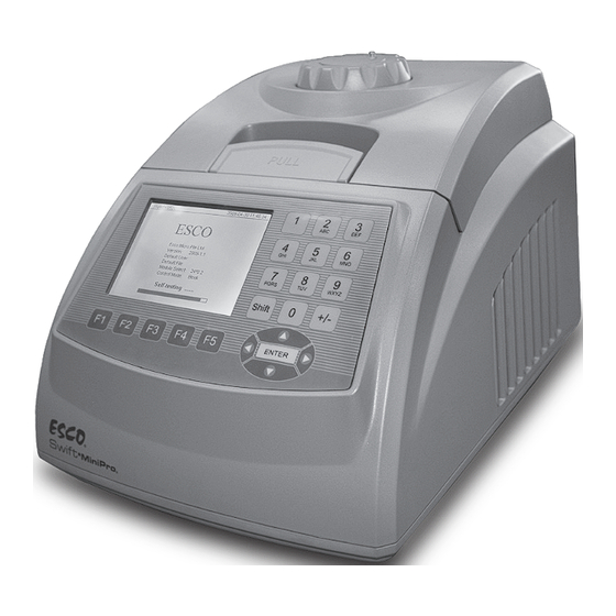
Chapter 1 • Introduction NAME DESCRIPTION NOTE Turn the knob counter-clockwise before closing the lid. Note that the knob can be tightened by Hot lid and Knob The Knob is for adjusting the height of the Hot Lid turning it clockwise, and can be loosened by turning counter-clockwise. -
Page 10: Security Notes
Chapter 1 • Introduction 1.3 Security Notes i. Turn the power OFF and unplug the power cord before performing any procedure. ii. Please read all the instructions thoroughly before maintenance. Always follow this service manual. Keep this service manual well for future reference and review it as necessary. iii. - Page 11 Chapter 1 • Introduction Besides, a multi-channel temperature acquisition device is needed for temperature uniformity and accuracy testing.
- Page 12 Thermal Cyclers • Service Manual...
-
Page 13: Service Procedures
Chapter 2 • Service Procedures CHAPTER 2 SERVICE PROCEDURES 2.1 Fan Replacement 2.1.1 Remove the screws at the bottom of the unit. Refer to Fig.1. Then remove the cover. Fig.1 2.1.2 The location of the fan is as Fig.2 Fig.2 2.1.3 Remove all connectors and take out the fan. -
Page 14: Lcd Replacement
Chapter 2 • Service Procedures 2.14 Replace a new fan. Notes: Please note the air flow direction of the fan and the polarity of the connection wire when replacing the fans. Please mark them to avoid forgetting the correct sequence and make sure the connection is secure. 2.2 LCD replacement 2.2.1 Remove the front cover and see the LCD control board as Fig.5 Fig.5... -
Page 15: Hot Lid Adjust Knob Repair And Replacement
Chapter 2 • Service Procedures 2.3 Hot Lid adjust knob repair and replacement 2.3.1 Use a tweezers to remove the small hot lid lock device. As Fig.7 Fig.7 2.3.2 The cover will be removed together with the lock device. As Fig.8 Fig.8 2.3.3 Remove the small rotate metal ring. As Fig. 9 Fig.9... -
Page 16: Hot Lid Repair And Replacement
Chapter 2 • Service Procedures 2.3.4 Remove the adjustable knob, and see the inner part .As Fig. 10 Fig.10 Note: Most of the time, the hot lid adjustable knob looses because the contact between the four small gears and the big gear is broken. - Page 17 Chapter 2 • Service Procedures 2.4.2 Remove the sticker, as Fig.13 Fig.13 2.4.3 Remove the screw, as Fig. 14 Fig.14 2.4.4 Remove the inner cover and see the hot lid inner part. As Fig.15 Fig.15...
- Page 18 Chapter 2 • Service Procedures 2.4.5 Remove the connector. Measure the resistance, as Fig.16. If the value is out of range, need to repair. Hot lid sensor, Resistance Heating film+ Fuse, Resis- should be around 10K Ω tance should be around 6 Ω Fig.16 2.4.6 Refer to Chapter 2.3, remove the hot lid knob.
-
Page 19: Heating And Cooling Parts Replacement
Chapter 2 • Service Procedures 2.4.9 Remove the 6 screws in above picture, the heat film is as Fig. 19 Fig.19 2.4.10 Remove the solder and replace heat film, fuse or sensor. 2.4.11 Solder the new fuse or sensor, and make sure the fuse contact the hot lid surface well after fixed. 2.5 Heating and Cooling parts Replacement 2.5.1 Pull the handle and put it to the center. - Page 20 Chapter 2 • Service Procedures 2.5.3 Take out the block as Fig. 22. Fig.22 2.5.4 Test the resistance as Fig.23. The resistance of TE should be around 3 Ω, and the resistance of Sensor should be around 10KΩ. If not, need to repair the block. SEN-SINK SEN-SINK SEN-BLOCK...
- Page 21 Chapter 2 • Service Procedures 2.5.6 The heating and cooling part is as Fig. 25 Thermal fuse Block sensor Heat sink sensor Fig.25 2.5.7 Fuse and Heat sink sensor can be replaced but the block sensor can be only replaced by manufacturer. 2.5.8 Replace the only peltier (TE) and install back the heat sink by using Torque screwdriver Φ3 and the torque for four screws are 2.5KG.
-
Page 22: Printed Circuit Board Recognitions And Replacement
Chapter 2 • Service Procedures 2.6 Printed Circuit Board Recognitions and replacement Power supply board CPU control board Fig.26 Replace the Printed circuit boards above. 2.6.1 Wrap the connector by using a damp cotton swab soaked with ethanol until can unplug the plug. 2.6.2 Note the connection sequence of the wires. -
Page 23: Troubleshooting
Chapter 3 • Troubleshooting CHAPTER 3 TROUBLESHOOTING Problem Possible Cause Corrective Action • If no beep sound and the fan is not working, input power or fuse may has problem. • Check if there is power at the wall/building socket. Power Failure •... - Page 24 Chapter 3 • Troubleshooting • If the Switch is broken, Faulty Switch • Replace the whole part as See 1-5 • No beep sound and eliminated the above possibility, the power supplyboard or CPU control board may have connection problem or are defective.
- Page 25 Chapter 3 • Troubleshooting • If voltage is correct, measure the input voltage on the CPU control Board at terminal J13, See drawing 1-7 below to locate terminal J13. • Voltage should be 5VDC. Connection problem/ Defective • If voltage is out of range, check connection between Power supply CPU control board board EJ2 and CPU control board J13, unplug it and plug again or change the cable with plug.
- Page 26 Chapter 3 • Troubleshooting • If the beep sound is normal, fan is working and LCD has no problem, the CPU control board has connection problem or is defective. • Measure the input voltage on the CPU control Board at terminal J13, See drawing 1-9 below to locate terminal J13.
- Page 27 Chapter 3 • Troubleshooting Use Torque screwdriver to tighten the screw, as 1-11. Torque is equal to The screws of the heat sink is 2.5kg. loose 1-11 • Remove the heat sink and thermo film, as Chapter 2.5 • Mesure the resistance of the peltier. If resistance is beyond the area Low heating and as indicated, as 1-12, Peltier failure...
- Page 28 Chapter 3 • Troubleshooting • If the hot lid temperature increase normally, has to find out which part has problem, block or main body. Note: We suggest distributor to keep one set of spare parts to easily change parts and identify where the problem is. •...
- Page 29 If the new main body with old block still have the same problem, the block sensor has problem. Defective block sensor • Contact Esco and return the block for repair. The block sensor must be changed by manufacturer. • Turn over the hot lid, remove the inner cover and see the hot lid inner part.
- Page 30 Chapter 3 • Troubleshooting • Measure the heating film, refer to 1-18. • The resistance should be around 6 Ω. Damaged heating film • If resistance is infinite or zero, replace the heating film as Chapter 2.4. Heating film location as 1-19 Heating film 1-18 1-19...
- Page 31 Chapter 3 • Troubleshooting • Check the plug connection at terminal J16, See drawing 1-22 below to locate terminal J16. Connection problem/Defec- • If no problem, replace the CPU control board. tive control board Note: When replacing power supply board, please re-connect all the wires back correctly.
- Page 32 Chapter 3 • Troubleshooting The connections are sticky, result- • Clean the sticky connections, and re-connect the plug to the ing in a bad connection. socket. Defective CPU control board. • If the problem still exists, chage the CPU control board. As 1-26. Buttons on the touch panel do not work.
- Page 33 Chapter 3 • Troubleshooting • Reconnect the connection wire of the fan, as 1-29 • If still not good, replace the fan. As Chapter 2.1 Damaged fan. Notes: Please note the air flow direction of the fan and the polarity of the connection wire when replacing the fans.
- Page 34 Block sensor damaged or bad connection • If the resistance is infinite or 0, block sensor has problem. Contact Esco and return the block for repair. The block sensor must be changed by manufacturer. During the run, • If the resistance is around 10 KΩ, go to next step.
- Page 35 Measure pin 3&5, 4&6, 5&7, 6&8 separately, normal resistance should be infinite. • If not, the block PCB board has problem. Contact Esco and return the Block PCB board is damaged block for repair. The PCB board must be changed by manufacturer as Peltier location on it is very important.
- Page 36 Chapter 3 • Troubleshooting • Hot lid temperature higher than 115°C. • Turn over the hot lid, remove the inner cover and see the hot lid inner part. As Chapter 2.4. • Note: Don’t remove the hot lid knob first. Hot lid sensor damaged or bad •...
-
Page 37: Appendix
APPENDIX... - Page 38 Thermal Cyclers • Service Manual...
-
Page 39: Appendix 1: Printed Circuit Board Layout
Appendix 1 • Printed Circuit Board Layout APPENDIX 1 PRINTED CIRCUIT BOARD LAyOUT Power supply board ELED1 ELED1 ELED4 ELED4 ELED2 ELED3 ELED2 ELED3 FELED1 FELED1... - Page 40 Appendix 1 • Printed Circuit Board Layout FJ1 : Power supply input. 110VAC +/- 10% or 220VAC +/- 10%. EJ1 : Power supply output for TE: Voltage: 12.8VDC EJ2 : Power supply output for CPU control board. Voltage: 5VDC EJ3 : Power supply output for hot lid and sensor. Voltage: 28VDC EJ4 : Power supply output for fan.
- Page 41 Appendix 1 • Printed Circuit Board Layout Control Board J5 : Display port J10 : Touch panel port J13 : Port connected to power supply board J15 : Block and heat sink sensor port J16 : Hot lid sensor port J17 : Aux-heater control port Note : Display brightness can be adjusted by R39.
- Page 42 Thermal Cyclers • Service Manual...
-
Page 43: Appendix 2: Wiring Diagram
Appendix 2 • Wiring Diagram APPENDIX 2 Wiring Diagram (This diagram is regarded only as a reference, and it is a subject to change without prior notice. We apologize for any inconvenience caused.) - Page 44 Thermal Cyclers • Service Manual...
-
Page 45: Appendix 3: Spare Part List
Appendix 3 • Spare Part List APPENDIX 3 Wiring Diagram PART NUMBER DESCRIPTION PICTURES ESC/ BYQ5041042 Power Supply Part ESC/BYQ5041041 CPU control Board ESC/ BYQ90410300060 Touch Pad A whole part of power filter ESC/ BYQ162300000030 socket, switch and fuse ESC/ BYQ15542000010 LCD Display Part... - Page 46 Appendix 3 • Spare Part List ESC/BYQ904101000050 Heat sink ESC/BYQ504102 Hot lid part ESC/BYQ5041021 Hot Lid Knob ESC/BYQ159110000110 ESC/BYQ904101000040 Peltier Thermal Cyclers • Service Manual...
- Page 48 Esco Healthcare Pte. Ltd. • 21 Changi South Street 1 • Singapore 486 777 Tel. +65 6542 0833 • Fax +65 6542 6920 www.pcrthermalcyclers.com • sales@pcrthermalcyclers.com ©2009 Esco Healthcare Pte. Ltd. Specifications Subject to Change. ES1506_V1_08/09...
Need help?
Do you have a question about the Swift MiniPro SWT-MIP-0.5 Series and is the answer not in the manual?
Questions and answers