Table of Contents
Advertisement
Quick Links
Advertisement
Table of Contents

Related Manuals for Esco Multi-zone ART Workstation


Summary of Contents for Esco Multi-zone ART Workstation
- Page 1 Multi-zone ART Workstation Rev. 3.0 Date of revised 9.22.2020 Rx only...
- Page 2 Esco makes no representations or warranties as to the accuracy of the information contained in this manual. In no event shall Esco be held liable for any damages, direct or consequential, arising out of or related to the use of this manual.”...
- Page 3 Return Procedure Every product returned for refund/credit must be accompanied by a Return Material Au- thorization (RMA) number, obtained from Esco Medical Customer Service. All items being returned must be sent prepaid (freight, duty, brokerage and taxes) to our factory location.
- Page 4 During the warranty period Esco Medical will, at our option, either repair or replace a product that proves to be defective at no charge, provided you return the product (ship- ping, duty, brokerage and taxes prepaid) to Esco Medical.
- Page 5 In an event where the seal must be broken to gain internal access to the instrument, you must first contact Esco Medical Ltd. You will be required to provide us with the serial number for your instrument, as well as a valid reason for breaking the Quality Seal.
-
Page 6: Table Of Contents
Table of contents 1 How to use this manual ......................8 2 Safety warning ........................8 3 Indication for use ........................8 4 About the product ........................9 5 transport, Storage and Disposal .................... 10 5.1 Transport ........................10 5.2 Storage ........................... 10 5.3 Disposal.......................... - Page 7 13.3.5 Service sub-menu ....................33 14 Alarms ..........................34 14.1 Temperature alarms ..................... 34 14.2 Gas pressure alarms ..................... 35 14.3 Multiple alarms ......................36 14.4 Loss of power alarm..................... 36 15 Changing the set points ....................... 36 16 Firmware ..........................36 17 The Laminar Flow.......................
-
Page 8: How To Use This Manual
3 Indication for use The MAW, Multi-zone ART Workstation is a laminar flow workstation that is intended for working with gametes and/or embryos at or near body temperature during in vitro fertili- zation (IVF)/assisted reproduction technology (ART) procedures. The workstation also pro- vides humidified gas to maintain gametes and embryos in the working environment. -
Page 9: About The Product
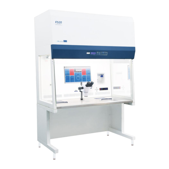
4 About the product The MAW, Multi-zone ART Workstation is a laminar flow workstation that is intended for working with gametes and/or embryos at or near body temperature during in vitro fertili- zation (IVF)/assisted reproduction technology (ART) procedures. The workstation also pro- vides humidified gas to maintain gametes and embryos in the working environment. -
Page 10: Transport, Storage And Disposal
5 transport, Storage and Disposal 5.1 Transport The devices is packed in a carton box, it is wrapped to a polyethylene. The Box is affixed to pallet with the special straps. Visual inspection should be done if there is any damage and then the Multi-Zone ART Work- station is prepared to be transported. -
Page 11: Accessories Supplied
6 Accessories supplied • 1 HEPA filters for input gas supply • 1 USB stick containing Esco Medical Datalogger software and PDF versions of the manuals • 1 gas hood (MAW without compartments) • 1 carry tray (MAW with compartments – 1 carry tray for each compartment) •... -
Page 12: Safety Symbols And Labels
8 Safety symbols and labels There are several user labels on the surfaces of the MAW, Multi-zone ART Workstation ® guide the user. User labels are shown below. Table 7.1 Labels Description Image Packing box label: 1. If stored longer than one year from manufacture date, the unit must be returned to the manufacturer for a new release test. -
Page 13: Important Safety Instructions And Warnings
Description Image USB communication port PC on/off button Compartments numbers are indicated in the top corner of the lid with a label (Only MAW with compartments) Gas inlet on table plate (Only MAW without com- partments) 9 Important safety instructions and warnings 9.1 Before installation 1. -
Page 14: Post Installation
2. Servicing is required according to the service manual, or if the apparatus has been dam- aged in any way, e.g. if the apparatus has been dropped, exposed to rain or moisture, or does not operate normally. The MAW, Multi-zone ART Workstation contains high voltage com- ®... -
Page 15: Mains Connection
11 Mains connection The MAW, Multi-zone ART Workstation comes with a detachable mains power cord. The ® power cord is prepared for the country in which the unit is intended to be used. Do not defeat the safety purpose of the grounding-type plug! A grounding type plug has two blades, and a third prong. - Page 16 Figure 12.3 Gas filter The CO inlet should be connected to a 5 or 6% Premixed CO The gas flow can be controlled digitally with the keys on the table top. The gas will pass through the humidification system. Figure 12.4 Humidification flask Humidification flask tubes are marked with number “1”and “2”.
-
Page 17: Maw Without Compartments
Figure 12.5 Tubes connected to the flask If no humidification is required/ wanted, a U-looped silicone tube must be put from the port marked “Outlet” to the port below. Fill the flask to the bottle mark with sterile water. 12.1 MAW without compartments Figure 12.6 Gas choose from the nozzle The gas will flow through the nozzle in the table top work area. - Page 18 Figure 12.7 Gas nozzle in table top A gas hood must be placed over the outlet. The constant flow will flush the environment so that a correct CO concentration can kept and thus no pH drift will occur. Figure 12.8 Gas hood placed over gas nozzle Keep the lids on the dishes when they are placed under the gas hood.
-
Page 19: Maw With Compartments
12.2 MAW with compartments Figure 12.10 MAW with compartments The gas will flow through and circuit in both compartments by the internal FAN. The FAN will automatically start when the flow is set. Figure 12.11 Gas in compartments Gas system over view Required input gas type: Premixed CO . -
Page 20: Maw With Compartments And Built-In Gas Mixer
Required input gas pressure: gas pressure for on the external source should be 0.6 bar (8.70psi) and must be kept stable. Gas alarm; the alarm level <0.2 bar and >0.8 bar. In case of an alarm remove the sample to safe CO incubator and investigate the cause of the alarm. -
Page 21: User Interface
Gas concentration alarm: audible alarm will start when gas concentration in compartments differs from set point +/-1%. In case if premixed gas intended to be used instead of pure gas refer to trained personal for help! 13 User interface The table 13.1 shows the main keys and their purpose. Table 13.1 Main keys and their purpose Description Image... -
Page 22: Activating The Heat And Gas Flow Controls
13.1 Activating the heat and gas flow controls The heat and gas controls are activated using the on/off switch under the table top. Soon after system activation the main display will show the actual temperature. Change the display reading to gas flow, press key right 13.1.1 Temperature sub-menu The temperature set point can be adjusted in the range from ambient to 40.0 The default temperature set point is 37.0... -
Page 23: Heated Mode
Now the set point can be adjusted up or down with the arrow up or arrow down key. One key press corresponds to a 1 l/h change. If the display does not show the current gas flow reading the arrow right key will toggle between the temperature and gas flow readings. - Page 24 Model 2: Both compartments are on and controlled. Left side and the middle zone are on and controlled Right side of the area is off, as shown, all other zones are heated up to set point. Figure 13.2 Model 2 Mode 3: Both compartments and the left side of the plate are on and controlled.
-
Page 25: Surface Temperatures
Mode 4: Both compartments are on and controlled, rest of the table plate is off as shown. Figure 13.4 Model 4 13.2 Surface temperatures There are 12 separate PID controls for the temperature on the table plate. Each controller is responsible for controlling the temperature of separate zones. Figure 13.5 PID Each of the 12 available zones is equipped with its own separate temperature sensor and heater, allowing the user to adjust the temperature within every zone separately and achiev-... - Page 26 Esco Medical recommends ONLY the YSI 4610 equipped with a 4611 probe. To achieve precision, the measurement device must be both fast in response and accurate.
-
Page 27: Menu Options
Press and hold the SP key. This display will show: Adjust the temperature by pressing the arrow up key 4 times while holding the SP key down. The display will show the steps from 37.1, 37.2, 37.3 and 37.4. let go of the SP key and the value is now stored and calibration value for the T1 area temperature has been modified. -
Page 28: Sub-Menu
Arrow up one stage back and right arrow chose the Service category 13.3.2 Sub-menu All Sub-menus are described in the next passage. 13.3.3 Temperature sub-menu Choose arrow right under temp to enter the temperature sub-menu: Calibrate holding down the SP key and using up and down arrow to adjust: Move to the next sub-menu item with arrow down or one step up with arrow up. - Page 29 Calibrate holding down the SP key and using up and down arrow to adjust: Move to the next sub menu item with arrow down or one step up with arrow up. Calibrate holding down the SP key and using up and down arrow to adjust: Move to the next sub menu item with arrow down or one step up with arrow up.
-
Page 30: Co Sub-Menu (Only For Models With Built-In Gas Mixer)
Calibrate holding down the SP key and using up and down arrow to adjust: Move one step up with arrow up 13.3.4 CO sub-menu (only for models with built-in gas mixer) Press (⇨) on CO2 to enter the CO2 sub-menu First item in the CO sub-menu is CO sensor calibration:... - Page 31 flow rate is shown, it cannot be adjusted. This is the amount of CO gas put into the system while regulating. The volume is shown in liters/hour. Normally it will fluctuate along with the regulation Press (⇩) to move to the next item in the CO sub-menu: internal pressure rate is shown.
-
Page 32: O 2 Sub-Menu (Only For Models With Built-In Gas Mixer)
13.3.5 O sub-menu (only for models with built-in gas mixer) Press (⇨) on O2 to enter the O2 sub-menu First item in the O sub menu is O sensor-1 calibration: Calibrate holding down the SP key and using (⇧) and (⇩) to adjust Move to the next sub-menu item with (⇩) or one step up with (⇧) Toggle O regulation on/off by holding SP key and pressing (⇧) or (⇩) -
Page 33: Service Sub-Menu
internal pressure rate is shown. The value is in bar. It must be >0.2 to ≤0.8 bar (2.90 – 11.60 psi) at all times. It cannot be adjusted on the incubator, and is adjusted on the external gas reg- ulator. Example - How to calibrate the O Using a suitable and calibrated device on one of the gas sample ports, the real O concentration... -
Page 34: Alarms
And the currently installed firmware version: Ver 2.0 is only shown as an example; consult Esco Medical or the local representative for the number of the latest version. Press (⇧) to exit the menu. 14 Alarms On single fault condition, the display will show a red “A” along with the status message of the affected parameter. -
Page 35: Gas Pressure Alarms
14.2 Gas pressure alarms If the CO gas supply is not attached correctly or a wrong CO gas pressure is applied to the system, the MAW, Multi-zone ART Workstation will go into CO pressure alarm mode. “CO2 ® P” will be displayed, indicating wrong incoming gas pressure. The alarm level is < 0.2 and >... -
Page 36: Multiple Alarms
14.3 Multiple alarms When there are concurrent alarms, the display will indicate this by showing first “A MULTI” and then the alarm conditions: The flow will be forced according to the alarms. The temperature alarms have 1 priority. gas level alarms 2 14.4 Loss of power alarm If the power is disconnected, the incubator will give an audio alarm for approximately 4 sec- onds, and the LED in the alarm mute key will flash. -
Page 37: The Laminar Flow
In the menu locate the Service sub menu “Serv”. Choose arrow right under “Serv” to enter the Service sub menu: The service sub menu is locked as default: The display will alternate between: And the currently installed firmware version: Press the arrow up to exit back into the menu 17 The Laminar Flow Figure 17.1 Main keys Fan Button - Turns on and turns off the fan. -
Page 38: Cleaning Instructions
® Periodic cleaning of the device (with no embryos in) Wearing gloves and good handling techniques are important to successful cleaning. Power off the MAW, Multi-zone ART Workstation (underside panel) ® It is recommended that the unit is cleaned with aqueous 70% isopropyl alcohol:... -
Page 39: Manufacturer Recommended Disinfection Procedure
® Inspect the device and if visually clean the device is ready for use. If not visually clean go to step 3 and repeat the procedure Turn on the MAW, Multi-zone ART Workstation (rear panel) ® 19 Heat optimization plates. -
Page 40: Humidification
Figure 21.1 Pin A connector and wire can be supplied by Esco Medical or your distributor. Through the connectors the temperature conditions in the zones can be logged continually User Manual Rev. -
Page 41: All In One Pc
Any logging system that uses standard PT-1000 sensors can be used. Esco Medical can supply an external logging system for the sensors. 22 All in one PC The ART workstation is equipped with a powerful touch enabled AIO PC. Switch on/off the PC by pressing the button below the screen. - Page 42 Figure 22.2 The main view Dotted lines will appear instead of values when the signal is lost. Once the signal is established, numeric values will be shown. Figure 22.3 The zone operation mode The blue color signifies that the zone is in normal operation mode. If there is an alarm, the color will shift to red on the relevant zone.
- Page 43 Some models of workstation contain compartments. In this case, the zone will have black border and two temperature values (bottom and lid). Figure 22.4 At the top of the screen 4 navigation buttons are placed in the middle and 3 actions buttons in the right-hand corner.
- Page 44 two separate temperature curves will be shown. Figure 22.5 Figure 22.6 The graph view A zoom function is available by touching the screen and swiping the finger left over the area that should be zoomed. Pressing the reset button will jump back to full view. If there are data accumulated, it is possible to shift between a “week”, “day”...
- Page 45 Figure 22.7 The historical data Pressing the red “Alarm” button in the top will bring up the graphical alarm view. Alarm conditions for the parameters are shown as red on the time line, thus making easy identifi- cation possible. Figure 22.8 The graphical alarm view Pressing the red “report”...
- Page 46 Figure 22.9 The report mode The 3 action buttons are located at the right-hand side. The button “reconnect” allows the system to reconnect with the sensors (in case of data loss due to USB connection issues). The button “minimizes” - toggles the full screen format off for the workstation logger. The button “exit”...
-
Page 47: Maintenance
• Remove all the samples and place them in an alternative or backup device that is not affected by the problem. • The MAW, Multi-zone ART Workstation® will lose its temperature below a safe level in around 5 minutes. In case of a single temperature alarm on the unit: User Manual Rev. -
Page 48: User Troubleshooting
• Remove all the samples and place them in an alternative or backup device that is not affected by the problem. • The MAW, Multi-zone ART Workstation will lose its temperature below a safe level ® in around 5 minutes In case of a single temperature alarm on the unit: •... - Page 49 Please refer to software installa- not properly installed tion guide Table 25.4 Display Symptom Cause Action Contact your Esco Medical Dis- Missing segment(s) in display Failure in the PCB tributor to replace the PCB Table 25.5 Keyboard Symptom Cause Action...
-
Page 50: Specifications
26 Specifications Table 26.1 MAW, Multi-zone ART Workstation specifications ® Technical specifications MAW-4D MAW-6D MAW-6D DUAL MAW-6D MP Work area dimensions 1870 x 500 x 710 mm 1260 x 500 x 710 mm (WxDxH) External dimensions without 1340 x 640 x 1300... -
Page 51: Electromagnetic Compatibility
Guidance and manufacturer’s declaration – electromagnetic immunity The MAW, Multi-zone ART Workstation is intended for use in the electromagnetic environment specified be- ® low. The customer or the user of the MAW, Multi-zone ART Workstation should assure that it is used in such ® an environment. - Page 52 Guidance and manufacturer’s declaration – electromagnetic immunity The MAW, Multi-zone ART Workstation is intended for use in the electromagnetic environment specified ® below. The customer or the user of the MAW, Multi-zone ART Workstation should assure that it is used in ® such an environment.
- Page 53 ® radiated RF disturbances are controlled. The customer or the user of the MAW, Multi-zone ART Workstation can help prevent electromagnetic interference by maintaining a minimum distance between portable and ®...
Need help?
Do you have a question about the Multi-zone ART Workstation and is the answer not in the manual?
Questions and answers