Table of Contents
Advertisement
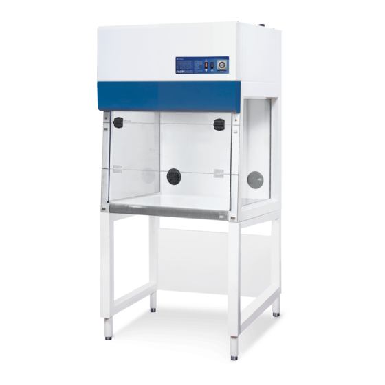
Thank you for purchasing this Esco Polymerase Chain Reaction
Cabinet. Please read this manual thoroughly to familiarize yourself
with the many unique features and exciting innovations we have built
into your new equipment. Esco provides many other resources at our
website, www.escoglobal.com, to complement this manual and help
you enjoy many years of productive and safe use of your Esco
products.
North America
Esco Technologies, Inc.
903 Sheehy Drive, Suite F, Horsham, PA 19044, USA
Tel 215-441-9661 • Fax 484-698-7757
escolifesciences.us • eti.admin@escoglobal.com
Rest of World
Esco Micro Pte. Ltd.
21 Changi South Street 1 • Singapore 486 777
Tel +65 6542 0833 • Fax +65 6542 6920
www.escoglobal.com • mail@escoglobal.com
Esco Polymerase Chain Reaction Cabinets
(SCR-2A, PCR-3A, PCR-4A)
Service Manual Version E - Released January 2021
Service Manual
Polymerase Chain Reaction
Cabinets
Advertisement
Table of Contents

Related Manuals for Esco Streamline SCR-2A


Summary of Contents for Esco Streamline SCR-2A
- Page 1 Esco provides many other resources at our website, www.escoglobal.com, to complement this manual and help you enjoy many years of productive and safe use of your Esco products. North America Esco Technologies, Inc.
- Page 2 Esco makes no representations or warranties as to the accuracy of the information contained in this manual. In no event shall Esco be held liable for any damages, direct or consequential, arising out of or related to the use of...
-
Page 3: Table Of Contents
Table of Contents INTRODUCTORY PAGES Table of Contents Manual Revision History Warranty Terms and Conditions Introduction 1. Products Covered 2. Safety Warning 3. Document Management 4. Limitation of Liability 5. European Union Directives on WEEE and RoHS 6. Symbols Declaration of Conformity SERVICE SECTION Chapter 1 –... -
Page 4: Manual Revision History
MANUAL REVISION HISTORY DATE SERIAL # OF 1 UNIT REV. NO. DESCRIPTION OF CHANGE REFERENCE RELEASED FOR IMPLEMENTATION 13-Aug-2019 Updated certification testing; Added manual revision history 20-Sep-2019 Updated Total airflow for HEPA filter leak test 09-Jun-2020 Removed airflow and sash alarm 22-Jan-2021 Updated Declaration of Conformity... -
Page 5: Warranty Terms And Conditions
Esco that these parts were defective at the time of being sold, and that all defective parts shall be returned, properly identified with a Return Authorization. - Page 7 For international distributors, warranty period starts two months from the date the equipment is shipped from Esco facility. This allows shipping time so the warranty will go into effect at approximately the same time the equipment is delivered to the user. The warranty protection extends to any subsequent owner during the warranty period.
-
Page 8: Introduction
If you require replacements for any of the provided documentation (including factory test reports) you can request copies from Esco Customer Services*. Please provide the following information when making requests for replacement documents: ... -
Page 9: Limitation Of Liability
The disposal and/or emission of substances used in connection with this equipment may be governed by various local regulations. Familiarization and compliance with any such regulations are the sole responsibility of the users. Esco’s liability is limited with respect to user compliance with such regulations. 5. European Union Directive on WEEE and RoHS The European Union has issued two directives: •... -
Page 10: Declaration Of Conformity
Low Voltage : EN 61010-1:2010 : EN 61326-1:2013 Class B More information may be obtained from Esco’s authorized distributors located within the European Union. A list of these parties and their contact information is available on request from Esco ____________________... - Page 11 Low Voltage : EN 61010-1:2010 : EN 61326-1:2013 Class B More information may be obtained from Esco’s authorized distributors located within the European Union. A list of these parties and their contact information is available on request from Esco ____________________...
-
Page 12: Chapter 1 - Re-Certification By Service Personnel
Esco products. For more information on the nearest training course, please contact Esco. Service providers should familiarize themselves with the basic operating principles of products before working on them. -
Page 14: Certification Flowchart
1.1 Certification Flowchart Polymerase Chain Reaction Cabinets... -
Page 15: Airflow Adjustment
1.2 Airflow Adjustment The speed controller is located in the electrical panel at the top of the cabinet. Plug the multimeter probes to the Motor Voltage Sampling Port. Use the multimeter to take the motor voltage with corresponding air velocityreading. Adjust the airflow by adjusting the speed controller. -
Page 16: Unit Re-Certification
1.3 Unit Re-Certification 1.3.1 SCR-A 1.3.1.1 Airflow Velocity and Uniformity Test Set up a calibrated airflow meter within the interior of the cabinet to measure filter airflow at a distance of 15 cm from the filter face. Set the measurement point at the center of the filter face area. Approx 2 ft ... - Page 17 1.3.1.2 HEPA/ULPA Filter Leak Test The filter was challenged with PAO aerosol of fixed concentration. The aerosol was evenly distributed throughout the supply (positive) cabinet plenum. An aerosol photometer was used to monitor aerosol penetration downstream of the filter, and to scan for the presence of leaks. Use calculated method, along with ATI TDA-4Blite aerosol generator, the upstream aerosol concentration can be calculated using the following equation: 13,500��...
- Page 18 4 feet Cabinet Model 3 feet 1219 (48) Width = w (mm) (in) 914 (36) 457 (18) Depth = h (mm) (in) 457 (18) 300 (12) Distance from walls = a (mm) (in) 300 (12) Left to Right 619 (24.4) Distance apart = x (mm) (in) 314 (12.4) 150 (6)
- Page 19 4 feet Cabinet Model 3 feet 1235 (48.6) Width = w (mm) (in) 930 (36.6) 530 (20.9) Depth = h (mm) (in) 530 (20.9) 300 (11.8) Distance from walls = a (mm) (in) 300 (11.8) Left to Right 635 (25) Distance apart = x (mm) (in) 330 (12.9) Front to...
- Page 20 1.3.1.5 Noise Level Test The cabinet was isolated in a noise-controlled environment and a noise level meter was set up at a distance of 30 cm in front of the cabinet and 38 cm above the work surface. With the cabinet running under normal parameters, the instrument was used to obtain a noise level of the cabinet during normal operation.
-
Page 21: Pcr-A
PCR-A 1.3.2 1.3.2.1 Airflow Velocity Test Put the anemometer on a plane that is 150 mm (6 in.) from the filter face, and measure the airflow using the grid below: 4 feet Cabinet Model 3 feet 1219 (47.9) Width = w (mm) (in) 914 (36.6) 457 (17.9) Depth = h (mm) (in) - Page 22 1.3.2.2 Particle Count Test Use a particle counter with sampling rate of 0.028 m (1 ft. ) of air per minute. Put the particle counter sampling cone inside the work zone, following the grid below: 4 feet Cabinet Model 3 feet 1219 (48) Width = w (mm) (in) 914 (36)
- Page 23 1.3.2.3 HEPA/ULPA Filter PAO Leak Test The airflow filter was challenged with PAO aerosol of fixed concentration. The aerosol was evenly distributed throughout the cabinet plenum. An aerosol photometer was used to monitor aerosol penetration downstream of filter, and to scan for the presence of leaks. Use calculated method, along with ATI TDA-4Blite aerosol generator, the upstream aerosol concentration can be calculated using the following equation: 13,500...
- Page 24 1.3.2.4 Light Intensity Test A light intensity meter was used to measure light intensity at work surface level of the cabinet: 4 feet Cabinet Model 3 feet 1235 (48.6) Width = w (mm) (in) 930 (36.6) 530 (20.9) Depth = h (mm) (in) 530 (20.9) 300 (11.8) Distance from walls = a (mm) (in)
- Page 25 1.3.2.5 Noise Level Test The cabinet was isolated in a noise-controlled environment and a noise level meter was set up at a distance of 30 cm in front of the cabinet and 38 cm above the work surface. With the cabinet running under normal parameters, the instrument was used to obtain a noise level of the cabinet during normal operation.
- Page 26 1.3.2.6 UV Radiation Intensity Test UV radiation intensity meter was used to obtain light intensity at work surface level within the cabinet. Readings were taken along the front to back centerline within the interior work area: All units are μW/cm Cabinet Model PCR 3 feet 4 feet...
-
Page 27: Replacement Of Filter
1.4 Replacement of Filter 1.4.1 SCR-A Unscrew and remove front cover Unscrew and remove the perforated shelf Unscrew and remove the UV lamp and unsnap the holder Unbolt and remove the filter clamp. Makesure to hold the filter when doing this. Carefully remove the filter and replace Reverse above steps Re-certify the cabinet... -
Page 28: Pcr-A
1.4.2 PCR-A Unscrew and remove front cover Unscrew and remove the perforated shelf Unscrew and remove the UV lamp and unsnap The holder Unbolt and remove the filter clamp. Ensure to hold the filter when doing this Carefully remove the filter and replace Reverse above steps Re-certify the cabinet Polymerase Chain Reaction Cabinets... -
Page 29: Replacement Of Blower
1.5 Replacement of Blower 1.5.1 SCR-A Remove the black foam at top exhaust. Unscrew the top metal mesh and remove. Remove the blower wiring connection. Unscrew the blower mounting house and take out. Replace the blower and reverse above steps. -
Page 30: Pcr-A
1.5.2 PCR-A Remove the black foam at top exhaust Unscrew the top metal mesh and remove Disconnect the blower wiring Unscrew the blower mounting house and take out Replace the blower and reverse above steps Re-certify the cabinet Polymerase Chain Reaction Cabinets... -
Page 31: Fluorescent Lamp And Uv Lamp Replacement
1.6 Fluorescent Lamp and UV Lamp replacement 1.6.1 Replacing the fluorescent lamp 1. Before changing the fluorescent bulbs, ensure that the cabinet is powered down and disconnected from the electrical supply 2. Locate the bulbs. 3. Remove the power clips at the ends of the bulbs by gently pulling whilst holding the bulb steady. 4. -
Page 32: Chapter 2 - Troubleshooting
Chapter 2 – Troubleshooting This section helps you troubleshoot some of the common problems you might face while operating this clean bench. Should you have any queries left unanswered here, please feel free to contact Esco. Problem 1 — Cabinet does not start... - Page 33 If there is power on wall socket and cord, check whether • circuit breaker has tripped. • The circuit breaker can be found right beside the cabinet power inlet. Circuit breaker has tripped Note: If circuit breaker has tripped, do not reset the (for PCR only) breaker before checking all electrical components and wiring connections.
- Page 35 • Unit must be turned on to perform this test. • See Layout A at the end of this section to locate the SMPS. It is inside the electrical panel and covered by a stainless steel box. • Checking SMPS output: Disconnect the 5-pin connector attached to the SMPS output then measure the DC voltage between Red (pin 1) and White (pin 2) cables on Defective power supply...
- Page 36 Restart the cabinet 2 to 4 times. • • The Main Board is defective if the Main Board incoming supply is between 6.75 – 8.25 VDC AND: All LED’s on the control panel are off The LCD is blank Defective main board There is no Buzzer sound (for PCR only) •...
- Page 37 • Ensure the following are correct: Main Board is operational. Flat Ribbon cable is installed correctly to relay board and main board and shows no physical damage. Relay board has the correct incoming voltage (6.75 – 8.25 VDC). Check all fuses on relay board: Turn off power by Defective relay board unplugging the cabinet from the main supply.
-
Page 38: Problem 2 - Blower Doesn't Function
Problem 2 — Blower does not function PROBLEM POSSIBLE CAUSE CORRECTIVE ACTION For PCR: • Switch on the Fan by pressing Fan button on control panel (see Fig. 2.1). Enter the Fan PIN number if required (default is 0001) • •... - Page 39 Fig 2.3 • Unplug the cabinet from main supply. • Open electrical panel and see Layout A/B at the end of this section to locate the motor speed controller. • Add a jumper wire between the 2 cables going to speed control (see Fig.
- Page 40 Unplug the cabinet from main supply. • • See Layout A/B at the end of this section to locate the capacitor near the blower compartment. Refer to Fig. 2.6 below, disconnect two cables of • capacitor. Using a capacitance meter or a multimeter set to •...
- Page 41 For PCR only: • Unplug the cabinet from the main supply. Check LS1 relay on the Relay Board (see Figure 2.7) • • Make sure all wiring and connections are correct. On terminal J2, check the Normally Open (NO) to •...
- Page 42 Check the Fan for overheating – The motor has an in- • built thermal cut off. Wait 60 minutes with the FAN turned off and then try to • Auto-thermal cut-off restart. • If the FAN restarts determine why there is excessive heat in the cabinet.
-
Page 43: Problem 3 - Airflow Is Not At Nominal Velocity
Problem 3 — Airflow is not at nominal velocity PROBLEM POSSIBLE CAUSE CORRECTIVE ACTION • Ensure that there are no external sources of airflow disturbance like air conditioner vent, window or incidences of door opening or people walking fast near the cabinet. - Page 44 Switch “ON” the blower fan. • • Open the top access cover and locate electrical panel inside. • Refer to Fig. 3.1 (PCR) or Fig. 3.2 (SCR) below to locate the motor voltage sampling port. Using voltmeter, measure AC voltage at the motor •...
-
Page 45: Problem 4 - Contaminated Samples
• Switch “ON” the blower fan. • Lift-up the top pre-filter and open cover to access the electrical panel. Locate Motor Voltage Sampling Port. • Plug in the voltmeter to the Motor Voltage Sampling Port. • Measure the actual airflow velocity using anemometer or flow hood. -
Page 46: Problem 5 - Excessive Fan Noise
Problem 5 — Excessive fan noise PROBLEM POSSIBLE CAUSE CORRECTIVE ACTION • Refer to Problem 2: Blower doesn’t function – possible Faulty Capacitor cause 4 – Faulty capacitor. • Plug the cabinet power cord to the wall outlet and lift-up the top pre- filter. -
Page 47: Problem 6 - Blank Lcd
Problem 6 — Blank LCD PROBLEM POSSIBLE CAUSE CORRECTIVE ACTION • Unplug the cabinet from the main supply. • Open the top access cover and locate electrical panel behind it. • Open electrical panel and see Layout A at the end of this Connection problem section to locate the main board inside electrical panel. -
Page 48: Problem 7 - Inoperative Buttons
Problem 7 — Inoperative buttons PROBLEM POSSIBLE CAUSE CORRECTIVE ACTION • Unplug the cabinet from the main supply. • Open the top access cover and locate electrical panelinside. See Layout A at the end of this section to locate the main •... - Page 49 Inoperative buttons Fig 7.4 • Replace them one by one, to check which one(s) among Defective Cable and / or them is/are defective. Interface Board and / or • Replace the defective part(s). keypad Polymerase Chain Reaction Cabinets...
-
Page 50: Problem 8 - Lights Always Off
Problem 8 — Lights always OFF PROBLEM POSSIBLE CAUSE CORRECTIVE ACTION Replace the faulty fluorescent tube. • Faulty fluorescent tube • Fluorescent tube is located inside the blue panel (Refer to Fig. 7.3 for lamp location and replacement). For PCR: •... - Page 51 For PCR: • Unplug the cabinet from the main supply. See Layout A at the end of this section to locate the relay • board, fluorescent ballast, and connector B inside electrical panel. • Check forany loosedor bad connectionbetween relay board, fluorescent lamp ballast, and female connector B.
-
Page 52: Problem 9 - Cannot Turn On Uv Lamp
Problem 9 — Cannot turn on UV lamp PROBLEM POSSIBLE CAUSE CORRECTIVE ACTION WARNING: Before turning the UV lamp on, make sure that the hinged window is closed. Also ensure that you are protected. For PCR: • Close the hinged window for UV mode position (fully closed, see Fig. - Page 53 For PCR: • Move hinged window to Fully Closed position. The LCD should show “UV MODE”. Please ensure that the hinged window is fully closed. • Check the magnetic switch located behind the front right corner of the table (right side). Refer to Fig. 9.3 below for the location.
- Page 54 For PCR: • Open the top access cover and locate electrical panelinside. See Layout A at the end of this section to locate the UV • ballast, relay board, and connector B inside electrical panel. • Turn on the cabinet by connecting to the main supply, then switch on the UV by pressing UV button on membrane/keypad.
- Page 55 For PCR: • Unplug the cabinet from the main supply. Open the top access cover and locate electrical panel • behindit. See Layout A at the end of this section to locate the relay • board, UV ballast, and connector B at electricalpanel. •...
- Page 56 For PCR: • Unplug the cabinet from the main supply. Open the top access cover and locate electrical panel inside. • • See Layout A at the end of this section to locate the relay board inside electrical panel. • Check LS8 relay and fuse F8 on the relay board (see Fig.
- Page 57 LAYOUT A Polymerase Chain Reaction Cabinets...
- Page 58 LAYOUT B...
-
Page 59: Chapter 3 - Product Specifications
0.95 m (34 ft 1.19 m (42 ft Maximum*** * Noise reading in open field condition / anechoic chamber ** Additional voltages may be available; contact Esco for ordering information. *** Cabinet only; excludes optional stand. Polymerase Chain Reaction Cabinets... -
Page 61: Appendix
APPENDIX... -
Page 62: Appendix A: Log Record
APPENDIX A: LOG RECORD Cabinet : Serial Number: Person in Charge: This log record should be used by the operator to record any new agent/virus/bacteria/germs that has been introduced to the cabinet during its operation, problems encountered, etc. Any decontamination procedure performed by either the user or the technician should be recorded down as well. -
Page 63: Appendix B: Further Information And Reference Materials
IEST-G-CC1004: Sequential Sampling Plan for Use in Classification of the Particulate Cleanliness of Air in Cleanrooms and • Clean Zones.1999. Institute of Environmental Sciences and Technology, Illinois, USA. WEBSITES Esco Micro Pte. Ltd. www.escoglobal.com International Organization for Standardization (ISO) www.iso.org Institute of Environmental Sciences and Technology (IEST) www.iest.org...
Need help?
Do you have a question about the Streamline SCR-2A and is the answer not in the manual?
Questions and answers