
Subscribe to Our Youtube Channel
Related Manuals for Maico Compaktbox ECR 12 EC


Summary of Contents for Maico Compaktbox ECR 12 EC
- Page 1 Assem b l y a n d Op erati n g M an u a l Compaktbox Compact Supply air unit 137771 ECR 12 EC ECR 16 EC ECR 20 EC ECR 25 EC English ECR 31 EC...
- Page 2 The product supplied may therefore differ from the illustration. The original manual has been produced in the German language. Information updated: print 11.04.2018 We reserve the right to make changes MAICO Elektroapparate Fabrik GmbH Steinbeisstraße 20 D-78056 Villingen-Schwenningen Tel. +49 7720 / 694-0 Fax. +49 7720 / 694-263 info@maico.de...
-
Page 3: Table Of Contents
12.1. Disassembling the product.............22 12.2. Disposal ..................22 13. Troubleshooting..................23 13.1. Low-current fuses ................23 13.2. Fault diagnosis chart ..............24 13.3. Possible operating faults..............24 14. Technical data ..................25 15. Appendix ....................26 15.1. List of parameters ................26 15.2. Wiring diagrams ................27 www.maico-ventilatoren.com... -
Page 4: Important Information
The ruck fan is a component in terms of the machine directive 2006/42/EC (partly completed ma- The MAICO fan is a component in terms of the machine directive 2006/42/EC (partly completed ma- chinery). The product is a not ready-for-use machine in terms of the machine directive. It is intended chinery). -
Page 5: Improper Use
Overhead load warning! Indicates possible hazards due to overhead loads. Failure to observe the warnings may result in death, injury and/or damage to property. Important instructions follow! Instructions for safe, optimum use of the product. www.maico-ventilatoren.com... -
Page 6: Adhere To The Following Instructions
• 2.5.6. During maintenance and repair If operated correctly, ruck products only require a minimum amount of maintenance. Please If operated correctly, MAICO products only require a minimum amount of maintenance. Please • • follow all of the instructions given in section 10 in this respect. -
Page 7: Delivery Contents
1 x ECR compact supply air unit • • 1 x remote control with control cable 1 x remote control with control cable • • 1 x installation and operating manual 1 x installation and operating manual • • www.maico-ventilatoren.com... -
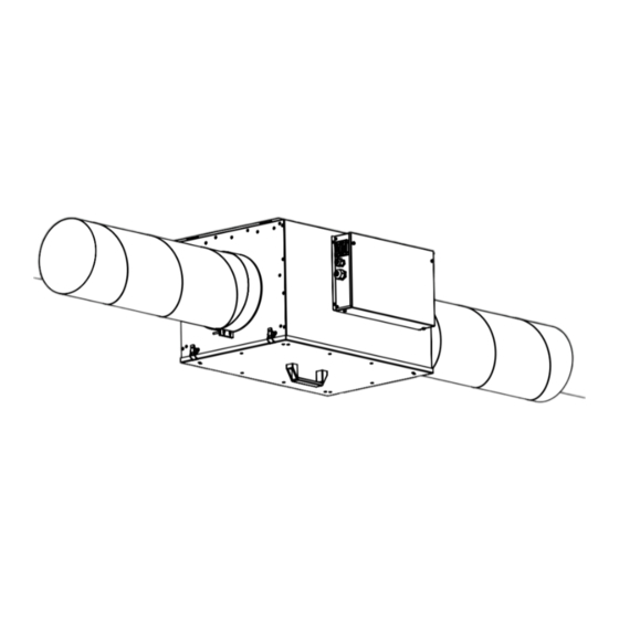
Page 8: Product And Performance Description
English Product and Performance description The FFH compact supply air unit is a complete, ready-to-use supply air unit with Z-Line air filter, fan, The ECR compact supply air unit is a complete, ready-to-use supply air unit with Z-Line air filter, fan, electric heater and integrated control. -
Page 9: Transport And Storage
2/3 the unit‘s maximum pressure so that an adequate air output can still be achieved. This will prevent malfunction. Pressure losses in the duct system are adversely affected by: the length of the duct system, small • pipe or duct cross-section, elbows, additional filters, valves, etc. www.maico-ventilatoren.com... -
Page 10: Electrical Connection
English 6.1. Permitted installation positions Abb. 6b: Ceiling installation 137771 Abb. 6a: Abb. 6c: Wall installation, connec- Wall installation, air tions upwards. flowing upwards. Electrical connection Electricity warning (hazardous voltage) • 137771 Failure to observe the hazard may result in death, injury or damage to property. »... -
Page 11: Overcurrent Protection
The extra-low voltage control cables must be laid separately from the mains cables. 7.1. Overcurrent protection The unit may only be operated with the correct overcurrent protection. • This must be established by a qualified electrician. • The recommended protection is shown in the enclosed wiring diagram. • www.maico-ventilatoren.com... -
Page 12: Wiring Diagrams
English 7.2. Wiring diagrams FFH 125 EC / FFH 150 EC / FFH 160 EC Units / Model: FFH 125; FFH 150; FFH 160 Units / Model: ECR 12 EC; ECR 16 EC 10 11 12 1 2 3 L1L2 L3 N PE 1 2 3 4 5 6 7 8 9 1 2 3 4 5 6 7 8 9 3 N PE... -
Page 13: Commissioning
Warning: When the voltage is connected the blower starts up at the middle stage for about 6 sec. After four minutes the blower switches back off again automatically. In the shut-off delay the unit continues to run until the supply air temperature is at <40 ° C. Then the unit turns off. www.maico-ventilatoren.com... -
Page 14: Operation
English Operation 9.1. Control unit The control unit enables the control and input of the unit‘s various functions. The control unit has an integrated temperature sensor (set-point sensor) for measuring the room temperature. The display shows the various operating parameters and error messages. You can select individual menu points or change values with the various buttons. -
Page 15: Adjustment Of The Control Unit Parameter
Then press the „Mode button“ (M) for at least 2 seconds. The parameters will be saved and the menu will close. The display switches into operating mode. DEUTSCH ENGLISH FRANCAIS DANSK ESPAÑOL NEDERLANDS PORTUGUÊS POLSKI SLOVENCINA ROMANA Русский TURKISH SLOVENSCINA HRVATSKI MAGYAR MONGOLOOR 2 sec SUOMI www.maico-ventilatoren.com... -
Page 16: Menu Management
English 9.2. Menu management Control unit parameter 5 sec V 3.0 Status ON / OFF Language setting 21,0° 22,0° Status display Set-point temperature Zeit- 21,0° 5:30 ON Fan stage schaltuhr 18:30 OFF 5 sec ... -
Page 17: Menu Functions
The values set are saved even when there is a power failure or if the battery in the control unit • 6:30 ON runs down. Only the current time and day of the week have to be reset. 19:30 OFF Note: Instructions on changing the clock battery are give in section 10.3.2. www.maico-ventilatoren.com... -
Page 18: Operating Variables Menu
English Setting the current time / day From the status display, press button A (▲) and B (▲) for approximately 5 s to get to the menu for setting the current time and the current day of the week . 21,0°... -
Page 19: Parameter Settings Menu
P6 HEATER POWER are given in Section 14 „Technical Data“. 3 KW The setting depends upon the type of device. The values for the setting P6 HEATER POWER are given in Section 14 „Technical Data“. 4,5 - 9 KW www.maico-ventilatoren.com... -
Page 20: Additional Functions
English P 7 Temperature correction The control sensor can be calibrated with parameter P 7. Buttons B (▲ and ▼) can be used to correct P7 TEMP.ADJUSTME the control sensor within a range from -5 °C to 5°. 0,0° Control sensor for room temperature control = sensor in the control unit. •... -
Page 21: Cleaning And Care
If operated correctly, ruck products only require a small amount of maintenance. If operated correctly, MAICO products only require a small amount of maintenance. The following work should be performed at regular intervals, in accordance with health and safety... -
Page 22: Changing The Battery
The unit must not be reconfigured. ruck Ventilatoren‘s warranty only applies for the configuration delivered. MAICO Ventilatoren‘s warranty only applies for the configuration delivered. The warranty will cease to apply after any reconfiguration or expansion. The warranty will cease to apply after any reconfiguration or expansion. -
Page 23: Troubleshooting
If you have not been able to remove the fault, please contact the manufacturer. The contact address can be found at www.ruck.eu or on the back cover of this operating and installation manual. can be found at www.maico-ventilatoren.com or on the back cover of this operating and installation manual. -
Page 24: Fault Diagnosis Chart
English 13.2. Fault diagnosis chart If a fault occurs on the unit one or more fault messages will appear on the display. Move between the various faults with buttons A (▲ and ▼). A fault is acknowledged with button B (▲). It is not possible to use the control unit until all of the faults have been removed and acknowledged. -
Page 25: Technical Data
82+82+30 82+82+30 Ø D Assembly size Ø B Ø D Fig. 17: Outside dimensions of the control unit. 125987 Ø B Ø D Fig. 18: Installation dimensions of the control unit. Fig. 19: Dimensions of the supply air unit. www.maico-ventilatoren.com... -
Page 26: Appendix
English 15. Appendix 15.1. List of parameters The following table lists all of the parameters that are displayed on the control unit, some of which may be changed. Section 9.3.3 „Parameter settings menu“ gives full instructions on operating and setting the corresponding parameters. Denotation Range of values Factory setting... -
Page 27: Wiring Diagrams
ECR 12 / ECR 16 138551 2.50 mm² Black 2.50 mm² Green-Yellow Freigabe Gerät unit enable Optional +24V +24V Störung Gerät unit fault Klappenantrieb flap drive open close slow middle Abluftventilator fast exhaust air fan 1.50 mm² Blue 1.50 mm² Black www.maico-ventilatoren.com... - Page 28 English ECR 20 / ECR 25 / ECR 31 138551 2.50 mm² Black 2.50 mm² Black 2.50 mm² Black 2.50 mm² Green-Yellow Freigabe Gerät unit enable Optional +24V +24V Störung Gerät unit fault Klappenantrieb flap drive open close slow middle Abluftventilator fast exhaust air fan...
- Page 29 English Connection electrical heating ECR 12 / ECR 16 138551 2.50 mm² Blue +24V 1.50 mm² Black 1.50 mm² Black www.maico-ventilatoren.com...
- Page 30 English Connection electrical heating ECR 20 138551 2.50 mm² Blue +24V 1.50 mm² Black 1.50 mm² Black Tel. +49 7720 / 694 - 0 Fax. +49 7720 / 694 - 263...
- Page 31 English Connection electrical heating ECR 25 / ECR 31 138551 2.50 mm² Blue +24V 1.50 mm² Black 1.50 mm² Black www.maico-ventilatoren.com...
- Page 32 English Connection pressure switch 138551 1 2 3 Druck auf 20PA einstellen Druck-Schalter Schlauch Düse (Blau) auf P2 pressure switch Schlauch Motorplatte (Rot) auf P1 Datum 21.03.2017 ruck Ventilatoren GmbH Anschluss Druck-Schalter =FFH 138551_00 Max-Planck-Strasse 5 Bearb. S. Kuhbach D-97944 Boxberg connection pressure switch Gepr.
- Page 33 English Notes www.maico-ventilatoren.com...
- Page 34 Ventilatoren the exclusive property of MAICO Elektroappa- GmbH. rate Fabrik GmbH. It may not be reproduced or given to third par- It may not be reproduced or given to third par- ties without its consent.
Need help?
Do you have a question about the Compaktbox ECR 12 EC and is the answer not in the manual?
Questions and answers