
Related Manuals for EliteModels Easy Stik 10cc ARF


Summary of Contents for EliteModels Easy Stik 10cc ARF
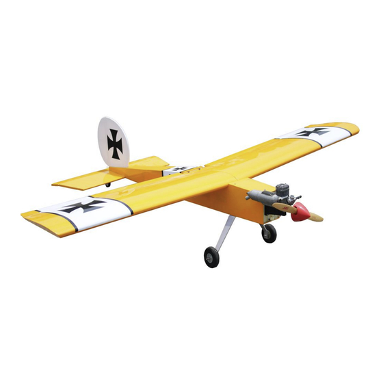
- Page 1 Easy Stik 10cc ARF Specifications Wingspan: 61.4 in (1560 mm) Length: 49.2 in (1250 mm) Flying Weight: 4.5– 5.6 lb (2050 – 2600 g)
- Page 2 Dear Customer, Congratulations on your purchase of the Easy Stik 10cc ARF from Value Hobby. We thank you for your generous support, and hope you enjoy your new airplane. At Value Hobby, we hope to offer competitive prices, good performance, and products that you can setup and use with ease.
- Page 3 Before Starting Assembly Unpack your airplane and examine the components. Check for damage of any kind. If you see any damage, please contact Value Hobby immediately. Airframe Parts 1. Fuselage 2. Wing panel 3. Horizontal stabilizer and elevator 4. Vertical fin and rudder...
- Page 4 1. Gas tank x 1 2. Motor mount x 1 3. Bolts for motor mount x 4 4. Washer for motor mount x 4 5. Locknut for motor mount x 4 6. Engine trail x 1 set 7. Bolt for engine trail x 4 8.
- Page 5 RECOMMENDED SETUP(not included) Product Quantity GForce G32 Brushless Motor(4250-800KV) XYH-MT-0177 Hobbywing Skywalker 80A ESC HWG-SC-4446 Power HD 1501MG Servo PHD-SV-0370 GForce 3300mAh 4S LiPO RFI-LP-1782 12 x 6 Prop GFH-MP-2661 OTHER ACCESSORIES (NOT INCLUDED) Product Quantity 5-Pack 18in Servo Extension VHB-AC-5610 5-Pack 6in Servo Y-Harness VHB-AC-5570...
-
Page 6: Wing Assembly
Wing Assembly Join the aileron to the wing panel through hinges, and apply some thin CA to hinges. Flex the aileron up and down several times to break in the hinges. Locate the following parts: Wing joiner x 1 Wing dowel x 2 Aileron pushrod x 2 Control horn set x 2 Clevis x 2... - Page 7 There are two openings for servo and servo wire on Connect the pushrod to the easy connector, then the wing panel, first use the knife to remove the position the control horn on the aileron to make covering from the openings, then install the servo sure the pushrod wire is 90 degree with the hinge with servo arm to the servo opening and the servo line and the hole in the control horn aligned with...
- Page 8 Apply epoxy to the wing joiner, and joint areas of Position the joined wing on a flat surface, waiting the wing panels. for the epoxy to cure. Install the wing to the fuselage by aligning the dowels to the holes. Put two wing panels together through the wing joiner.
-
Page 9: Tail Assembly
Check the alignment of the stabilizer to the wing. Tail Assembly Position the stabilizer so the measurements from the stabilizer tips to the wing tips are equal. Also Locate the following parts: check that the stabilizer is parallel to the wing. Lightly sand the stabilizer saddle if adjustments are Pushrod for elevator and rudder x 2 required. - Page 10 Use a felt-tipped pen to trace the outline of the Use a knife to remove the covering from the fuselage on the stabilizer. Use a hobby knife and fuselage as shown. #11 blade to remove the covering from the center of the stabilizer 1/16-inch (1.5mm) inside the line drawn.
- Page 11 Loate the following parts for rear landing gear. Bend the rod 90 degrees as shown. Mark where it is 15mm from the tip of the rudder and use 1.8mm drill bit to drill a hole 10mm deep. Insert the tail gear wire into the rudder. It should fit Use a hobby knife to cut a groove from the hole in as shown.
- Page 12 Fit the rudder to the fin. Use a hobby knife to check Position the elevator against the stabilizer. Use a the hinge gap and that the rudder is not rubbing the felt-tipped pen to mark where the tail wheel wire top of the fin.
- Page 13 Insert the hinges in the elevator as shown. Secure the locking plate to the horizontal stabilizer. Fit the elevator to the stabilizer Saturate each hinge using thin CA. Install the foam wheel to the rear landing gear wire. Flex the elevator up and down several times to Install the easy connector to the servo arm, then break in the hinges.
- Page 14 Install the rudder servo and elevator rudder to the Connect the clevis to the control horn as shown. fuselage. With the holes in the control horn aligned with the hinge line, use a felt-tipped pen to mark the mounting locations for the control horn mounting screws Thread the rudder push rod into the white tube inside the fuselage.
-
Page 15: Main Landing Gear Installation
With elevator centered, tighten the easy connector. With rudder centered, tighten the easy connector. Main Landing Gear Installation Repeat the pervious steps to finish the elevator part. Secure the axle to the landing gear using pliers and hex wrench. - Page 16 Remove the covering for the main landing gear mount. Slide a wheel collar on the axle, and tighten the wheel collar using a grub screw. Secure the assembled landing gear to the fuselage. When installing the gear, note the angle of the gear. The angled edge will be to the rear of the fuselage Slide the wheel on the axle and use the other wheel when installed.
-
Page 17: Electric Motor Installation
Electric Motor Installation Install the motor mount to the fire wall using four lock nuts, washers and bolts. Locate the following parts. Motor mount x 1 Lock nut x 4 Washer x 4 Bolt x 4 Motor and prop (not included) Drill the mounting holes in the marked position on the fire wall. - Page 18 Slide the propeller adapter onto the motor. Place Attach the engine mount rails to the firewall using the propeller onto the adapter, then a spinner cone four bolts and four blind but. Leave them slightly onto the adapter and secure. loose so the mount rails can be moved to fit your particular engine.
- Page 19 Slide the long and short aluminum tubes into the stopper. The holes for these tubes are pre-made in the stopper. Slide the metal disk (small) on the back of the stopper, while the metal disk (large) goes on the front of the stopper. Install the propeller and spinner following the instructions provided with the engine.
- Page 20 Carefully bend the longer aluminum tube up at a the vent line, and the green fuel tube on the tube 45-degree angle, being careful not to place a kink in that goes to the clunk. the tube. Install the throttle pushrod as shown Slide the fuel tube on the short aluminum tube.
- Page 21 Insert the tank into the fuselage with the correct Install the nose cover plate on the fuselage. side facing up. Secure it with nylon ties.
- Page 22 Setting CG and Control Throws Recommended CG For the first flights, the recommended Center of Gravity location is 85mm behind the leading edge of the wing against the fuselage. Use the battery pack, moving it forward or backward, to achieve the correct balance. Control Throws (Low / High Rates) Low Rate High Rate...
Need help?
Do you have a question about the Easy Stik 10cc ARF and is the answer not in the manual?
Questions and answers