
Related Manuals for EliteModels Dream-S F3A 50E


Summary of Contents for EliteModels Dream-S F3A 50E
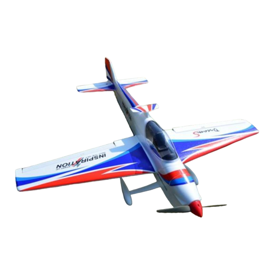
- Page 1 Dream-S F3A 50E Kit Specifications Wingspan:54.3 in (1380mm) Length:58.2 in (1480mm) Flying Weight: 2150g...
- Page 2 Dear Customer, Congratulations on your purchase of Dream-S F3A 50E Kit from Value Hobby. We thank you for your generous support, and hope you enjoy your new airplane. At Value Hobby, we hope to offer competitive prices, good performance, and products that you can setup and use with ease.
- Page 3 Before Starting Assembly Unpack your airplane and examine the components. Check for damage of any kind. If you see any damage, please contact Value Hobby immediately. Airframe Parts 1. Fuselage 2. Right and left wing 3. Rudder 4. Carbon fiber tube 5.
- Page 4 9. Leading gear wire 10. Foam safe glue 11. Small Philips screwdriver 12. Rudder connector 13. Control horn clip 14. Control horn 15. Control horn screw 16. Leading gear set 17. Fixed plate 18. Landing gear plate 19. Wheel 20. Motor mount set 21.
-
Page 5: Recommended Equipment
RECOMMENDED EQUIPMENT Product Quantity FrSky Taranis Q X7 Transmitter FRY-RC-5938 Power HD 1501MG Metal Gear Standard Servo PHD-SV-0370 GForce G32 Brushless Outrunner Motor XYH-MT-0177 Hobbywing Skywalker 80A ESC HWG-SC-4447 GForce Elite Series 4000mAh 4S LiPO FLM-LP-2202 Gemfan 13x 6.5 Prop GFH-MP-2951 Universal 26AWG Light-Weight Servo Y-Harness VHB-AC-5570... - Page 6 Elevator Control Horn Installation. Aileron Control Horn Installation. Secure the white control horn on the elevator Secure the white control horn on the aileron with two M2.5*16mm self-tapping screws. with two M2.5*16mm self-tapping screws. Connect control horn clip wire to the servo on Connect control horn clip to the servo on the the elevator.
- Page 7 Insert the rudder into the slot on the fuselage. Secure a control horn onto the rudder with two M2.5*16mm self-tapping screws. Connect the control horn to the control horn of fuselage. Secure landing gear foam cover on the leading gear with foam safe glue. Repeat the previous steps for the other leading gear.
- Page 8 Servo Assembly. Secure two servos on the servo plate in the fuselage. Install the right and left wing on the fuselage. Connect the servos to the push rod. Insert the two wooden wing locking plates into the pre-cut slot in the fuselage. This is lock the wings in place.
- Page 9 Connect the ESC to the motor. Use foam safe glue to secure the fuselage wing on the fuselage. Secure the cowling to the fuselage with four M2.5*25mm self-tapping screws. The CG should be 135mm (5.3-5.4in) from the leading edge of the wing. Install the propeller to the motor.
Need help?
Do you have a question about the Dream-S F3A 50E and is the answer not in the manual?
Questions and answers