Table of Contents
Advertisement
Quick Links
Advertisement
Table of Contents

Related Manuals for PCE Instruments PCE-CPC 50


Summary of Contents for PCE Instruments PCE-CPC 50
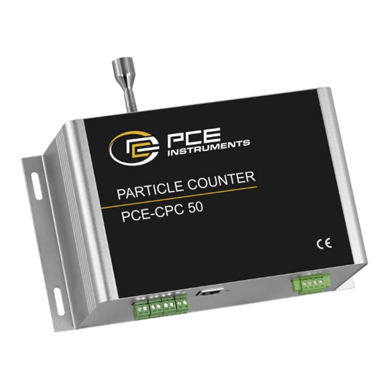
- Page 1 User Manual Cleanroom Particle Counter PCE-CPC 50...
-
Page 2: Working Principle
Description The PCE-CPC 50 online particle counter adopts the principle of optical scattering, which can accurately detect and calculate the number of suspended particles of different particle sizes in the air per unit volume. It can output the particle count of 6 channels of 0.3μm, 0.5μm, 1.0μm, 2.5μm, 5.0μm and 10μm at the same time (the default unit is pcs/m³, can be switched to pcs/L;... -
Page 3: Specification
Specification Cleanroom Particle Counter PCE-CPC 50 Specification Operating principle Light Scattering Detect particle diameter range >0.3μm, >0.5μm, >1.0μm, >2.5μm, > 5.0μm, >10μm <100pcs/l: ±30pcs/L >100pcs/L: ±30% of reading Condition: 0C ~ 40C,50+10%RH Measurement error (0°C ~ 40°C, 50 ±10%RH. Reference instrument TSI 9306. TSI 9306 count efficiency 50% @ 0.3 µm and 100% for particles >0.45 µm) - Page 4 Product Appearance and Pin Definition Function 1. Product dimensions (unit: mm, tolerance: ±2 mm) 2. Pin Definition Diagram Interface2 Interface3 Interface1 Reset Button Description Connector: Power terminal (+12VDC) KF2EDGRM-3.81-6P- 14-curved needle Interface 1 Power terminal (GND) Insertion: KF2EDGKM-3.81-6P- Communication interface (RS485_TB) Communication interface (RS485_TA) Connector: Interface 2...
- Page 5 Interface 3 Connector: I2 - I2 Negative pole KF2EDGRM-3.81-6P- 14-curved needle I3 + I3 Positive pole Insertion: >2.5um channel KF2EDGKM-3.81-6P- I3 - I3 Negative pole I4 + I4 Positive pole >5.0um channel I4 - I4 Negative pole 4 / 23...
-
Page 6: Installation Instruction
Installation Instruction When this product is installed and used in the system, the air flow of the air inlet and air outlet should be guaranteed to be smooth; in order to avoid the dust deposition on the surface of the sensitive device during use, which will affect the test accuracy of the sensor, it is recommended to install the sensor in the following way. -
Page 7: Precautions For Use
Precautions for Use ※ The instrument is forbidden to be used in environments with high dust concentration, environments containing moisture, oil and corrosive substances, and environments with high temperatures exceeding the allowable use. ※ Do not block the air inlet and outlet to avoid damage to the air pump. ※... -
Page 8: Communication Protocol
Communication Protocol 1 Protocol overview 1.1 Serial RS485 communication protocol 1) The data of this protocol are all hexadecimal data. For example, "46" is [70] in decimal. 2) [xx] is single-byte data (unsigned, 0-255); double-byte data high byte is in front and low byte is behind. 3) Baud rate: 9600b/s;... - Page 9 Table 1: Input Registers Data No. Address Definition Explanation Version No. (Enlarge 100) Reserve Reserve The number of particles >0.3μm ≥0.3μm particle quantity high byte The number of particles >0.3μm ≥0.3μm particle quantity low byte The number of particles >0.5μm ≥0.5μm particle quantity high byte The number of particles >0.5μm ≥0.5μm particle quantity low byte...
- Page 10 Table 2: Holding Registers Data No. Address Definition Explanation Reserve Reserve Address setting register Slave address (1-247) Reserve Reserve Reserve >0.3μm particles user coefficient Reserve >0.5μm particles user coefficient Reserve >1.0μm particles user coefficient Reserve IR10 >2.5μm particles user coefficient Reserve IR11 >5.0μm particles user coefficient...
-
Page 11: Command Example
6 Host communication protocol format Function code description The PCE-CPC 50 supports the following function codes: 0x03: read holding register 0x04: read input register 0x06: write a single register 7 Command example Application conditions 1) Assuming a single sensor. 2) All data are hexadecimal data, and DFX nee to be converted to decimal when calculating data. - Page 12 Send: IP 04 00 0D 00 02 CRC16 Answer: IP 04 04 DF1 DF2 DF3 DF4 CRC16 Description: >10μm particle count = DF1*256^3+DF2*256^2+DF3*256+DF4 ( pcs/ m³) 7.2 Read real-time gas flow value Send: IP 04 00 17 00 01 CRC16 Answer: IP 04 02 DF1 DF2 CRC16 Description: Real-time gas flow value = (DF1*256+DF2)/100(L/min)...
- Page 13 Send: IP 03 00 0A 00 01 CRC16 Answer: IP 03 02 DF1 DF2 CRC16 Description: >5.0 μm particles user coefficient= (DF1*256+DF2)/10000 7.4.6 Read >10 μm particle count: Send: IP 03 00 0B 00 01 CRC16 Answer: IP 03 02 DF1 DF2 CRC16 Description: >1.0 μm particles user coefficient= (DF1*256+DF2)/10000 7.5 Read output unit Send: IP 03 00 13 00 01 CRC16...
- Page 14 >0.3μm particle count user coefficient = (DF9*256+ DF10)/10000 >0.5μm particle count user coefficient = (DF11*256+DF12) /10000 >1.0μm particle count user coefficient = (DF13*256+DF14) /10000 >2.5μm particle count user coefficient = (DF15*256+DF16) /10000 >5.0μm particle count user coefficient = (DF17*256+DF18) /10000 >10μm particle count user coefficient = (DF19*256+DF20) /10000 Device stop operation time= DF23*256+DF24 (min) Control device setting flow rate=(DF25*256+DF26)/100 (L/min)
- Page 15 Description: Device stop time = DF1*256+DF2 (min) 7.14 Modify the flow rate set by the control device (the flow rate can be set in the range of 2.0L/min – 3.5L/min) Send: IP 06 00 0E DF1 DF2 CRC16 Answer: IP 06 00 0E DF1 DF2 CRC16 Description: The modified flow rate=(DF1*256+DF2)/100 (L/min) 7.15 Set output unit Send: IP 06 00 13 DF1 DF2 CRC16...
- Page 16 4~20mA=DF2*256*256*256+DF3*256*256+DF4*256+DF5 When DF1=3, current modified channel is PM5.0, corresponding measurement range of 4~20mA=DF2*256*256*256+DF3*256*256+DF4*256+DF5 The range will automatically update the corresponding range according to the set unit. Therefore, it is recommended to confirm (query) the current output unit before setting the measurement range. After the range setting will be saved.
-
Page 17: Protocol Overview
(configurable) (CMD-168) MCU->Server /productID/deviceID/properties/report Repones to data sent by the server (CMD-101 ~ CMD-110) 3 Authentication Definition Product ID: PCE-CPC 50 deviceID: Device factory sn secureId: sifangguangdian secureKey: 123456 deviceID(device SN) var clientId = deviceID var username = secureId+"|"+ ;... -
Page 18: Modify Device Parameters Cmd-8
inputs Object Downlink message content desired Object Uplink message content messageId Otring Message Id Note: All descending instructions must contain the "messageId" and "inputs" fields; and the "inputs" field must begin with cmd field. messageId of the uplink ACK = messageId of the downlink ACK 4.2 Command List MCU->Server (Downlink) Command... -
Page 19: Parameter
TOPIC:/prodcutID/deviceID/function/invoke/reply "messageId":"1574326733176995841", "cmd": "CMD-999", "output":"success" Uplink data: Parameter Type Description Number >0.3μm particle count particles_0.3um Number >0.5μm particle count particles_0.5um particles_1.0um Number >1.0μm particle count Number >2.5μm particle count particles_2.5um Number >5.0μm particle count particles_5.0um particles_10um Number >10μm particle count String Unit (pcs/m³by default) Unit... -
Page 20: Particles_Coef_0.3Um
"cmd":"CMD-102", "desired":{ "gas_flow" : 2.83 "unit" : "L/min" 5.3 Read the particle quantity coefficient CMD-4 Description: Read the particle quantity coefficient Downlink command: Parameter Type Description topic : /prodcutID/deviceID/function/invoke "messageId":"1574326733176995841", "deviceId":"173072083110001", "timestamp":1664183717422, "functionId":"CMD4", "messageType":"INVOKE_FUNCTION", "inputs":[{"cmd":"CMD-4"}] Uplink ACK (Acknowledgement message of receiving the instruction, which informs the server that the instruction was received):... -
Page 21: Work_Stop_Time
"messageId":"1574326733176995841", "deviceId":"173072083110001", "timestamp":1664183717422, "functionId":"CMD6", "messageType":"INVOKE_FUNCTION", "inputs":[{"cmd":"CMD-6"}] Uplink ACK (Acknowledgement message of receiving the instruction, which informs the server that the instruction was received): TOPIC:/prodcutID/deviceID/function/invoke/reply "messageId":"1574326733176995841", "cmd": "CMD-999", "output":"success" } Uplink data : Parameter Type Description Available to set, unit is minute. work_stop_time Number-Shaping number Cannot set it to be 0, otherwise the setting value is invalid. -
Page 22: Table Of Contents
"cmd": "CMD-107", "desired":{ "sn" : "123456789", "sw_version" : "xxx" 5.6 Modify device parameters CMD-8 Description: Modify device parameters Downlink command: Parameter Type Description >0.3μm particle count user coefficient, range 1000~65000,10000 times particles_coef_0.3um Number larger, actual coefficient is 0.1~6.5 >0.5μm particle count user coefficient, range 1000~65000,10000 times particles_coef_0.5um Number larger, actual coefficient is 0.1~6.5... - Page 23 5.7 Automatically report the data periodically CMD-168 The device will automatically report data periodically without the server sending request data packets The automatic report period is the intermittent operation period (set by CMD-8). After one working period is complete, the automatic report is uploaded once Uplink data list: Parameter Type...
- Page 24 For countries outside the EU, batteries and devices should be disposed of in accordance with your local waste regulations. If you have any questions, please contact PCE Instruments. PCE Instruments contact information...
Need help?
Do you have a question about the PCE-CPC 50 and is the answer not in the manual?
Questions and answers