Table of Contents
Advertisement
Quick Links
Advertisement
Chapters
Table of Contents

Related Manuals for German pool HTB-P225


Summary of Contents for German pool HTB-P225
- Page 1 Multi-Purpose Bathroom Heater HTB-P225 360° Multi-Oscillation Fan RHS-126 Online Warranty Registration Please read these instructions and warranty information carefully before use and keep them handy for future reference. U S E R M A N U A L...
- Page 2 請即進行保用登記! 有關保用條款細則,請看說明書最後一頁。 Please register your warranty information now ! For Warranty Terms & Conditions, please refer to the last page of this user manual.
-
Page 3: Table Of Contents
Table of Contents Warnings & Safety Precautions Product Structure Installation Instructions Operation Instructions Cleaning & Maintenance Technical Specification Warranty Terms & Conditions... -
Page 4: Warnings & Safety Precautions
German Pool. If the power cord is damaged, it must be replaced by a professional technician of the manufacturer, its repair department or similar department. -
Page 5: Product Structure
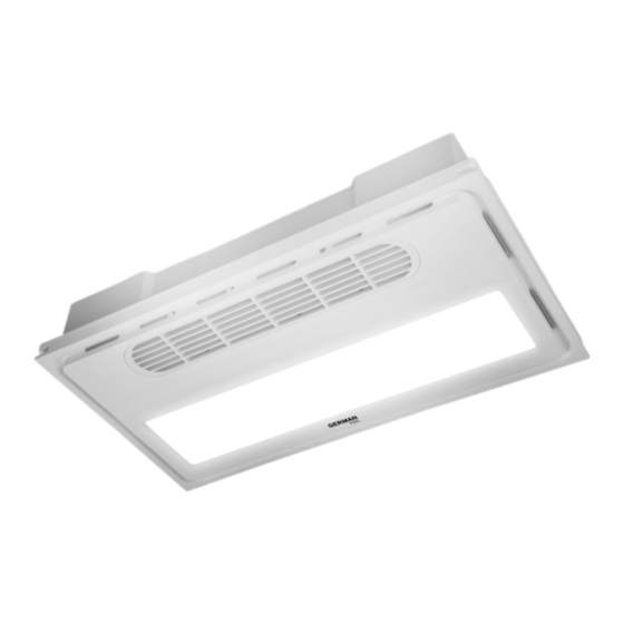
Product Structure Air Outlet Grille Display Panel Lamp Main Body Facsia Air Exhaust Vent Ventilation Ventilation Window Pipe Stabilizing Frame Suspender Kit x 4... -
Page 6: Installation Instructions
Installation Instructions Preparation Before Installation This product must be installed together with ventilation pipes. The following preparations must be done indoors before installation: 1. Drill An Air Vent Hole Confirm the location for an air vent hole on the wall (air vent hole should be located above the suspended ceiling and slightly lower than this product’s exhaust vent, to avoid condensation inside the ventilation pipe backflowing into the product), and drill a round hole of diameter Ø100mm. - Page 7 Installation Instructions Installation Referential Diagram If ventilation window can be installed on the wall’s exterior side, please install according to the diagram below: Ventilation Window Wall Hole Diameter Ø 100mm If ventilation window cannot be installed on the wall’s exterior side, please install according to the diagram below: Shape and size of wall hole (trace the outline of the ventilation window on wall if necessary)
- Page 8 Installation Instructions Installation Location To optimize heating effect, this product should be installed on the ceiling right above the bathtub or shower stall. After installation, this product must be 2.3~2.5m above the floor, too high or too low will affect product effectiveness. This product must be installed at least 250mm away from the wall. Note: •...
- Page 9 Installation Instructions Sit the main ceiling keel into the nook of the suspension bracket, then place the triangle keel bracket onto the main ceiling keel and slide it to the proper position. Thread the triangular keel through the triangular keel bracket. Main Ceiling Keel Suspension Bracket...
- Page 10 Installation Instructions B. Gypsum Board Suspended Ceiling Installation Method Mark and cut a hole on the gypsum board according to the actual size of the outer edge of the stabilizing frame that came with the product. Gypsum board cutout Stabilizing frame Normally, the cutout should be approximately 602x302mm, but slight deviation may occur, therefore the cutout should be made according...
- Page 11 Installation Instructions Attach one end of the ventilation pipe onto the wall opening. Place the main unit onto the opening of the gypsum board, attach the other end of the ventilation pipe on to the main unit’s air exhaust vent. Loop the stabilizing frame over the main unit onto the gypsum board, and secure the frame onto the main unit with M4x12 self-tapping screws..
- Page 12 Installation Instructions C. Ceiling Mounting Mark and cut a hole on the gypsum board according to the actual dimensions of the outer edge of the stabilizing frame that came with the product. Gypsum board cutout Stabilizing frame Normally, the cutout should be approximately 602x302mm, but slight deviation may occur, therefore the cutout should be made according to the actual size of the stabilizing frame on site.
- Page 13 Installation Instructions Pass the product through the gypsum board cutout hole, and attach the pre-installed exhaust duct onto the air exhaust vent of the main unit, and plug in the power cord. Align the main unit with the stabilizing frame and secure with 4 M4x12 self-tapping screws. Lower side of Stabilizing M4x12...
- Page 14 Installation Instructions Installing The Remote Control • Installing the remote control holder: secure the holder onto the embedded bottom box with coun- tersunk screws, or drill two holes on the wall 60mm apart, and secure the holder onto the wall with wall plugs and self-tapping screws.
-
Page 15: Operation Instructions
This will prolong the lifespan of the product. • During use, if any abnormality occurs, disconnect the power source immediately and contact German Pool Customer Service & Repair Centre. • DO NOT use dimmer switch with this product’s lighting. - Page 16 Operation Instructions Button Description • Press this button and product enters standby state. • All functions will turn off except for the lamp and mood light. • When user presses this button while product is in running in WARM function, the motor fan will continue to run for an extra 15 seconds then turn off.
-
Page 17: Cleaning & Maintenance
Operation Instructions Button Description • Press this button to turn on AUTO mode. • In AUTO mode, the product will automatically run according to the sequence below: • WARM or FAN for 30 min > FAN for 15 sec > VENT. for 5 min. When AUTO sequence is finished, product will automatically return to standby state. -
Page 18: Technical Specification
Technical Specification Model HTB-P225 Voltage 220 V Frequency 50 Hz Power 2480 W Protection Rating IPX2 Product Dimensions (H)100 (W)600 (D)300 mm Net Weight 4.8 kg • Specification is subject to change without prior notice. • If there is any inconsistency or ambiguity between the English version and the Chinese version, the Chinese version shall prevail. - Page 19 目錄 警告及注意事項 產品結構 安裝說明 使用說明 清潔與保養 技術規格 保用條款 P.19...
-
Page 20: 警告及注意事項
警告及注意事項 警告! 使用本產品前,請仔細閱讀所有說明。 • 本產品只限家居室內日常使用,如產品作任何商業、工業、出租或其他用途,保用證即告失 效。 • 請勿讓兒童或身體有殘障、精神不健全及對本產品缺乏經驗或知識的人士單獨使用本產品;如 需使用,必須要在負責任的成年人監管下方可使用。 • 應照顧好兒童,確保他們不會玩耍本產品。 • 無成年人監管下,勿讓兒童清潔及維護本產品。 • 使用前,請先檢查所有電壓是否與本產品標籤上的電壓相符。 • 如果電源線損壞,為免發生意外,電源線必須由廠方、廠方指定的維修中心或同等合格的技術 人員進行更換。 • 清潔或檢查本產品前,必須先關機及拔掉插頭。 • 請聯繫德國寶授權的技術人員進行維修或保養本產品。 1. 本產品未經安裝嚴禁使用;本產品需要吊頂安裝在室內的水平天花板上的,嚴禁安裝在傾斜的 平面上;帶製暖模組的產品必須安裝在離地面高度2.3- 2.5米之間:必須遠離噴淋頭或滲水的 地方;嚴禁將本產品直接置於電源插座的下面。 2. 帶製暖模組的產品必須與固定佈線電纜相連接,電纜必須安置在合適的佈線槽中,電纜線徑不 小於1.5平方毫米。電源進線必須安裝一個觸點斷開距離至少3毫米、額定電流16A以上的雙極 斷開電源開關裝置,將本產品和電源分開;嚴禁將本產品與其他電器共用一個電源插座;電源 插座必須有≥16A的容量。 3. 本產品安裝時,嚴禁照明燈與調光器串聯使用。 4. 嚴禁將本產品靠近窗簾和其他可燃材料安裝,使用過程中嚴禁覆蓋本產品。 5. 在電器安裝時必須將所配開關固定在牆上,必須讓浴缸或淋浴區的人不能夠觸及到開關和其他 控制器,開關固定位置應有效防止水濺。 6. 本產品在使用過程中或使用後未冷卻時,嚴禁直接接觸產品,以免燙傷。 7. 本產品必須由專業電工嚴格按照接線圖接線;並使用220V/50Hz標準電源。... -
Page 21: 產品結構
產品結構 出風口 顯示屏 照明燈 機身 面蓋 排風口 排風窗 排風管 吊杆配件 x 4 主機固定框 P.21... -
Page 22: 安裝說明
安裝說明 安裝前的準備工作 本產品必須安裝排風管排氣,在安裝本產品前,室內必須做好以下準備工作: 1. 開排風孔 確定牆壁上排風孔的位置(應在吊頂上方略低於本產品排風口,以防止排風管內結霜水倒流 入本產品),在該位置開一個直徑Ø100mm的圓孔作排風孔。 2. 安裝排風窗 將排風管的一端套上排風窗,另一端從牆壁外沿排風孔伸入室內,將排風窗固定在外牆排風 孔處,排風管與排風孔的空隙處用水泥填封。 牆 排風管 排風窗 吊頂 水泥 注意: 本產品安裝位置中心與外牆排風孔的距離嚴禁超出排風管的長度,排風管規格如下: • 排風管長度3m • 排風管口徑Ø100mm P.22... - Page 23 安裝說明 安裝參考圖 適宜在牆壁外安裝排風窗的用戶請按下圖進行安裝: 排風窗 牆壁開孔 直徑Ø100mm 不適宜在牆壁外安裝排風窗的用戶請按下圖進行安裝: 牆壁開孔形狀及尺寸 (可按排風窗外輪廓劃線) 排風窗 直徑Ø120mm 注意: • 排風窗固定在牆壁上時,必須保持其印有「向上」字樣的一端朝上安裝,否則將失去作 用。 • 排風管嚴禁與燃氣熱水器排氣管接入同一煙道,以防危險氣體進入室內。 P.23...
- Page 24 安裝說明 確定產品安裝位置 為了取得最佳的製暖效果,本產品應安裝在浴缸或淋浴房中央正上方,安裝完畢後,本產品 離地面的高度應在2.3-2.5米之間,過高或過低都會影響使用效果;本產品與牆壁距離不少於 250毫米。 注意: • 安裝前,請認真閱讀本說明書。 • 安裝前必須切斷電源,本產品不得直接置於電源插座下面。 • 本產品被覆蓋或不正確的放置會引起火災危險,故不得利用帶有可自動接通電源的程式 器、定時器或任何其他裝置來使用本產品。 • 安裝時,必須在供電線路中安裝其觸點開距不少於3毫米的「電源全極開關」以用於 接通或斷開電源,其額定負載能力不少於250V-16A,且安裝在浴室外側方便操作的地 方。 A. 吊頂安裝方法 安裝龍骨 • 依據吊頂高度,將吊杆裁剪出適當長度。 • 將龍骨掛鉤與吊杆一端固定,在天花板的適當位置打孔,將吊杆帶有膨脹螺栓的一端與 天花板固定。 吊杆 膨脹螺栓 吊杆過孔 龍骨掛鉤 擰緊螺帽固定 P.24...
- Page 25 安裝說明 將主龍骨卡入龍骨掛鉤的卡槽內,再將三角龍骨吊件勾架於主龍骨,三角龍骨吊件可沿主龍 骨調節位置,最後將三角龍骨套入三角龍骨吊件的卡口內。 主龍骨 龍骨掛鉤 三角龍骨吊件 三角龍骨 主機安裝 • 將4個安裝卡扣用隨附的M4螺栓和螺帽固定在箱體相應的部位。 • 將已經安裝好卡扣的主機倒扣在龍骨上,使四周的卡扣鎖緊龍骨。 • 卸下接線盒蓋板螺釘和壓線板螺釘,請專業人員按照產品接線圖連接好電源線,再安裝 上壓線板和接線盒蓋板,裝好螺釘。 分別將主機和面板的照明連接頭和顯示器連接頭連接好,進行通電試驗,主機功能運行正常 後,再扣上面板,注意面板出風口要對準主機出風口。 螺帽 安裝卡扣 螺栓 P.25...
- Page 26 安裝說明 B. 石膏板吊頂安裝方法 1. 根據主機固定框(跟機附送)外沿實際尺寸在石膏板上劃線開孔。 石膏板開孔 主機固定框 一般為602mm×302mm,具體偏差按 主機固定框實際尺寸現場劃線。 2. 根據主機上的吊桿配件位置預先裝好吊桿(M8螺桿),吊桿底端離石膏板面約30mm。 石膏板上方 335mm 30mm 3. 安裝吊桿配件,通過上下螺母調節適當高度:吊桿配件底端離石膏板約23mm。 23mm P.26...
- Page 27 安裝說明 4. 將主機穿過石膏板開孔,將預先接在牆上的排風管固定在主機的排風口上,然後將主機 卡在吊桿配件上,將主機固定框穿過主機卡到石膏板上,用M4×12自攻螺絲固定好。 M4×12 石膏板下方 主機固定框 自攻螺絲 石膏板上方 M4×12 自攻螺絲 主機放上石膏板後,先連接好排風管 並用抱箍固定好。 5. 最後將面板與主機的連接線先對應連接好,然後將面板扣入主機固定框中。注意面板出 風口要對準主機出風口。 主機與面板出風口要對準安裝 P.27...
- Page 28 安裝說明 C.天花安裝方法 1. 根據主機固定框(跟機附送)外沿實際尺寸在石膏板上劃線開孔。 石膏板開孔 主機固定框 一般為602mm×302mm,具體偏差按 主機固定框實際尺寸現場劃線。 2. 將主機固定框卡入石膏板開孔,用4顆沉頭自攻螺絲固定。 3. 將主機穿過石膏板開孔,將預先接在牆上的排風管固定在主機的排風口上,把主機電源 線接好後將主機和主機固定框對齊,用4顆M4×12自攻螺絲固定好。 M4×12 石膏板下方 主機固定框 自攻螺絲 M4×12 自攻螺絲 P.28...
- Page 29 安裝說明 4. 最後將面板與主機的連接線先對應連接好,然後將面板扣入主機固定框中。注意面板出 風口對準主機出風口。 主機與面板出風口要對準安裝 安裝遙控器 • 安裝遙控器滑板:可通過沉頭螺栓把遙控器滑板固定在預埋底盒上;或者在牆壁上鑽兩 個間距為60mm的孔,通過膨脹管和自攻螺絲把遙控器滑板固定在牆面上;也可在遙控 器滑板背面黏貼不乾膠,黏附固定在平整的牆面上。 • 安裝電池:扣開遙控器背面的後蓋,按正負極安裝兩節AAA號電池,蓋上後蓋,按動遙 控器的各個功能鍵進行測試,確認產品的各項功能正常。 後蓋 電池 遙控器 注意: • 遙控器在出廠前已完成對碼,無需重新對碼,可直接使用。 • 若按遙控器後產品沒有反應,請檢查電池電量是否枆盡。 • 如更換電池後遙控器仍無法操作,請按以下方法重新對碼: 1. 切斷本產品電源,等待1分鐘後重新開電源。 2. 將遙控器置於本產品下方,長按OFF鍵約5秒,直至聽到本產品發出蜂嗚器聲響一 聲,表示對碼成功。 P.29...
-
Page 30: 使用說明
使用說明 機身顯示屏 低檔暖風 高檔暖風 溫度顯示 換氣指示燈 吹風指示燈 指示燈 指示燈 接通電源後,根據您的需要來選擇開啟或關閉風暖、照明、吹風、換氣各功能鍵,各功能鍵 均相互獨立。 注意: • 使用暖風功能後,建議使用吹風功能運行約15秒,使產品內的熱量完全散發出來,以增 強產品的使用壽命。 • 在使用過程中如發現異常情況,應迅速斷開電源,聯絡德國寶客戶服務及維修中心。 • 照明燈嚴禁與調光器串聯使用。 • 老人、小孩和行動不便人員必須在家人指導下使用本產品。 • 使用時嚴禁覆蓋本產品。 遙控器 P.30... - Page 31 使用說明 按鍵 說明 .按此鍵後產品進入待機狀態。 .除照明及夜燈外,其他所有功能關閉。 待機鍵 .如在使用暖風功能期間按此鍵,風機將延時15秒後關閉。 .按此鍵關閉自動模式或烘乾模式。 .按此鍵開啟照明燈;再按一次關閉照明燈。開啟此功能後,即使120分 照明鍵 鐘內無任何操作,功能亦不會自動關閉。 .按此鍵開啟夜燈;再按一次關閉夜燈。開啟此功能後,即使120分鐘內 夜燈鍵 無任何操作,功能亦不會自動關閉。 .按此鍵一次開啟高檔暖風功能,高檔暖風指示燈常亮。開啟此功能後, 120分鐘內無任何操作,產品會自動返回待機狀態。 暖風鍵 .按第二次切換至低檔暖風功能,低檔暖風指示燈常亮。開啟此功能後, 120分鐘內無任何操作,產品會自動返回待機狀態。 .按第三次關閉暖風功能,風機延遲15秒後關閉,暖風指示燈關閉。 .按此鍵開啟或關閉換氣功能。開啟此功能後,換氣指示燈常亮。 換氣鍵 .如開啟換氣功能後,120分鐘內無任何操作,產品自動返回待機狀態。 .按此鍵開啟或關閉吹風功能。開啟此功能後,吹風指示燈常亮。 吹風鍵 .如開啟吹風功能後,120分鐘內無任何操作,產品自動返回待機狀態。 .按此鍵開啟自動模式。 .在自動模式下,產品按照以下順序自動運行: 暖風或吹風30分鐘 > 吹風15秒 > 換氣5分鐘,程序結束後產品自動返 自動鍵 回待機狀態。 .如室溫低於25° C,運行高檔暖風;如室溫於25-34° C之間,運行低檔 暖風;如室溫高於35° C,運行吹風功能。 .按此鍵開啟烘乾模式。 .在烘乾模式下,產品按照以下順序自動運行: 烘乾鍵 低檔暖風20分鐘 > 吹風15分鐘 > 換氣5分鐘。循環運行3個週期後產品 自動返回待機狀態。...
-
Page 32: 清潔與保養
清潔及保養 警告! 在維修或保養前,必須先關機並切斷電源。 • 應在本產品充分冷卻的情況下進行清潔,卸下面板,用沾上中性清潔劑的軟布輕輕擦拭。 • 嚴禁讓水進入風輪或發熱塊、摩打。 警告! 嚴禁使用腐蝕性溶劑清潔本產品。 技術規格 HTB-P225 型號 電壓 220 V 50 Hz 頻率 2480 W 功率 IPX2 防水等級 (H)100 (W)600 (D)300 mm 產品尺寸 4.8 kg 淨重 • 產品規格及設計如有變更,恕不另行通知。 • 中英文版本如有出入,一概以中文版為準。 • 本產品使用說明書以www.germanpool.com網上版為最新版本。 P.32... -
Page 33: Warranty Terms & Conditions
- the serial number is modified, damaged or removed from the product. - 機身編號被擅自塗改、破壞或刪除。 4. German Pool will, at its discretion, repair or replace any defective part. 4. 總代理有權選擇維修或更換配件或其損壞部份。 5. This warranty will be void if there is any transfer of 5. - Page 34 Fax:+853 2875 2661 HONG KONG TOP BRAND TEN YEAR ACHIEVEMENT AWARD © All rights reserved. Copying, reproducing or using the contents of this manual is not allowed without prior authorization from German Pool, violators will be prosecuted. www.germanpool.com HTB-P225-M-23(1.1) P.34...
Need help?
Do you have a question about the HTB-P225 and is the answer not in the manual?
Questions and answers