Table of Contents
Advertisement
Quick Links
Advertisement
Table of Contents

Related Manuals for IGS BAOHUI HYPER CROSS


Summary of Contents for IGS BAOHUI HYPER CROSS
- Page 1 M200SERIES SEM-2106-01-4...
- Page 2 Procedures not described in this Manual or marked as ‘to be carried out by Site out by personnel without the necessary skill or technological experience. Work electrocution dangerous procedures which should only be carried out by professionals with the appropriate specialised knowledge.
- Page 3 disposed of in accordance with the directive at the end of their useful life. The symbol shown below will be placed on all products manufactured from 13th August 2005, which indicates this product must NOT be disposed of with other normal waste. For more information on Approved Authorised Treatment Facilities (AATF), please consult your local government authority.
-
Page 4: About This Manual
Please carefully store this user manual at where it can be easily accessed and read. Disclaimer IGS makes no warranty, expressed or implied, including but not limited to any implied warranties of the correctness and completeness of this document. IGS also makes no change without notice. -
Page 5: Safety Precautions
If electrical cords are damaged, replace new ones with your local distributor. Do not use fuses and parts other than those designated by IGS. To avoid electric shocks or short circuits: Do not touch plugs with wet hands. -
Page 6: Installation Location
Safety Precautions Ordinary Without the permission from our designated personnel, do not disassemble, change or CAUTION remodel our products. Be sure to operate this product according to the instructions of this manual. Any inappropriate operation would damage this product and threaten the personal safety of players as well as onlookers. -
Page 7: Table Of Contents
Table of Contents Table of Contents 4.6 Income Data .............. 48 About This Manual ......1 4.6.1 Daily Income ..............49 Safety Precautions ......2 4.6.2 Monthly Income ............50 4.6.3 Total Report ..............51 Table of Contents ......4 4.7 System Reset ............52 4.7.1 Reset Income Data ............ -
Page 8: Quick Installation
Quick Installation Quick Installation Connection Setting You can enter Connection Setting to set up the group number and ID of the machine. Enter Main Menu 2 System Setting , and appoint all Note: The recommended ID value settings for the machine, from left to right, are: 1P, 2P, 3P, 4P. -
Page 9: Setting Other Related Items
Quick Installation Setting Other Related Items Setting other related items (recommended): Enter Main Menu 2 System Setting , and set the machines to be connected at the same time. Enter Main Menu 2 System Setting Setting to set up the location and name of the store. Enter Main Menu 3 Game Setting... -
Page 10: Introduction Of The Cabinet
Introduction of the Cabinet Introduction of the Cabinet 1.1 List of the accessories After your purchase of this product, check if the following parts are all included. If any part is missing or damaged, contact your local distributor. Name of Accessories Picture Quantity Power cord... - Page 11 Introduction of the Cabinet Name of Accessories Picture Quantity Vehicle body 2 PCS Coin box 1 PCS Screen box (left) 1 PCS Screen box (right) 1 PCS Machine name light box 1 PCS List of the accessories...
- Page 12 Introduction of the Cabinet Name of Accessories Picture Quantity Machine name light box 1 PCS Machine name light box bracket A 1 PCS Machine name light box bracket B 1 PCS Camera character acrylic (left) 1 PCS Camera character acrylic (right) 1 PCS Upper decorative PVC foam board 1 PCS...
- Page 13 Introduction of the Cabinet Name of Accessories Picture Quantity Upper decorative PVC foam board 1 PCS (right) Cabinet connection bracket A cover 2 PCS Cabinet connection bracket A 4 PCS Cabinet connection bracket B 1 PCS Cabinet connection bracket C 1 PCS PVC foam board Fixed 4 PCS...
-
Page 14: An Overview Of The Cabinet
Introduction of the Cabinet 1.2 An Overview of the Cabinet Viewed from the top, front and side An Overview of the Cabinet... - Page 15 Introduction of the Cabinet 2707 /mm An Overview of the Cabinet...
-
Page 16: Name Of The Parts
Introduction of the Cabinet 1.3 Name of the Parts The outward of the cabinet Cardboard (Left) Hypercross light box Decorative acrylic (Left) 42"LCD Cardboard (Right) Acrylic board Decorative acrylic 4'' Speaker (Right) Springboard Vehicle body Central connector bracket Vent 8'' Speaker light acrylic Name of the Parts... - Page 17 Introduction of the Cabinet The outward of the cabinet Light box Springboard maintenance door maintenance Maintenance Door (Up) compressor Maintenance maintenance Door (Down) Movable caster Power Inlet Air compressor caster inlet Motherboard POWER Transformer(Steering handle bar) Voltage stabilizer Name of the Parts...
- Page 18 Introduction of the Cabinet The outward of the cabinet Solenoid valve placement area Throttle lever (Left) Throttle twist Button grip Select Keys Seat Sensor Steering handle bar Vehicle side light Tail light Track Lights (Side) Track Lights (Back) Ski gradient Light Dust shield Platform guide light...
- Page 19 Introduction of the Cabinet The outward of the cabinet Coin acceptor Control panel Counter Volume Coin funnel Test Control panel Service Coin box Air compressor Airbag regulator Fluid control valve Manual valve Water collection tray Name of the Parts...
- Page 20 Introduction of the Cabinet 1.4 Specification of the Cabinet Category Item Specification Size of the cabinet (W)2710mmX (D)2220mmX (H)2300mm Concrete item Weight 930KG Power AC110V/220V(To conform to local voltage) 1P Cabinet: 430W Standby Power 2P Cabinet: 430W Power Air Compressor: 330W 1P Cabinet: 830W Maximum Power 2P Cabinet: 830W...
- Page 21 Introduction of the Cabinet Category Item Specification Power AC 110V~220V Helicoid Fan Power DC12V Type Screen Size 42 inches Power AC110V/220V (To conform to local voltage) Speaker Size/Resistance/Power Bass Speaker 8 inches 4 Air Compressor Power AC110V/220V (To conform to local voltage) Operating temperature ~ 40 Environment...
-
Page 22: Machine Installation
Machine Installation Machine Installation 2.1 Transporting or Moving the Cabinet then connect the wires. When you transport, move and choose where to install, make sure the following guidelines are followed: Reminders for Transporting When transporting this product with a forklift, make sure you exert the point of application to avoid accidents or damages to the cabinets. -
Page 23: Disassembly And Reassembly Diagram For Transport
Machine Installation 2.2 Disassembly and Reassembly Diagram for Transport 1. According to the diagram, assemble the vehicle body and the screen box. (1P and 2P cabinet can be assembled in the same way.) a. decorative acrylic b. screen box d. vehicle body About the decorative acrylic: Install the decorative acrylic on the When the vehicle body and the screen... - Page 24 Machine Installation 4. Install the springboard to central connector bracket according to the diagram. 5. Install the machine name light box to the springboard according to the diagram. a. light box bracket b. light box c. wire cover Disassembly and Reassembly Diagram for Transport...
- Page 25 Machine Installation coin box part screen 1P screen 2P 5557-10P 5559-10P 5559-10P 5557-10P tag:pic14(1)/ tag:pic14(2)/ tag:pic14(3)/ tag:pic14(1)/ coin box connector coin box connector1P coin box connector2P coin box connector YL-6P-P YL-6P-R YL-6P-R YL-6P-P tag:pic13(1)/volume tag:pic13(3)/volume tag:pic13(3)/volume tag:pic13(2)/volume board connector board connector board connector board connector blue 5557-4P...
-
Page 26: Fastening The Cabinet
Machine Installation 2.3 Fastening the Cabinet Fasten the cabinet with the leg leveler: Counterclockwise turn the leg leveler till a distance of at least 5mm is kept between the Fastening the Cabinet... -
Page 27: Game Description
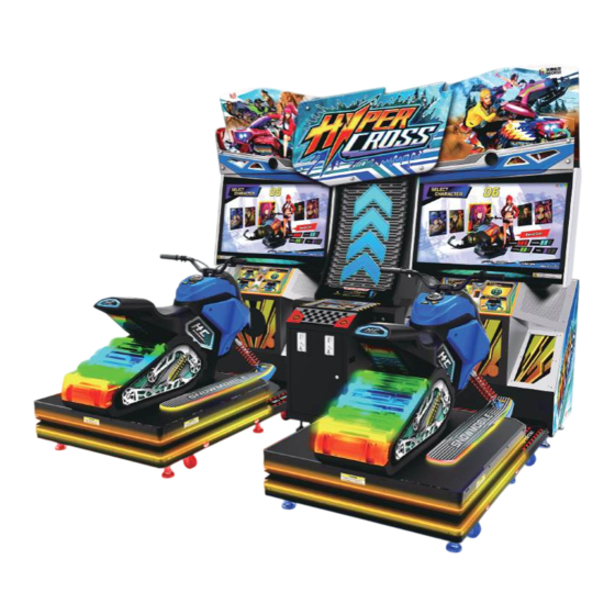
Game Description Game Description 3.1 Game Introduction Hypercross is a racing arcade game. By using motion platform, fans, vibration, and the force feedback system, the game simulates racing actions, such as collisions, turning, and accelerating, and thus providing players with vivid snowmobiling experiences. Players will ride on snowmobiles and travel over all kinds of terrain, such as water, sand, snow. - Page 28 Game Description On the page of upgrade, turning steering handle bar to select a section to upgrade. Upgrade sections: Top Speed Increase maximum speed. Twist the throttle twistgrip to accelerate. Handling Make turns easier. Boost Increase boost speed. When a section is upgraded to the maximum, the word MAX will show up, suggesting the section can no longer be upgraded .
-
Page 29: Instruction Of The Game Display
Game Description 3.4 Instruction of the Game Display Connection Setting Game Version Number will appear on this page Coin(s) ID of the machine Total Time Rank Distance Left Nitrogen RPM / KPH Coin(s) Instruction of the Game Display... -
Page 30: Using The Operator Settings
Using the Operator Settings Using the Operator Settings 4.1 Menu Structure I/O Test Coin Left Brake Test Steering Handle Bar Service Motion Stop Button Hardware Test Start I/O Test Up Down Screen Test Seat Sensor Sound Test Throttle twistgrip Lamp Test Connection Test Sound Test Camera Test... -
Page 31: Main Menu Operation
Using the Operator Settings 4.2 Main Menu Operation In the menu, follow the steps below to navigate: Use the Up and the Down button to select the options, the currently selected option is marked in red. Press the Start After completing the setting or testing, return to Main Menu and select 6 Exit , then press the Start button to return to the game screen. -
Page 32: I/O Test
Using the Operator Settings 4.3.1 I/O Test On the page of I/O Test functioning normally or not. Enter Main Menu 1 Hardware Test , and the screen will display as below: After you enter the page of I/O Test as explained in the chart below Application Testing method Result... -
Page 33: Screen Test
Using the Operator Settings 4.3.2 Screen Test On the page of Screen Test , you can test whether the white balance, color level, and lattice are functioning normally or not. Enter Main Menu 1 Hardware Test After entering Screen Test , the system will then process the testing, and the following On the page of Screen Test , press the Start... -
Page 34: Lamp Test
Using the Operator Settings 4.3.4 Lamp Test On the page of Lamp Test , you can test if each light is functioning normally or not. Enter Main Menu 1 Hardware Test , and the screen will display as below: Use the button and Down button to move the cursor then press the Start... -
Page 35: Connection Test
Using the Operator Settings 4.3.5 Connection Test On the page of Connection Test , you can test whether the connection functions normally. Enter Main Menu 1 Hardware Test , and the screen will display as below: Move the cursor to and press the Start button to start testing. -
Page 36: Camera Test
Using the Operator Settings After the testing is completed, move the cursor to , and press the Start button to return to Hardware Test . 4.3.6 Camera Test On the page of Camera Test , you can test if the camera functions normally. Enter Main Menu 1 Hardware Test... -
Page 37: Counter Test
Using the Operator Settings 4.3.7 Counter Test On the page of Counter Test , you can test whether the counter is functioning normally or not. Enter Main Menu 1 Hardware Test , and the screen will display as below: After you enter the page of Counter Test , insert coins to the coin slot, and the number on the right will go up as more coins are inserted. -
Page 38: Fan Speed Test
Using the Operator Settings 4.3.9 Fan Speed Test On the page of Fan speed Test , you can test whether the fan is functioning normally or not. Enter Main Menu 1 Hardware Test , and the screen will display as below: Use the button and Down button to move the cursor then press the... -
Page 39: Air Spring Test
Using the Operator Settings 4.3.11 Air Spring Test On the page of Air Spring Test , you can test whether the air spring is functioning normally or not. Enter Main Menu 1 Hardware Test , and the screen will display as below: Move the cursor and then press the Start button to test the air spring on the selected option. -
Page 40: System Setting
Using the Operator Settings While testing, a warning message will appear Caution!!The steering wheel is being tested for force feedback, put your hands away from the steering wheel . Move the cursor to and press the Start button to return to Hardware Test . -
Page 41: Time Setting
Using the Operator Settings 4.4.1 Time Setting On the page of Time Setting , you can set up your local time. Date , Time will be automatically synchronized with the server's time when connected to the server. Enter Main Menu 2 System Setting , and the screen will display as below:... -
Page 42: Connection Setting
Using the Operator Settings If the chosen country has more than one time zones, or Other is selected, the screen will automatically direct to the page of Timezone Setting . 4.4.2 Connection Setting Connection Setting , you can set the group and the ID of the machine. On the page of To connect to the machine, please set up the same group in the settings. -
Page 43: Country Setting
Using the Operator Settings Use the button and Down button to move the cursor and press the Start button to enter the sub menu. Select the , then press the Start button to set the group number of the machine. Select the , then press the Start... -
Page 44: Store Setting
Using the Operator Settings 4.4.4 Store Setting On the page of Store Setting , you can set your store name. Enter Main Menu 2 System Setting , and the screen will display as below: Use the Up , Down , Left , Right button to move the cursor and press the Start When completed, move the cursor to OK , then press the Start... - Page 45 Using the Operator Settings Move the cursor to and press the Start button to return to 2 System Setting . On the page of the throttle, brake and steering handle bar. Enter Main Menu 2 System Setting , and the screen will display as below: ■...
-
Page 46: Seat Safety Sensor Setting
Using the Operator Settings On the page of value of the air spring. Enter Main Menu 2 System Setting , and the screen will display as below: Move the cursor to the and press the Start button to start status will display on the screen. and then press Start button to return to... -
Page 47: Game Setting
Using the Operator Settings 4.5 Game Setting On the page of Game Setting , you can set up all related features of the game. Enter Main Menu 3 Game Setting , and the screen will display as below: Use the button and Down button to move the cursor and press the Start... -
Page 48: Volume Setting
Using the Operator Settings 4.5.2 Volume Setting On the page of Volume Setting , you can determine the start time of daytime and evening and set the corresponding volume. Enter Main Menu 3 Game Setting , and the screen will display as below: Move the cursor to select the Daytime(Evening) Volume Setting , then press the Start... -
Page 49: Number Of Laps And Race Time Setting
Using the Operator Settings 4.5.3 Number Of Laps And Race Time Setting On the page of Number of Laps And Race Time Setting , you can determine number of laps, and race time. Enter Main Menu 3 Game Setting Setting , and the screen will display as below: Start , and press the Start... -
Page 50: Flow Time Setting
Using the Operator Settings 4.5.5 Flow Time Setting on the page of Flow Time Setting , you can determine the duration of each process: Enter Main Menu 3 Game Setting , and the screen will display as below: Move the cursor to select the item, then press the Start button to start the process. -
Page 51: Income Data
Using the Operator Settings On the page of , you can change the acceleration which the game automatically adds to player's vehicle. Use the Up and Down button to move cursor, select Weak(Default) and press Start . The acceleration will be set to Weak , and the screen will automatically direct to Game Setting . -
Page 52: Daily Income
Using the Operator Settings 4.6.1 Daily Income On the page of Daily Income , you can check the daily revenue of each cabinet. Enter Main Menu 4 Income Data ,and the screen will display as below: Descriptions of each item are as follows: Item Description Date... -
Page 53: Monthly Income
Using the Operator Settings 4.6.2 Monthly Income On the page of Monthly Income , you can check the monthly revenue of each cabinet. Enter Main Menu 4 Income Data ,and the screen will display as below: Descriptions of each item are as follows: Item Description Month... -
Page 54: Total Report
Using the Operator Settings 4.6.3 Total Report On the page of Total Report , you can check the total revenue of each machine. Enter Main Menu 4 Income Data ,and the screen will display as below: Descriptions of each item are as follows: Item Description Coin(s) -
Page 55: System Reset
Using the Operator Settings 4.7 System Reset On the page of System Reset , you can delete the income data or set the system to default setting. Enter Main Menu 5 System Reset , and the screen will display as below: Use the button and Down button move the cursor and press the... -
Page 56: Restore Defualt Setting
Using the Operator Settings Move the cursor to Yes, reset income data. , and press the Start button to reset income data. After reset, Reset Complete will appear in green. Press Start button again to return to 5 System Reset . This function will not delete the data in Total Income . -
Page 57: Ranking Board Reset
Using the Operator Settings Move the cursor to Yes, restore default setting. , and press the Start button to reset income data. After restore, Restore Complete will appear in green. Press Start button again to return to System Reset . The settings below will be reset to default: System Setting: Connection Setting, Country Setting, Store Setting, Password Setting, I/O Game Setting: Coin Option, Volume Setting, Game Time, Battle Reward Setting, Flow Time... -
Page 58: Update Progress
Using the Operator Settings Move the cursor to Yes , and press Start button to reset ranking board. After reset, Ranking Data Restore Complete will appear in green. Press Start button again to return to System Reset . When is selected, the screen will automatically direct to the page of 5 System Reset . -
Page 59: Game Setting Defaults
Using the Operator Settings Move the cursor to Yes, clear the coin count in the bottom right corner. , and press Start button to clear the coin count. Or, select [No] to leave this page, the screen will automatically direct to the page of 5 System Reset . When you reset income data, the current coin count in attract sequence will be cleared too. - Page 60 Using the Operator Settings Default Name of the Setting Available Setting Setting Volume Setting Volume Setting 100% 0%,10%,20%…100% 100% 0%,10%,20%…100% Daytime/Evening Volume Setting Daytime/Evening Volume Setting Scene Volume Scene Volume Volume Setting Volume Setting 100% 0%,10%,20%…100% 100% 0%,10%,20%…100% Daytime/Evening Volume Setting Voice Volume Daytime/Evening Volume Setting Voice Volume...
-
Page 61: Maintenance And Repair
Maintenance and Repair Maintenance and Repair 5.1 Daily inspection To extend the life of this product, routinely maintain and inspect it. Exterior inspection Check if all warning labels are present and legible. Check the leg levellers are secure and the casters are NOT touching the ground. Check coin handling area is clear of detritus. -
Page 62: Replacing Parts
Maintenance and Repair 5.3 Replacing Parts 5.3.1 Maintenance instructions for the upper light box light strips Decorative acrylic Remove the decorative acrylic fixing screws according to the diagram. Light box cover After unscrewing the screws of the acrylic, remove the light strips for maintenance. - Page 63 Maintenance and Repair Light strips Unscrew the screws from light strip to start maintenance. Light box maintenance door the light box maintenance door. Remove the light strip securing s c r e w s a n d p e r f o r m t h e maintenance.
-
Page 64: Maintenance Instructions For The Camera
Maintenance and Repair 5.3.2 Maintenance instructions for the camera Light box maintenance door the light box maintenance door. Camera back cover hardware Remove the camera back cover hardware. R e m o v e t h e c a m e r a securing bracket and start the replacement. -
Page 65: Maintenance Instructions For The Screen Lower Light Strips
Maintenance and Repair 5.3.3 Maintenance instructions for the screen lower light strips Decorative acrylic Remove the decorative acrylic fixing screws from the screen. Remove the light strips and then begin the light Light strips strip maintenance. Replacing Parts... -
Page 66: Maintenance Instructions For The Screen
Maintenance and Repair 5.3.4 Maintenance instructions for the screen Open the rear maintenance door with the corresponding key and detach the screen cables. Rear maintenance door Remove the screen frame Remove the screen frame back Replacing Parts... - Page 67 Maintenance and Repair Remove the screen frame fixing screws and remove the screen frame back cover carefully. After replacing the screen, r e i n s t a l l t h e s c r e e n b y reversing the steps.
-
Page 68: Maintenance Instructions For The Air Vent Blowers
Maintenance and Repair 5.3.5 Maintenance instructions for the air vent blowers Acrylic on the air vent Remove the acrylic on the air vent according to the diagram. Remove the blower fixing frame. Remove and replace the blowers according to the diagram, once completed, reinstall by reversing the steps. -
Page 69: Maintenance Instructions For Bass Speaker Light Board
Maintenance and Repair 5.3.6 Maintenance instructions for bass speaker light board Remove the fixing screws from the bass speaker and remove the bass speaker mesh carefully. Bass speaker mesh Remove the light board fixing screws according to the diagram and then begin maintenance. - Page 70 Maintenance and Repair 5.3.7 Remove the fixing screws from the bass speaker and remove the bass speaker mesh carefully. Maintenance door Remove the fixing hardware side guide lights sheet metal according to the diagram. Remove the light strip fixing Light strip s c r e w s a c c o r d i n g t o t h e d i a g r a m a n d t h e n b e g i n maintenance.
-
Page 71: Maintenance Instructions For The Air Compressor
Maintenance and Repair 5.3.8 Maintenance instructions for the air compressor Open the maintenance door with the corresponding key. Maintenance door pressure of the air compressor, ensure that the pressure value is 0, and then remove the pressure regulating valve connection p i p i n g . - Page 72 Maintenance and Repair Remove the securing screws from the air compressor tray. Pull the handle of the pusher plate from the front and pull the air compressor outside t h e c a b i n e t t o c a r r y o u t maintenance.
-
Page 73: Maintenance Instructions For Machine Name Light Box Light Strips
Maintenance and Repair 5.3.9 Maintenance instructions for machine name light box light strips Remove the securing screws from machine name acrylic according to the diagram. Machine name acrylic Remove the fixing screws from the transparent PVC according to the diagram. Transparent PVC Light strips After replacing the light strips,... -
Page 74: Maintenance Instructions For Springboard Light Strips
Maintenance and Repair 5.3.10 Maintenance instructions for springboard light strips Remove the decorative PVC fixing screws according to the diagram. Remove light strips and begin maintenance. Replacing Parts... -
Page 75: Maintenance Instructions For The Airbag Solenoid Valve
Maintenance and Repair 5.3.11 Maintenance instructions for the airbag solenoid valve Remove the fixing screws from platform maintenance upper cover and remove the upper cover carefully. Platform maintenance upper cover Remove water vapor cover, a n d r e m o v e t h e s c r e w s that lock the solenoid valve in place. -
Page 76: Explosion Diagrams Of The Vehicle
Maintenance and Repair 5.3.12 Explosion diagrams of the vehicle PARTS LIST ITEM TITLE PART NUMBER PARTS LIST steering handle bar cover - A AMA-20-31610 ITEM TITLE PART NUMBER Screw M4X12L SCR_THSHS-N-M4X12L Screw M4X20L SCR_PHS-NC-M4X20L steering handle bar cover - B AMA-20-31620 MU - LED control panel MU-1191-00... - Page 77 Maintenance and Repair PARTS LIST ITEM TITLE PART NUMBER ITEM TITLE PART NUMBER Screw M6X40L SCR_THSHS-N-M6X40L Wasser M12 WASHER_D12 Screw M5X12L SCR_THSHS-N-M5X12L Spring washer M12 WASHER_S-D12 cover - R AMA-20-31523-4 Nut M12 HEX_NUT-M12 PU - A AMA-20-31523-2 magnet MAGNET-20X10MM Screw M4X8L SCR_PHS-NC-M4X8L magnet fixing bracket AMA-20-31531...
- Page 78 Maintenance and Repair PARTS LIST ITEM TITLE PART NUMBER vehicle motion platform AMA-20-00000 base cabinet AKE-11-00000 LCD main cabinet AKE-12-00000 LCD light box cabinet AMA-10-30000 Central connector stand AMA-30-00000 Central connector stand AMA-30-20000 light box cabinet Replacing Parts...
- Page 79 Maintenance and Repair Replacing Parts...
- Page 80 Maintenance and Repair Replacing Parts...
- Page 81 Maintenance and Repair Replacing Parts...
- Page 82 Maintenance and Repair Replacing Parts...
- Page 83 Maintenance and Repair Replacing Parts...
- Page 84 Maintenance and Repair Replacing Parts...
- Page 85 Maintenance and Repair Replacing Parts...
- Page 86 Maintenance and Repair Replacing Parts...
- Page 87 Maintenance and Repair Replacing Parts...
- Page 88 Maintenance and Repair Replacing Parts...
- Page 89 Maintenance and Repair Replacing Parts...
- Page 90 Maintenance and Repair PARTS LIST ITEM TITLE PART NUMBER Screw M4X25L SCR_THSHS-N-M4X25L ski-shape acrylic - L AMA-20-25000-L ski-shape acrylic - R AMA-20-25000-R Screw M4X8L SCR_THSHS-N-M4X8L side cover AMA-20-22000 RUBBER-L RUBBER-L RUBBER-R RUBBER-R motion platform AMA-20-21000 sensor detecting sheet - A AMA-20-26000 sensor detecting sheet - B AMA-20-28000...
- Page 91 Maintenance and Repair Replacing Parts...
- Page 92 Maintenance and Repair PARTS LIST ITEM TITLE PART NUMBER Screw M5X15L SCR_PHS-NC-M5X15L brack and throttle module bracket AMA-20-31310 Screw M5X8L SCR_THS-LW-M5X8L gear-A AMA-20-31323-3 brake unit base AMA-20-31321 bearing(D12-d18-B4) BEARING-FB-D12-D18-B4 Wasser M5 WASHER_D5 bearing(D10-d15-B4) BEARING-FB-D10-D15-B4 brack and throttle bracket - A AMA-20-31323-1 brake unit cover plate AMA-20-31327...
-
Page 93: Maintenance Instructions For Side Lights Of The Vehicle
Maintenance and Repair 5.3.13 Maintenance instructions for side lights of the vehicle According to the diagram, remove the acrylic fixing screws and carefully take out begin maintenance. Acrylic cover Replacing Parts... -
Page 94: Maintenance Instructions For Side Of Track Lights
Maintenance and Repair 5.3.14 Maintenance instructions for side of track lights Remove the acrylic cover fixing screws according to the diagram. Remove the light box module carefully, and begin maintenance of the light strips. Replacing Parts... -
Page 95: Maintenance Instructions For Tail Light
Maintenance and Repair 5.3.15 Maintenance instructions for tail light Remove the acrylic cover fixing screws according to the diagram. Light strips Afte r removi ng a crylic c o v e r , u n p l u g t h e connector carefully, and begin maintenance of the light strips. -
Page 96: Maintenance Instructions For Track Light Board On The Back Of The Vehicle
Maintenance and Repair 5.3.16 Maintenance instructions for track light board on the back of the vehicle Remove the fixing screws of the back track cover according to the diagram. Light board Remove the fixing screws, unplug the connector according to the diagram and begin maintenance of the light board. -
Page 97: Maintenance Instructions For Vehicle Io Board And Throttle Twist Grip
Maintenance and Repair 5.3.17 Maintenance instructions for Vehicle IO board and throttle twist grip Remove the fixing screws of the acrylic cover according to diagram. Throttle twist grip sensor (open the vehicle from right side) I/O board maintenance (both sides are doable) Remove the fixing screws of the light box module according to the diagram, and unplug... - Page 98 Maintenance and Repair Throttle twist grip Remove the fixing screws from sensor the sensor bracket according t o t h e d i a g r a m a n d b e g i n maintenance of the throttle twist grip sensor.
-
Page 99: Maintenance Instructions For Steering Handle Bar
Maintenance and Repair 5.3.18 Maintenance instructions for steering handle bar Remove the fixing s c r e w s f o r t h e maintenance cover according to the diagram. Maintenance cover Take out the sensor bracket and begin m a i n t e n a n c e o f sensor. -
Page 100: Maintenance Instructions For Seat Sensor
Maintenance and Repair 5.3.19 Maintenance instructions for Seat Sensor R e m o v e t h e f i x i n g screws from the acrylic, take out the light strip Acrylic cover according to the diagram, long hole to take out of the sensor bracket and begin maintenance. -
Page 101: Maintenance Instructions For Button Sensors On The Vehicle
Maintenance and Repair 5.3.20 Maintenance instructions for button sensors on the vehicle Remove the fixing s c r e w s f r o m t h e g a s t a n k c o v e r a n d u n p l u g t h e connecting line. -
Page 102: Maintenance Instructions For Vibration Speaker
Maintenance and Repair 5.3.21 Maintenance instructions for vibration speaker the acrylic cover according to the diagram. Remove the fixing screws form the light box module and carefully unplug the Replacing Parts... - Page 103 Maintenance and Repair Remove the fixing screws Fixing screwes from vibration speaker. Take out vibration speaker f r o m t h e i n s i d e o f t h e vehicle and unplug the Vibration speaker Remove the fixing hardware according to the diagram, change vibration speaker...
-
Page 104: Maintenance Instructions For Platform Height Sensor
Maintenance and Repair 5.3.22 Maintenance instructions for platform height sensor Plateform up the four air springs to the top, remove the fixing screws from the dust cover according to the diagram, and lower the air springs to the button. Dust cover A f t e r l o o s e n i n g t h e h e i g h t sensor, take out the bracket by shaped long... - Page 105 Maintenance and Repair Height sensor Up and down distance pieces Remove the screws and distance pieces according to the diagram. When the maintenance is completed, install reversely. Schematic diagram of the height sensor position. Front Left Right Back Replacing Parts...
-
Page 106: Maintenance Instructions For Ski Light And Control Panel
Maintenance and Repair 5.3.23 Maintenance instructions for ski light and control panel A c c o r d i n g t o t h e diagram, remove the screws from the ski. A c c o r d i n g t o t h e angle of the decorative hardware to take out the light strips from the... - Page 107 Maintenance and Repair Disassemble the control panel according to the diagram and replace a control panel. Ski light strips control panel Replacing Parts...
-
Page 108: Troubleshooting
Troubleshooting Troubleshooting Problem Solutions the testing. The throttle or the brake is not working. If the testing does not respond, contact your local distributor to replace the corresponding parts. detect any wrongly functioning button. If the testing does not respond, follow the instructions of< The buttons on the oil tank do not respond. - Page 109 Troubleshooting Problem Solutions Check if the plugs between the cabinet and screen are well connected, and whether DVI connectors are loosen. No screen after power on Check if the cabinet is plugged into the port of the video card. If this problem persists, contact your local distributor. Open the maintenance door of the cash box, and check if the The speakers do not produce sound.
-
Page 110: Appendix 1: Warning Labels Of The Cabinet
Appendix 1: Warning labels of the cabinet... -
Page 111: Appendix 2: Wiring Diagram Of The Cabinet
Appendix 2 Wiring diagram of the cabinet... - Page 112 Appendix 2: Wiring diagram of the cabinet CAMERA DVI PORT 42"LCD USB-A MIT-AA37HBA-AWA GN-414K CARD READERS expansion POWER CORE CABLE RS232 YL-03 S3000_RX MU_TX POW ER ENTRY PLUG S3000_TX MU_RX expansion COM PORT USB-A POWER CORE screen DSUB-9P IN AC220V OUT DC5V card readers (not needed for English Ver.)
- Page 113 Appendix 2: Wiring diagram of the cabinet vehicle control panel YL-12 CON15 TEST TEST CON14 SM-06 SM-06 SERVICE SERVICE BOOST BOOST +12V BOOST_R +12V +12V BOOST_G COIN_MET COIN_MET BOOST_B BOOST BUTTON ER_LED MOLEX-12 KEY_BOOST 1/4 I 187T ER_SW CON14 +12V +12V 187T COIN1...
- Page 114 Appendix 2: Wiring diagram of the cabinet shielded wire net needs an earthing socket. CABLE tail light upper platform light upper platform SM-04 tail light SM-04 SM-04 light +12V +12V +12V +12V +12V +12V +12V +12V OR(18) DAT1 +12V OR(18) CLK1 DC12V_A BK(18)
- Page 115 Appendix 2: Wiring diagram of the cabinet shielded wire net needs an earthing socket. 1P board light box (rigid strip lights) connector light box CABLE connector light JP15 SM-04 SM-04 SM-04 SM-04 +12V +12V +12V +12V +12V +12V +12V SM-02 SM-02 YL-04 DAT8...
- Page 116 Appendix 2: Wiring diagram of the cabinet coin acceptor configuration diagram cabinet front light configuration diagram connector light configuration diagram tail light configuration diagram track light configuration diagram Due to the limited space, solder the connecting place for light strips directly.
-
Page 117: Appendix 3
Appendix 3...
Need help?
Do you have a question about the BAOHUI HYPER CROSS and is the answer not in the manual?
Questions and answers