Table of Contents
Advertisement
Advertisement
Table of Contents

Related Manuals for IGS Diamond Progressive


Summary of Contents for IGS Diamond Progressive
- Page 3 Safety Notice After the installation of the linking system completed, please power on all machines and reset the Control Box to begin the operation. If the Control Box itself or its program chips need to be replaced due to the break-down during the operation, please power on and reset all machines after replacement.
-
Page 4: Table Of Contents
Table of Contents Safety Notice ...................... i 1. Product Overview ..................4 1.1 Packed Items....................4 1.1.1 Control Box.....................4 1.1.2 Display....................5 1.1.3 PC Board....................6 1.2 Control Box...................... 7 1.2.1 Rear Panel....................7 1.2.2 Side Panel ....................7 1.3 PC Board ......................8 2. - Page 5 7.2 Overall System Settings................. 27 7.2.1 Setup via 1st Slave Machine..............27 7.2.2 Setup via Control Box ................31 7.3 KeyIn/Out via Control Box................34 8. Bookkeeping ....................36 8.1 Overall System Short/Long Term Data ............36 8.2 Slave Machine Long/Short Term Data............39 8.3 Reset Slave Machine Bookkeeping via Control Box........
-
Page 6: Product Overview
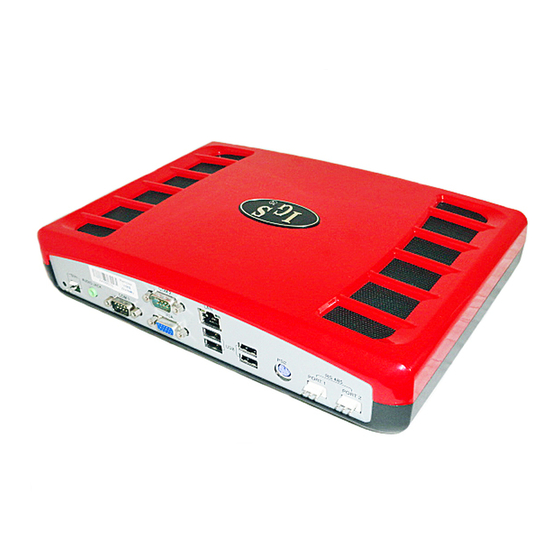
1. Product Overview 1.1 Packed Items 1.1.1 Control Box Item Appearance Control Box PW01 Power Supply PW02 2P Power Cable (1M) PW03 AC Power Cable (0.3M) CO1 Signal Cord (0.9M) CO2 Signal Cord (1.5M) Note: Two are spare parts (for extension use) CO4 Network Cable (2M) Note: For PC connection to access... -
Page 7: Display
CO7 Audio Cable (3M) Power Adapter Power cord Note: The display is provided as a kit, which includes the accessories listed above. If the display is not purchased from IGS, none of the accessories will be provided. 1. Product Overview... -
Page 8: Pc Board
1.1.3 PC Board Item Appearance PC Board CO3 Signal Cord (0.9M) CO2 Signal Cord (1.5M) Note: If 1 set of PC board (10 PCBs) is purchased, extra two CO2 signal cords will be provided as spare parts. 1. Product Overview... -
Page 9: Control Box
1.2 Control Box 1.2.1 Rear Panel Connector Connect to… Cable to be used Power supply PW02 2P Power Cable AUDIO JACK Display’s audio connector CO7 Audio Cable COM1 Reserved COM2 Reserved Display’s audio connector CO5 VGA Cable PC’s LAN port CO4 Network Cable USB X4 Reserved... -
Page 10: Pc Board
1.3 PC Board Connector Connect to… Cables to be used A RS-232 Bill Acceptor RS-232 cable (not provided) B RS-232 Second screen PC board C RS-232 Touch Panel +5V OUTPUT +5V Power LINK Control Box’s RS 485 Port 2 CO3 Signal Cord Connector Connect to…... -
Page 11: Installation - Linking System
2. Installation – Linking System The following diagram illustrates the connection of the whole system. Power Supply Control Box Display Lamp Audio PC Board (Slave Machines) Up to 24 slave machines can be connected Power adapter 2. Installation – Linking System... -
Page 12: Connecting Control Box To Power Supply
2.1 Connecting Control Box to Power Supply 1. PW02 2P Power Cable Connection 1a. Secure the wires to the screws terminals on the power supply. Make sure to follow the color coding as shown below. Black Cable → COM Yellow Cable → +V 1b. -
Page 13: Connecting Control Box To Pc Boards
2.2 Connecting Control Box to PC Boards Refer to the diagram above and use CO1, CO2 and CO3 signal cords to connect the control box to PC boards. Adjust DIP SW1 Settings for linking mode To use Linking Mode, all the PC boards’ DIP SW1 must be correctly adjusted: On all the PC boards, set No.8 of DIP SW1 to use Link Mode. -
Page 14: Connecting Control Box To Display
2.3 Connecting Control Box to Display Refer to the table below to connect the control box to the display. Type Cable to use Connect from… To… CO5 VGA cable, VGA jack on control box Display’s VGA connector Audio CO7 audio cable Audio Jack on control box Display’s audio connector. -
Page 15: Installation - Slave Machine
3. Installation – Slave Machine 3.1 Connection Diagram Reset 36- Pin Connector DIP SW2 DIP SW1 10-Pin Connector A RS-232 Connects to optional Citizen VGA port printer/ticket dispenser. Connects to screen * Use Belkin #F2L044 (serial printer cable/null modem) for Citizen printer. -
Page 16: Dip Switch Settings
4. DIP Switch Settings 4.1 Control Box DIP SW JACKPOT ONLY MUSIC JACKPOT VOLUME 100% TEST MODE 4. DIP Switch Settings... -
Page 17: Pc Board
4.2 PC Board DIP SW 1 SLAVE ID SINGLE LINK MODE LINK 4. DIP Switch Settings... - Page 18 DIP SW 2 TOUCH LINER Notes: To use linking mode, On each of the PC board, set No.8 of DIP SW1 to use Link Mode. On each of the PC board, set No.1~ 5 of DIP SW1 to use different slave ID. Note that ID #1 must be set first.
-
Page 19: Connection Diagram
5. Connection Diagram 5.1 Connection Diagram 36 Pins 10 Pins Parts Side Solder Side Parts Side Solder Side SPEAKER +12V +12V TICKET OUT TICKET SSR TICKET SWITCH START/ALL STOP STOP4/SMALL/HELP STOP5/PLAY STOP1/TAKE STOP3/DOUBLE/SELECT LINE 13 STOP2/HOLD PAIR/BIG COIN A KEY IN COIN C RECORD TEST... -
Page 20: Button Layout
5.2 Button Layout STOP 2 STOP 3 STOP 4 START STOP 1 STOP 5 W-UP SMALL ALL STOP TAKE PLAY HOLD PAIR SELECT LINE HELP TAKE 5. Connection Diagram... -
Page 21: Test
6. Test 6.1 PC Board Test To enter test mode: Press the [TEST] key and then power on the machine. Then you will enter the test mode and see the test menu. After you enter the test mode, you can conduct Key Test, Speech Test, RGB & CG Test, RS232 Test and so on. -
Page 22: Speech Test
6.1.2 Speech Test This page allows you to test the sounds and set up whether to loop the sound. 6.1.3 RGB & CG TEST Select this item to test RGB and CG . 6. Test... -
Page 23: Rs232 Test
6.1.4 RS232 Test This page allows you to test the RS-232 communication. If the communication functions normally, “OK” will be displayed. 6.1.5 Link Test For IGS test only. Please ignore this item. 6. Test... -
Page 24: Control Box Test
6.2 Control Box Test To enter Test Mode: 1. Adjust the Control Box’s DIP SW PIN 8 to the ON mode and then restart the machine. 2. After the machine is restarted, a message of “ENTER TEST MODE” will be displayed, meaning Test Mode is accessed. - Page 25 Item Description Troubleshooting local dealer. GRAPHIC Shows clear graphics or If there are white blocks or other unidentified TEST illustration, indicating the function illustrations, please check if the Video works. Memory Size in BIOS is set to 254M. (Refer to the instructions below.) If it is and the problems remain, then the board needs to be maintained.
-
Page 26: Settings Under Linking Mode
7. Settings under Linking Mode 7.1 Slave Machine Settings Under Linking Mode, you can adjust the slave machine settings on each slave machine. 1. At the machine for which you want to adjust settings, press [RECORD]. 2. Then press [SMALL]. 3. -
Page 27: Adjustment
7.1.1 Adjustment The [Adjustment] menu provides the options to set up the volume and bill acceptor settings. System PRINTER COMMAND allows customized setting for different brands of printer. Volume If connected with amplifier, please set the music volume from 12 to 13. 7. -
Page 28: Interface Setup
7.1.2 Interface Setup The [Interface Setup] menu provides the options to adjust touch screen rela ted settings. PRINTER Printer Setup allows you to list the necessary information such as address, message, and denomination on the print-out receipt. Touch If a touch screen is connected, you will need to enter this page to calibrate the screen. -
Page 29: Overall System Settings
Touch Reverse If a touch screen is connected, this page allows you to enable Horizontal Reverse and Vertical Reverse function as required. 7.2 Overall System Settings There are two methods to adjust the overall system settings: 1. From the PC board with Slave ID 1. 2. - Page 30 System Adjust The [System Adjust] page allows you to set up the system-related settings. The following table describes the items available in the [System Adjust] page. Item Content Setup selection Default Max. PLAY/LINE(25-liner) 2, 4, 8, 10, 15, 20, 30 Max.
- Page 31 Item Content Setup selection Default DOUBLE GAME NO, YES LEVEL 1 (easiest), LEVEL 2, LEVEL 3, LEVEL 4, MAIN GAME LEVEL LEVEL 6 LEVEL 5, LEVEL 6 (hardest) DOUBLE GAME LEVEL 95%, 90%, 85% Notes: 1. Jackpot range changes according to your JP MAX settings: Level 1 (Default) JACKPOT under Linking Mode Level 2...
- Page 32 Time This page allows you to set the date and time for whole linking system. Change Password This page allows you to change the password. After you confirm the password, wait for a moment until “CONFIRM OK” appears. Note: This password change only applies to the Slave 1 machine and is only valid for long-term data access.
-
Page 33: Setup Via Control Box
7.2.2 Setup via Control Box Under Link Mode, you can access the web-based setup system from the control box: The steps are as follows: 1. Using the CO4 cable, connect one end to the LAN port on the control box and the other end to the LAN port on the computer. - Page 34 System Reset Log on to the web-based setup system as described above. Expand the [System] menu and then click [System Reset] to reset the system. Time Adjust Log on to the web-based setup system as described above. Expand the [System] menu and then click [Time Adjust] to adjust time and date.
- Page 35 Changing Password Log on to the web-based setup system as described above. Expand the [System] menu and then click [Change Password] to change the password. 7. Settings under Linking Mode...
-
Page 36: Keyin/Out Via Control Box
7.3 KeyIn/Out via Control Box To key in/out credits, aside from using the keyin/keyout buttons on individual machine, you can also use the web-based management system on the control box. Log on to the control box’s web-based management system as described above. Expand the [Counter Control] menu and then click [Key in/out status]. - Page 37 (b) Its previous web-activated keyout process (if any) has been finished. (c) The machine is not in any error status. The key out steps: 1. Just click the Keyout button in the row of the slave machine you want to key out credits. Note that you cannot key out credits smaller than the Key Out Rate (set in System Adjust page).
-
Page 38: Bookkeeping
8. Bookkeeping Under the linking mode, you can access the bookkeeping data either from the PC board or from the control box. 8.1 Overall System Short/Long Term Data From 1 Slave Machine To access the bookkeeping data: 1. At the machine with slave ID1, press [RECORD] and then enter the password. 2. - Page 39 4. Click [Short Term] or [Long Term] according to the data you want to view. Short Term Data On the [Short Term] page, you can view each slave machine’s short-term data, including current and last data. To move the current data to the last data, click [UPDATE]. When prompted, click [Yes]. 8.
- Page 40 Long Term Data To access the long-term data, you need to enter the password to login. (Default password: igs_2008.) After login, select [Long Term] from the menu and you can view the long-term data. 8. Bookkeeping...
-
Page 41: Slave Machine Long/Short Term Data
8.2 Slave Machine Long/Short Term Data At any of the slave machine, press [RECORD] and then press [SMALL]. You can get long term data for main game and double-up game of that machine. The default password is pressing [START] for 8 times. Press [RECORD] [BIG]... -
Page 42: Reset Slave Machine Bookkeeping Via Control Box
8.3 Reset Slave Machine Bookkeeping via Control Box To reset a slave machine’s bookkeeping data, aside from using the reset toggle on individual machine, you can also use the web-based management system on the control box. 1. Lon to the control box’s web-based management system as described above. Expand the [Counter Control] menu and then click [Reset status]. -
Page 43: Selectable Games
9. Selectable Games Each selectable sub-title is presented as 15-reel & 9/25 liner styles with 3 bonus games. 9.1 Captain Jack Main Game 3 sets of Jackpots 9/25-liner adjustable Symbol zone Jackpot under Linking Mode Play the value of MIN. PLAY FOR JP (or above). Jackpot 1 Three-in-line (or above) wins 100% Jackpot 1. - Page 44 Free Game With next to each other left to right, the player wins a Free Game. Bonus Game 1 – City Map Bonus Game 2 – Trading with the Natives 9. Selectable Games...
- Page 45 Bonus Game 3 – Late Night Kisses Double Game Last 5 hands 9. Selectable Games...
-
Page 46: Midnight Castle
9.2 Midnight Castle Main Game Midnight Castle is a 15-reel & 9/25-liner game with 3 different bonus games. 3 sets of Jackpots 9 / 25-liner adjustable Symbol Zone Player may change the scene between day and night by pressing the 9. - Page 47 Feature During the game, will randomly hit the symbols on the wheel to make it spin again. 9. Selectable Games...
- Page 48 Jackpot under Linking Mode Play the value of MIN. PLAY FOR JP (or above). Jackpot 1 5-in-line wins 100% Jackpot 1. Jackpot 2 4-in-line wins 100% Jackpot 2. Jackpot 3 3-in-line wins 100% Jackpot 3. Free Game With next to each other from left to right, player enters the Free Game.
- Page 49 Bonus Game With 3X ( )symbols or more on the screen, the player enters the Bonus Game. Bonus Game1 Choose chamber from one to five to win a prize. Player wins extra credits according to the chosen symbol.. Game ends when chosen.
- Page 50 Bonus Game 3 Player enters the Liquor Wheel Game at first. Winning depends on the symbol chosen by player. When was chosen, player enters the Romantic Game. Game ends when was chosen. Double Game After winning the Main game or Bonus game, player can press [DOUBLE UP] [DOUBLE UP] button to play...
-
Page 51: Magic Show
9.3 Magic Show Main Game Magic Show is a 15-reel & 9/25-liner game with 3 different bonus games. 3 sets of Jackpots Symbol zone Auto play Jackpot under Linking Mode Play the value of MIN. PLAY FOR JP (or above). Jackpot 1 Three-in-line (or above) wins 100% Jackpot 1. - Page 52 Free Game With next to each other left to right, the play wins a Free Game. Bonus Game 1 – Balloon Magic Show 9. Selectable Games...
- Page 53 Bonus Game 2 – Teleportation Magic Show Bonus Game 3 – Sword Piercing Magic Show Double Game 9. Selectable Games...
-
Page 54: Chef Express
9.4 Chef Express Main Game Chef Express is a 15-reel & 9/25-liner game with 3 different bonus games. 3 sets of Jackpots 9 / 25-liner adjustable Symbol Zone Jackpot under Linking Mode Play the value of MIN. PLAY FOR JP (or above). JACKPOT 1 Three-in-line (or above) wins 100% Jackpot 1. - Page 55 Free Game With next to each other left to right, the player wins a Free Game. Bonus Game With 3X symbols or more on the screen, the player enters the Bonus Game. Bonus Game1 A Player moves according to the number rolled out from the reel.
- Page 56 Bonus Game 2 Select one of the windows to proceed the game. When was chosen, a player can pick a gift for her to win a higher bonus. The Bonus Game ends when the gift is presented to Bonus Game 3 Choose the meal by stopping the wheel in the middle.
-
Page 57: Getaway
9.5 Getaway Main Game Getaway is a 15-reel & 9/25-liner game with bonus games. 3 sets of Jackpots 9 / 25-liner adjustable Symbol Zone , , stand for all the other symbols on the screen except Jackpot under Linking Mode Play the value of MIN. - Page 58 Free Game When appear next to each other, player wins a FREE GAME. Bonus Game Collect 3, 4 or 5 initiates the BONUS GAME. Player gets extra credits by finding out $ symbol from the floor. Open the vault to get higher bonus.
- Page 59 Double Game Choose RED or BLACK to play a DOUBLE GAME. The winnings will be doubled when choosing the right color. 9. Selectable Games...
-
Page 60: Troubleshooting
10. Troubleshooting 10.1 Error messages and solutions Error Message Procedures Coin Error Power off the machine, check the coin counter and restart the machine. Credit Error Power off the machine and do System Reset by using the toggle switch. Win Error Power off the machine and do System Reset by using the toggle switch. -
Page 61: Solving Hopper Ssr Error
10.2 Solving Hopper SSR Error Error: After powering on the machine, the hopper keeps working and can’t be stopped. Cause: The Hopper SSR’s jump setting is incorrect. How to solve: 1. Locate the Hopper SSR jump (JP7) on the PC board. Then identify current HOPPER SSR is at HIGH ACTIVE or LOW ACTIVE. -
Page 62: Appendix A Network Settings
Appendix A Network Settings To access the control box’s Web-based setup system, your computer must be in the same subnet as the control box. To this end you should correctly configure the computer’s network settings. The following is using Windows 2000 as example. 1. - Page 63 M100US...
Need help?
Do you have a question about the Diamond Progressive and is the answer not in the manual?
Questions and answers