Table of Contents
Advertisement
Quick Links
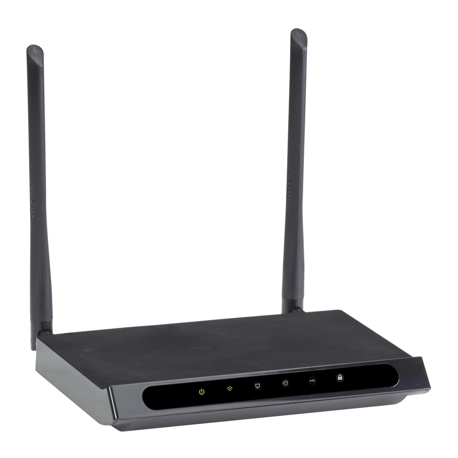
802.11ac WiFi Dual-Band Router
User Manual
Integrates a 4-port switch, firewall, NAT router, and wireless AP in one box.
Order toll-free in the U.S. or for FREE technical support: Call 877-877-BBOX
Contact
(outside U.S. call 724-746-5500)
Information
www.blackbox.com • info@blackbox.com
WRT750A
WRT750AE-PS
Advertisement
Table of Contents

Related Manuals for Black Box WRT750A


Summary of Contents for Black Box WRT750A
- Page 1 WRT750A WRT750AE-PS 802.11ac WiFi Dual-Band Router User Manual Integrates a 4-port switch, firewall, NAT router, and wireless AP in one box. Order toll-free in the U.S. or for FREE technical support: Call 877-877-BBOX Contact (outside U.S. call 724-746-5500) Information www.blackbox.com • info@blackbox.com...
- Page 2 Trademarks Used in this Manual Trademarks Used in this Manual Black Box and the Double Diamond logo are registered trademarks of BB Technologies, Inc. Any other trademarks mentioned in this manual are acknowledged to be the property of the trademark owners.
-
Page 3: Ce Mark Warning
Disclaimer: Black Box Network Services shall not be liable for damages of any kind, including, but not limited to, punitive, consequential or cost of cover damages, resulting from any errors in the product information or specifications set forth in this document and Black Box Network Services may revise this document at any time without notice. - Page 4 NOM Statement Instrucciones de Seguridad (Normas Oficiales Mexicanas Electrical Safety Statement) 1. Todas las instrucciones de seguridad y operación deberán ser leídas antes de que el aparato eléctrico sea operado. 2. Las instrucciones de seguridad y operación deberán ser guardadas para referencia futura. 3.
- Page 5 National Restrictions National Restrictions This device is intended for home and office use in all EU countries (and other countries following the EU directive 1999/5/EC) without any limitation except for the countries mentioned below: Country Restriction Reason/Remark Bulgaria None General authorization required for outdoor use and public service.
-
Page 6: Table Of Contents
Table of Contents Table of Contents 1. Specifications ..................................8 2. Overview ..................................... 10 2.1 Introduction ................................. 10 2.2 Features ..................................10 2.3 What's Included ................................11 2.4 Hardware Description ..............................11 2.4.1 Front Panel ................................. 11 2.4.2 Back Panel ................................13 3. - Page 7 Table of Contents 5.10.3 Storage Sharing ...............................66 5.10.4 FTP Server ................................67 5.10.5 Media Server ..............................69 5.11 NAT ..................................... 71 5.12 Forwarding .................................. 71 5.12.1 Virtual Servers ..............................71 5.12.2 Port Triggering ..............................73 5.12.3 DMZ ................................74 5.12.4 UPnP ................................75 5.13 Security ..................................76 5.13.1 Basic Security ..............................
-
Page 8: Specifications
Chapter 1: Specifications 1. Specifications Approvals Environmental Compliances RoHS2 EMI Certifications Safety Certifications Environmental Operating Humidity 5 to 90%, noncondensing Operating Temperature 32 to +104° F (0 to 40° C) Storage Humidity 5 to 90%, noncondensing Storage Temperature -40 to +70° F (-40 to +70° C) Management Diagnostics Power, Wireless, Ethernet, Internet, USB, WPS... - Page 9 Chapter 1: Specifications Physical (continued) Wireless Antennas (2) 2.4–2.5 GHz (2 dBi), 4.9–5.825 GHz detachable omnidirectional Wireless Frequencies 2.4–2.4835 GHz, 5.180–5.240 GHz, 5.745–5.825 GHz; NOTE: Only 2.412 to 2.462 GHz is allowed to be used in USA, which means only channels 1–11 are available for American users to choose.
-
Page 10: Overview
Chapter 1: Specifications 2. Overview 2.1 Introduction The Gigabit Dual Band Router - 802.11ac Wi-Fi integrates a 4-port Switch, Firewall, NAT-router and Wireless AP. The router delivers exceptional range and speed that fully meets the need of Small Office/Home Office (SOHO) networks and the users who demand higher networking performance. -
Page 11: What's Included
3. Click on the “Support” tab on the product page, and select the document you wish to download. If you have any trouble accessing the Black Box site to download the manual, you can contact our Technical Support at 877-877-2269 or info@blackbox.com. - Page 12 Chapter 2: Overview Table 2-1. Front-panel components. Number in Component Status Description Figure 2-1 Power LED Power is off. Power is on. Wireless LED The wireless function is disabled. The wireless function is enabled. The router is working on 2.4 GHz or 5 GHz or both radio bands.
-
Page 13: Back Panel
Chapter 2: Overview 2.4.2 Back Panel Figure 2-2 shows the back panel of the router. Table 2-2 describes its components. Figure 2-2. Router's back panel. The following parts are located on the back panel (View from left to right). Table 2-2. Back-panel components. Number in Component Description... - Page 14 Chapter 2: Overview Table 2-2 (continued). Back-panel components. Number in Component Description Figure 2-2 ON/OFF switch Powers the switch ON or OFF. Barrel connector for Connect the power adapter here. Use the power adapter provided with this router. Power (2) Wireless antennas Receive and transmit the wireless data.
-
Page 15: Installing The Router
Chapter 2: Overview 3. Installing the Router 3.1 System Requirements • Broadband Internet Access Service (DSL/Cable/Ethernet) • One DSL/Cable Modem that has an RJ-45 connector (not necessary if the router is connected directly to the Ethernet). • PCs with a working Ethernet Adapter and an Ethernet cable with RJ-45 connectors. •... - Page 16 Chapter 3: Installing the Router Figure 3-1. Hardware installation. Figure 3-2. USB installation. NOTE: If you want to use the router to share files, plug the USB storage device into the USB port. 877-877-2269 | blackbox.com Page 16...
-
Page 17: Quick Installation Guide
Chapter 3: Installing the Router 4. Quick Installation Guide This chapter will show you how to configure the basic functions of your Gigabit Dual Band Router - 802.11ac Wi-Fi using the Quick Setup Wizard within minutes. 4.1 TCP/IP Configuration The default IP address of the router is 192.168.1.1 and the default Subnet Mask is 255.255.255.0. These values can be changed as you desire. -
Page 18: Quick Installation Steps
Chapter 4: Quick Installation Guide To check the connection, follow these steps: 1. Is the connection between your PC and the router correct? NOTE: The Ethernet LED on the router and LEDs on your PC‘s adapter should be lit. 2. Is the TCP/IP configuration for your PC correct? NOTE: If the router‘s IP address is 192.168.1.1, your PC’s IP address must be within the range of 192.168.1.2–192.168.1.254. - Page 19 Chapter 4: Quick Installation Guide 2. After successful login, the Quick Setup page will appear for you to quickly configure your router. Figure 4-5. Quick setup screen. 3. Click Next, and then WAN Connection Type page will appear. Figure 4-6. WAN Connection Type. The router provides an Auto-Detect function and supports five types of WAN connection: Dynamic IP, Static IP, PPPoE/Russian PPPoE, L2TP/Russian L2TP, and PPTP/Russian PPTP.
- Page 20 Chapter 4: Quick Installation Guide 1. If the connection type detected is Dynamic IP, the MAC Clone page will appear. In most cases, you don’t need to clone the MAC address. Select “No, I do NOT need to clone MAC address” and then click “Next.” If you need to clone the file, select “Yes, I need to clone MAC address”...
- Page 21 Chapter 4: Quick Installation Guide • Gateway—Your ISP will provide the Gateway address which is the ISP server’s address. Enter the gateway IP address into the box if required. • DNS Server (Optional)―Enter the DNS Server IP address into the box if required. •...
- Page 22 Chapter 4: Quick Installation Guide Figure 4-10. Quick Setup—L2TP/Russia L2TP. • Username/Password—Enter the Username and Password provided by your ISP. These fields are case-sensitive. If you have difficulty with this process, contact your ISP. Select Static IP if the IP Address/ Subnet Mask/ Gateway and DNS server address have been provided by your ISP. Then please enter server IP address or domain name provided by your ISP, and also enter the corresponding parameters.
- Page 23 Chapter 4: Quick Installation Guide Figure 4-12. Dynamic IP screen. 5. If your connection type is PPTP/Russia PPTP, select PPTP/Russia PPTP in Figure 4-6 and the next screen will appear as shown in Figure 4-13. Configure the following parameters and then click “Next” to continue. Figure 4-13.
- Page 24 Chapter 4: Quick Installation Guide Figure 4-14. Static IP screen. Select Dynamic IP if none of the above parameters are provided. Then you just need to enter server IP address or domain name provided by your ISP. Figure 4-15. Dynamic IP screen. 6.
- Page 25 Chapter 4: Quick Installation Guide 7. Configure the basic parameters for 2.4 GHz wireless network in the following screen as shown in Figure 3 13, and then click Next. Figure 4-17. Quick Setup—Wireless 2.4 GHz. • Wireless Network Name—Also called the SSID (Service Set Identification). Enter a value of up to 32 characters. The same name must be assigned to all wireless devices in your network.
- Page 26 Chapter 4: Quick Installation Guide Figure 4-18. More Advanced Wireless Settings screen. • Band - This field displayed the operating frequency being configured. • Mode - This field determines the wireless mode which the router works on. - 11bg mixed —Select if you are using both 802.11b and 802.11g wireless clients. - 11bgn mixed—Select if you are using a mix of 802.11b, 11g, and 11n wireless clients.
- Page 27 Chapter 4: Quick Installation Guide • Region—Select your region from the drop-down list. This field specifies the region where the wireless function of the router can be used. It may be illegal to use the wireless function of the router in a region other than one of those specified in this field. If your country or region is not listed, contact your local government agency for assistance.
- Page 28 Chapter 4: Quick Installation Guide Figure 4-21. Quick Setup—Confirm. 10. Click the Finish button to complete the Quick Setup. Figure 4-22. Quick Setup—Finish. 877-877-2269 | blackbox.com Page 28...
-
Page 29: Configuring The Router
Chapter 4: Quick Installation Guide Chapter 5. Configuring the Router This chapter will show each key function of the Web page and its configuration method. To access the configuration utility, open a web-browser and type in the default address http://192.168.1.1 in the address field of the browser. -
Page 30: Status
Chapter 5: Configuring the Router 5.2 Status The Status page provides the current status information about the router. All information is read-only. Figure 5-2. Status screen. 877-877-2269 | blackbox.com Page 30... -
Page 31: Quick Setup
Chapter 5: Configuring the Router 5.3 Quick Setup Please refer to Section 4.2, Quick Installation Steps. 5.4 Network Figure 5-3. Network menu. There are three submenus under the Network menu (shown in Figure 5-2): WAN, LAN, and MAC Clone. Click any of them, and you will be able to configure the corresponding function. - Page 32 Chapter 5: Configuring the Router • E nable IGMP Proxy—IGMP (Internet Group Management Protocol) is used to manage multicasting on TCP/IP networks. Some ISPs use IGMP to perform remote configuration for client devices, such as the modem router. The default value is enabled, and if you are not sure, please contact your ISP or just leave it.
- Page 33 Chapter 5: Configuring the Router 3. If your ISP provides a PPPoE connection, select the PPPoE/Russia PPPoE option. Enter the following parameters: Figure 5-6. WAN—PPPoE. • PPP Username/PPP Password —Enter the User Name and Password provided by your ISP. These fields are case-sensitive. •...
- Page 34 Chapter 5: Configuring the Router - Connect Manually—You can click the Connect/Disconnect button to connect/disconnect immediately. This mode also supports the Max Idle Time function as Connect on Demand mode. The Internet connection can be disconnected automatically after a specified inactivity period and re-established when you attempt to access the Internet again. Click the Connect button to connect immediately.
- Page 35 Chapter 5: Configuring the Router • Username/Password—Enter the User Name and Password provided by your ISP. These fields are case-sensitive. • Auth Server—Enter the authenticating server IP address or host name. • Auth Domain—Type in the domain suffix server name based on your location. For example: NSW / ACT - nsw.bigpond.net.au VIC / TAS / WA / SA / NT - vic.bigpond.net.au...
- Page 36 Chapter 5: Configuring the Router Figure 5-8. WAN—L2TP/Russia L2TP. • Username/Password—Enter the User Name and Password provided by your ISP. These fields are case-sensitive. • Addressing Type—Choose the addressing type given by your ISP, either Dynamic IP or Static IP. Click the Connect button to connect immediately.
- Page 37 Chapter 5: Configuring the Router CAUTION: Sometimes the connection cannot be disconnected even though you specify a Max Idle Time, because some applications are visiting the Internet continually in the background. Click the Save button to save your settings. 6. If your ISP provides PPTP connection, select the PPTP option. Enter the following parameters: Figure 5-9.
-
Page 38: Lan
Chapter 5: Configuring the Router - Connect on Demand—You can configure the router to disconnect from your Internet connection after a specified period of inactivity (Max Idle Time). If your Internet connection has been terminated due to inactivity, Connect on Demand enables the router to automatically re-establish your connection as soon as you attempt to access the Internet again. -
Page 39: Mac Clone
Chapter 5: Configuring the Router NOTES: 1. If you change the IP Address of LAN, you must use the new IP Address to log in the router. 2. If the new LAN IP Address you set is not in the same subnet, the IP Address pool of the DHCP server will change accordingly at the same timewhile the Virtual Server and DMZ Host will not take effect until they are re-configured. -
Page 40: Wireless 2.4 Ghz
Chapter 5: Configuring the Router 5.6 Wireless 2.4 GHz Figure 5-13. Wireless menu. There are six submenus under the Wireless menu: Basic Settings, WPS, Wireless Security, Wireless MAC Filtering, Wireless Advanced, and Wireless Statistics. Click any of them, and you will be able to configure the corresponding functions. 5.6.1 Basic Settings Choose menu “Wireless 2.4GHz ―... - Page 41 Chapter 5: Configuring the Router Figure 5-15. Message from webpage dialog box. NOTE: Limited by local law regulations, version for North America does not have region selection option. • Mode—Select the desired mode. - 11bg mixed—Select if you are using both 802.11b and 802.11g wireless clients. - 11bgn mixed—Select if you are using a mix of 802.11b, 11g, and 11n wireless clients.
-
Page 42: Wps
Chapter 5: Configuring the Router • Scan—Click this button, you can search the AP which runs in the current channel. • Key type—This option should be chosen according to the AP's security configuration. We recommend setting the security type the same as your AP's security type. •... - Page 43 Chapter 5: Configuring the Router Figure 5-18. WPS/Reset button on the back of the router. Figure 5-19. Add A New Device. Step 2: Press and hold the WPS button of the client device. Step 3: The Wi-Fi Protected Setup LED flashes for two minutes during the Wi-Fi Protected Setup process. Step 4: When the WPS LED is on, the client device has successfully connected to the router.
-
Page 44: Wireless Security
Chapter 5: Configuring the Router Step 2: The Wi-Fi Protected Setup LED flashes for two minutes during the Wi-Fi Protected Setup process. Step 3: When the WPS LED is on, the client device has successfully connected to the router. NOTES: 1. - Page 45 Chapter 5: Configuring the Router NOTE: If you check the WPA/WPA2-Personal radio button and choose TKIP encryption, you will find a notice in red as shown in Figure 5-22. Figure 5-22. WPA/WPA2—Personal. - Wireless Password—You can enter between 8 and 63 ASCII characters or 8 and 64 hexadecimal characters. The default password is the same as the default PIN code, which is labeled on the bottom of the router.
-
Page 46: Wireless Mac Filtering
Chapter 5: Configuring the Router Figure 5-24. WEP. - Authentication Type—you can choose the type for the WEP security on the drop-down list. The default setting is Auto, which can select Shared Key or Open System authentication type automatically based on the wireless station‘s capability and request. - WEP Key Format—Hexadecimal and ASCII formats are provided here. - Page 47 Chapter 5: Configuring the Router To filter wireless users by MAC Address, click Enable. The default setting is Disabled. • MAC Address—The wireless station's MAC address that you want to filter. • Status—The status of this entry, either Enabled or Disabled. •...
-
Page 48: Wireless Advanced
Chapter 5: Configuring the Router 4b. Enter wireless station A/B in the Description field. 4c. Select Enabled in the Status drop-down list. 4d. Click the Save button. The filtering rules that you configured should be similar to the following list: Figure 5-27. -
Page 49: Wireless Statistics
Chapter 5: Configuring the Router • DTIM Interval—This value determines the interval of the Delivery Traffic Indication Message (DTIM). A DTIM field is a countdown field informing clients of the next window for listening to broadcast and multicast messages. When the router has buffered broadcast or multicast messages for associated clients, it sends the next DTIM with a DTIM Interval value. -
Page 50: Wireless 5 Ghz
Chapter 5: Configuring the Router 5.7 Wireless 5 GHz Figure 5-30. Wireless menu. There are six submenus under the Wireless menu: Basic Settings, WPS, Wireless Security, Wireless MAC Filtering, Wireless Advanced, and Wireless Statistics. Click any of them, and you will be able to configure the corresponding functions. 5.7.1 Basic Settings Choose “Wireless 5GHz —>... - Page 51 Chapter 5: Configuring the Router Figure 5-32. Message from webpage dialog box. NOTE: Limited by local law regulations, the version for North America does not have region selection option. • Mode—Select the desired mode. - 11an mixed—Select if you are using both 802.11a and 802.11n wireless clients. If you set the Mode 11an mixed, all of 802.11a and 802.11n wireless stations can connect to the router.
-
Page 52: Wps
Chapter 5: Configuring the Router • Key type—Choose this option according to the AP's security configuration. We recommend that you set the security type the same as your AP's security type. • WEP Index—Choose this option if the key type is WEP(ASCII) or WEP(HEX). It indicates the index of the WEP key. •... - Page 53 Chapter 5: Configuring the Router Figure 5-35. Back panel of the router. Figure 5-36. Add A New Device. Step 2: Press and hold the WPS button of the client device. Step 3: The Wi-Fi Protected Setup LED flashes for two minutes during the Wi-Fi Protected Setup process. Step 4: When the WPS LED is on, the client device has successfully connected to the router.
-
Page 54: Wireless Security
Chapter 5: Configuring the Router Step 1: On the client device, enter the PIN number listed on the router’s Wi-Fi Protected Setup screen. (It is also labeled on the bottom of the router.) Step 2: The Wi-Fi Protected Setup LED flashes for two minutes during the Wi-Fi Protected Setup process. Step 3: When the WPS LED is on, the client device has successfully connected to the router. - Page 55 Chapter 5: Configuring the Router - Encryption—When WPA-PSK or WPA is set as the Authentication Type, you can select either Automatic, or TKIP or AES as Encryption. NOTE: If you check the WPA/WPA2-Personal radio button and choose TKIP encryption, you will find a notice in red. Figure 5-39.
-
Page 56: Wireless Mac Filtering
Chapter 5: Configuring the Router Figure 5-41. WEP. - Authentication Type—You can choose the type for the WEP security on the drop-down list. The default setting is Automatic, which selects Shared Key or Open System authentication type automatically based on the wireless station's capability and request. - Page 57 Chapter 5: Configuring the Router • MAC Address—The wireless station's MAC address that you want to filter. • Status—The status of this entry, either Enabled or Disabled. • Host-—The host network for the filtering rules. • Description—A simple description of the wireless station. To Add a Wireless MAC Address filtering entry, click the Add New button.
-
Page 58: Wireless Advanced
Chapter 5: Configuring the Router 3. Delete all or disable all entries if there are any entries already. 4. Click the Add New button. 5. Enter the MAC address 00:0A:EB:B0:00:0B /00:0A:EB:00:07:5F in the MAC Address field. 6. Enter wireless station A/B in the Description field. 7. -
Page 59: Wireless Statistics
Chapter 5: Configuring the Router • RTS Threshold—Here you can specify the RTS (Request to Send) Threshold. If the packet is larger than the specified RTS Threshold size, the router will send RTS frames to a particular receiving station and negotiate the sending of a data frame. The default value is 2346. -
Page 60: Guest Network
Chapter 5: Configuring the Router 5.8 Guest Network Choose “Guest Network,” then you can configure the Guest Network Wireless Settings on the page. Figure 5-47. Guest Network Wireless Settings. 877-877-2269 | blackbox.com Page 60... -
Page 61: Dhcp
Chapter 5: Configuring the Router • Allow Guest To Access My Local Network—If enabled, guests can communicate with hosts. • Allow Guest To Access My USB Storage Sharing—If enabled, guests can access to USB storage sharing servers. • Guest Network Isolation— If enabled, guests are isolated from each other. •... -
Page 62: Dhcp Clients List
Chapter 5: Configuring the Router • DHCP Server—Enable or Disable the DHCP server. If you disable the Server, you must have another DHCP server within your network; otherwise, you must configure the computer manually. • Start IP Address—Specify an IP address for the DHCP Server to start with when assigning IP addresses. 192.168.1.100 is the default start address. - Page 63 Chapter 5: Configuring the Router Figure 5-51. Address Reservation. • MAC Address—The MAC address of the PC for which you want to reserve an IP address. • IP Address—The IP address reserved for the PC by the router. • Status—The status of this entry, either Enabled or Disabled. To reserve an IP address: 1.
-
Page 64: Usb Settings
Chapter 5: Configuring the Router 5.10 USB Settings Figure 5-53. The USB Settings menu. There are six submenus under the USB Settings menu: USB Mass Storage, User Accounts, Storage Sharing, FTP Server, and Media Server. Click any of them, and you will be able to configure the corresponding functions. 5.10.1 USB Mass Storage The USB Mass Storage page provides basic information about the USB mass storage device. - Page 65 Chapter 5: Configuring the Router Figure 5-55. User Account Management screen. Only an Administrator can use a Web browser to transfer the files from a PC to the writable shared volume on the USB drive. To add a new user account, follow the steps below: 1.
-
Page 66: Storage Sharing
Chapter 5: Configuring the Router 5.10.3 Storage Sharing Choose “USB Settings―Storage Sharing,” then you can configure a USB disk drive attached to the router and view volume and share properties such as share name, directory, user access, and status on this page as shown below. Figure 5-56. -
Page 67: Ftp Server
Chapter 5: Configuring the Router Figure 5-57. Add or Modify Share Folder screen. 2. Enter the display name of the shared folder in Shared Name field. 3. Click the Browse button to select the folder that you want to share. 4. - Page 68 Chapter 5: Configuring the Router Figure 5-58. FTP Server Configuration. • Server Status—Indicates the FTP Server's current status. • Internet Access—Select enable to allow access of the FTP server from the Internet. Otherwise, select disable to only allow local network access. •...
-
Page 69: Media Server
Chapter 5: Configuring the Router Figure 5-59. Add or Modify Share Folder. 2. Enter display name of the share folder in Shared Name field. 3. Click the Browse button to select the folder that you want to share. 4. Click the Apply button to save the settings. NOTES: 1. - Page 70 Chapter 5: Configuring the Router • Server Name—The name of this Media Server. • Share Name—The display name of this folder. • Folder Name—The real full path of the specified folder. • Delete—You can delete the share folder by clicking Delete. To set up your media server, follow the instructions below: 1.
-
Page 71: Nat
Chapter 5: Configuring the Router 3. Click the Scan Now button to scan all the share folders immediately. You can also select the Auto-scan, and at the same time, select an auto scan interval time from the drop-down list. In this case, the media server will auto scan the share folders. NOTE: The max share folders number is 6. - Page 72 Chapter 5: Configuring the Router Figure 5-65. Virtual Servers. • Service Port—The number of External Service Ports. You can enter a service port or a range of service ports (the format is XXX – YYY; XXX is the Start port and YYY is the End port). •...
-
Page 73: Port Triggering
Chapter 5: Configuring the Router To modify or delete an existing entry: 1. Find the desired entry in the table. 2. Click Edit or Delete as desired on the Edit column. Click the Enable/Disable Selected button to make selected entries enabled/disabled. Click the Delete Selected button to delete selected entries. -
Page 74: Dmz
Chapter 5: Configuring the Router Figure 5-68. Add or Modify a Triggering Entry. To modify or delete an existing entry: 1. Find the desired entry in the table. 2. Click Edit or Delete as desired in the Edit column. Click the Enable Selected button to enable selected entries. Click the Disable Selected button to disable selected entries. -
Page 75: Upnp
Chapter 5: Configuring the Router Figure 5-69. DMZ. To assign a computer or server to be a DMZ server: 1. Click the Enable button. 2. Enter the IP address of a local PC that is set to be DMZ host in the DMZ Host IP Address field. 3. -
Page 76: Security
Chapter 5: Configuring the Router 5.13 Security Figure 5-71. The Security menu. There are four submenus under the Security menu: Basic Security, Advanced Security, Local Management and Remote Management. Click any of them, and you will be able to configure the corresponding functions. 5.13.1 Basic Security Choose “Security ―... -
Page 77: Advanced Security
Chapter 5: Configuring the Router - IPSec Passthrough—Internet Protocol security (IPSec) is a suite of protocols for ensuring private, secure communications over Internet Protocol (IP) networks, through the use of cryptographic security services. To allow IPSec tunnels to pass through the router, click Enable. -
Page 78: Local Management
Chapter 5: Configuring the Router • TCP-SYN-FLOOD Packets Threshold (5–3600)—The default value is 50. Enter a value between 5–3600. When the current TCP- SYN-FLOOD Packets numbers is beyond the set value, the router will start up the blocking function immediately. •... -
Page 79: Parent Control
Chapter 5: Configuring the Router Figure 5-75. Remote Management. • Web Management Port—Web browser access normally uses the standard HTTP service port 80. This router's default remote management web port number is 80. For greater security, you can change the remote management web port to a custom port by entering that number in the box provided. - Page 80 Chapter 5: Configuring the Router Figure 5-76. Parent Control Settings. • Parent Control—Check Enable if you want this function to take effect; otherwise, check Disable. • MAC Address of the Parental PC—In this field, enter the MAC address of the controlling PC, or you can use the Copy To Above button.
- Page 81 Chapter 5: Configuring the Router 4. Set the time period allowed for the PC controlled to access the Internet. For detailed information, go to “Access Control ― Schedule.” 5. Click the Save button. Click the Delete Selected button to delete the selected entries in the table. For example: If you want the child PC with MAC address 00:11:22:33:44:AA to access www.google.com on Saturday only while the parent PC with MAC address 00:11:22:33:44:BB is without any restriction, follow the settings below.
-
Page 82: Access Control
Chapter 5: Configuring the Router Figure 5-77. Parent Control Settings. 5.15 Access Control Figure 5-78. Access Control. There are four submenus under the Access Control menu: Rule, Host, Target, and Schedule. Click any of them, and you will be able to configure the corresponding function. 877-877-2269 | blackbox.com Page 82... -
Page 83: Rule
Chapter 5: Configuring the Router 5.15.1 Rule Choose “Access Control ― Rule,” then you can view and set Access Control rules in the screen. Figure 5-79. Access Control Rule Management. • Enable Internet Access Control—Select the check box to enable the Internet Access Control function, so the Default Filter Policy can take effect. - Page 84 Chapter 5: Configuring the Router 9. Click the Save button. Figure 5-80. Add Internet Access Control Entry. For example: To allow the host with MAC address 00 : 11 : 22 : 33 : 44 : AA to access www.google.com only from 18:00 to 20:00 on Saturday and Sunday, and forbid other hosts in the LAN to access the Internet, follow the settings below: 1.
-
Page 85: Host
Chapter 5: Configuring the Router 5.15.2 Host Choose “Access Control ― Host,” then you can view and set a Host list in the screen. The host list is necessary for the Access Control Rule. Figure 5-82. Host Settings. • Description—Displays the description of the host and this description is unique. •... -
Page 86: Target
Chapter 5: Configuring the Router Figure 5-84. Add or Modify a Host Entry. For example: To restrict the internet activities of host with MAC address 00:11:22:33:44:AA, follow the settings below: 1. Click the Add New button in the Host Settings page to enter the Add or Modify a Host Entry page. 2. - Page 87 Chapter 5: Configuring the Router Figure 5-87. Add or Modify an Access Target Entry. I) In the Description field, create a unique description for the target (e.g., Target_1). II) In the IP Address field, enter the IP address of the target. III) Specify the Target Port manually.
-
Page 88: Schedule
Chapter 5: Configuring the Router I) In the Description field, create a unique description for the target (e.g. Target_1). II) In the Add URL Address field, enter the domain name, either the full name or the keywords (for example, google) in the blank. Any domain name with keywords in it (www.google.com, www.google.cn) will be blocked or allowed. -
Page 89: Advanced Routing
Chapter 5: Configuring the Router Click the Delete Selected button to delete selected entries in the table. Figure 5-92. Advanced Schedule Settings. For example: If you desire to restrict the internet activities of host with MAC address 00:11:22:33:44:AA to access www.google. com only from 18:00 to 20:00 on Saturday and Sunday, follow the steps below: 1. -
Page 90: Static Route List
Chapter 5: Configuring the Router 5.16.1 Static Route List Choose “Advanced Routing —> Static Route List,” then you can configure the static route in the next screen. A static route is a pre-determined path that network information must travel to reach a specific host or network. Figure 5-94. -
Page 91: System Routing Table
Chapter 5: Configuring the Router 5.16.2 System Routing Table Choose “Advanced Routing —> System Routing Table,” then you can view the System Routing Table in the next screen. System routing table views all of the valid route entries in use. The Destination IP address, Subnet Mask, Gateway, and Interface will be displayed for each entry. -
Page 92: Ip & Mac Binding
Chapter 5: Configuring the Router Click Save to make the settings take effect. • Description—This is the information about the rules such as address range. • Priority—The priority of the rule, ranging from 1 to 8. 1 stands for the highest priority. •... -
Page 93: Binding Settings
Chapter 5: Configuring the Router 5.18.1 Binding Settings This page displays the IP & MAC Binding Setting table. Figure 5-100. Binding Setting. • MAC Address—The MAC address of the controlled computer in the LAN. • IP Address—The assigned IP address of the controlled computer in the LAN. •... -
Page 94: Arp List
Chapter 5: Configuring the Router 5.18.2 ARP List To manage the computer, you can observe the computers in the LAN by checking the relationship of MAC address and IP address on the ARP list, and you can also configure the items on the ARP list. This page displays the ARP List; it shows all the existing IP & MAC Binding entries. -
Page 95: No-Ip.com Ddns
Chapter 5: Configuring the Router 5.19.1 No-ip.com DDNS If the dynamic DNS Service Provider you select is www.no-ip.com, the page will appear as shown next. Figure 5-103. No-ip.com DDNS Settings. To set up for DDNS, follow these instructions: 1. Enter the Domain Name you received from dynamic DNS service provider. 2. -
Page 96: Comexe.cn Ddns
Chapter 5: Configuring the Router 5.19.2 Comexe.cn DDNS If the dynamic DNS Service Provider you select is www.comexe.cn, the next page will appear. Figure 5-104. Comexe.cn DDNS Settings. To set up for DDNS, follow these instructions: 1. Enter the Domain Name your dynamic DNS service provider gave you. 2. -
Page 97: Dyndns.com Ddns
Chapter 5: Configuring the Router 5.19.3 Dyndns.com DDNS If the dynamic DNS Service Provider you select is www.dyndns.com, the page will appear as shown next. Figure 5-105. Dyndns.org DDNS Settings. To set up for DDNS, follow these instructions: 1. Enter the Domain Name you received from the dynamic DNS service provider. 2. -
Page 98: Ipv6 Status
Chapter 5: Configuring the Router 5.20.1 IPv6 Status Figure 5-107. IPv6 Status. The IPv6 Status page displays the router's current IPv6 status and configuration. All information is read-only. • WAN - Connection Type—The IPv6 connection for the WAN. - Connection Status—The status of the IPv6 connection. - IPv6 Address—The WAN IPv6 address. -
Page 99: Ipv6 Wan
Chapter 5: Configuring the Router 5.20.2 IPv6 WAN Figure 5-108. Enable/Disable IPv6. • Connection Type - Choose the correct WAN connection type based on your ISP network topology. - Dynamic IPv6—Connections that use dynamic IPv6 address assignment. - Static IPv6—Connections that use static IPv6 address assignment. - PPPoEv6—Connections that use PPPoEV6 that requires a user name and password. - Page 100 Chapter 5: Configuring the Router • IPv6 Address—The IPv6 address assigned by your ISP dynamically. • Prefix Length—The length of IPv6 address prefix. • IPv6 Gateway—Enter the default gateway provided by your ISP. • Addressing Type—There are two types of assignments for the IPv6 address: SLAAC (Stateless address auto-configuration) and DHCPv6 (Dynamic Host Configuration Protocol for IPv6) Server.
- Page 101 Chapter 5: Configuring the Router • Enable MLD Proxy—Enable the Multicast Listener Discovery (MLD) Proxy function if you need it. 3. PPPoEv6 Figure 5-111. PPPoEv6. • PPP Username/Password—Enter the User Name and Password provided by your ISP. These fields are case-sensitive. •...
-
Page 102: Ipv6 Lan
Chapter 5: Configuring the Router This type is used when your WAN connection is IPv4 and the LAN connection is IPv6. • WAN Connection - Display the available wan connection. Click the Save button to save your settings. 5.20.3 IPv6 LAN Figure 5-113. -
Page 103: Time Settings
Chapter 5: Configuring the Router 5.21.1 Time Settings Choose “System Tools―Time Settings,” then you can configure the time on the following screen. Figure 5-115. Time settings. • Time Zone—Select your local time zone from this pull down list. • Date—Enter your local date in MM/DD/YY into the right blanks. •... -
Page 104: Diagnostics
Chapter 5: Configuring the Router To set Daylight Saving: 1. Check the box to enable Daylight Saving. 2. Select the start time from the drop-down lists in the Start field. 3. Select the end time from the drop-down lists in the End field. 4. -
Page 105: Firmware Upgrade
Chapter 5: Configuring the Router • Diagnostic Tool—Check the radio button to select one diagnostic tool. • Ping—This diagnostic tool troubleshoots connectivity, reachability, and name resolution to a given host or gateway. • Traceroute—This diagnostic tool tests the performance of a connection. NOTE: You can use ping/traceroute to test both numeric IP address and domain name. -
Page 106: Factory Defaults
Chapter 5: Configuring the Router • Firmware Version—Displays the current firmware version. • Hardware Version—Displays the current hardware version. The hardware version of the upgrade file must be higher than the router’s current hardware version. To upgrade the router's firmware, follow these instructions: 1. -
Page 107: Reboot
Chapter 5: Configuring the Router • Click the Backup button to save all configuration settings as a backup file in your local computer. • To upgrade the router's configuration, follow these instructions. - Click the Browse button to find the configuration file that you want to restore. - Click the Restore button to update the configuration with the file whose path is the one you input or selected in the blank. -
Page 108: System Log
Chapter 5: Configuring the Router NOTE: The new user name and password must not exceed 14 characters in length and not include any spaces. Enter the new Password twice to confirm it. Click the Save button when finished. Click the Clear All button to clear all. 5.21.8 System Log Choose “System Tools —>... - Page 109 Chapter 5: Configuring the Router • Statistics Status—Enable or Disable. The default value is disabled. To enable it, click the Enable button. If it is disabled, the function of DoS protection in Security settings will be disabled. • Statistics Interval (5-60)—The default value is 10. Select a value between 5 and 60 seconds in the drop-down list. The Packets Statistic interval indicates the time section of the packets statistic.
-
Page 110: Logout
Chapter 5: Configuring the Router 5.22 Logout Choose ”Logout,” and you will be back to the login screen as shown in Figure 5-125. Figure 5-126. Login screen. 877-877-2269 | blackbox.com Page 110... -
Page 111: Appendix A: Faq
Chapter 5: Configuring the Router Appendix A. FAQ 1. How do I configure the router to access the Internet via ADSL users? 1a. First, configure the ADSL Modem in the RFC1483 bridge model. 1b. Connect the Ethernet cable from your ADSL Modem to the WAN port on the router. The telephone cord plugs into the Line port of the ADSL Modem. - Page 112 Appendix A: FAQ Figure A-3. MAC Clone. 3. I want to use Netmeeting, what do I need to do? 3a. If you start Netmeeting as a host, you don’t need to do anything with the router. 3b. If you start as a response, you need to configure Virtual Server or DMZ Host and make sure the H323 ALG is enabled. 3c.
- Page 113 Appendix A: FAQ 4. How to enable DMZ Host: Log in to the router, click the “Forwarding” menu on the left of your browser, and click "DMZ" sub- menu. On the "DMZ" page, click Enable radio button and type your IP address into the “DMZ Host IP Address” field, using 192.168.1.169 as an example;...
- Page 114 Appendix A: FAQ 6c. Make sure the wireless stations have the correct KEY for encryption when the router is encrypted. 6d. If the wireless connection is ready, but you can’t access the router, check the IP Address of your wireless stations. 877-877-2269 | blackbox.com Page 114...
-
Page 115: Appendix B: Configuring The Pc
Appendix A: FAQ Appendix B: Configuring the PC In this section, we’ll introduce how to install and configure the TCP/IP correctly in Windows XP. First make sure your Ethernet Adapter is working, then refer to the adapter’s manual if needed. Follow these steps to install the TCP/IP component. - Page 116 Appendix B: Configuring the PC 5. The following TCP/IP Properties window will display and the IP Address tab is open on this window by default. 6. Select Obtain an IP address automatically and Obtain DNS server automatically, as shown in the next Figure. Figure B-3.
-
Page 117: Appendix C: Glossary
Appendix B: Configuring the PC Appendix C. Glossary 802.11ac - IEEE 802.11ac is a wireless computer networking standard of 802.11.This specification will enable multi-station WLAN throughput of at least 1 gigabit per second .This is accomplished by extending the air interface concepts embraced by 802.11n: wider RF bandwidth, more MIMO spatial streams, multi-user MIMO, and high-density modulation (up to 256 QAM). - Page 118 Appendix C: Glossary 877-877-2269 | blackbox.com Page 118...
- Page 119 NOTES 877-877-2269 | blackbox.com Page 119...
- Page 120 About Black Box Black Box provides an extensive range of networking and infrastructure products. You’ll find everything from cabinets and racks and power and surge protection products to media converters and Ethernet switches all supported by free, live 24/7 Tech support available in 60 seconds or less.
Need help?
Do you have a question about the WRT750A and is the answer not in the manual?
Questions and answers