Table of Contents
Advertisement
Advertisement
Table of Contents

Related Manuals for Black Box LGB2008A-R2


Summary of Contents for Black Box LGB2008A-R2
- Page 1 Copyright 200 . Black Box Corporation. All rights reserved. ©...
- Page 2 877-877-BBOX (outside U.S. call 724-746-5500 FREE technical support 24 hours a day, 7 days a week: Call 724-746-5500 or fax 724-746-0746 SUPPORT Mailing address: Black Box Corporation , 1000 Park Drive, Lawrence, PA 15055-1018 INFORMATION Web site: www.blackbox.com E-mail: info@blackbox.com...
- Page 3 FCC AND ICRFI STATEMENTS FEDERAL COMMUNICATIONS COMMISSION INDUSTRYCANADA RADIO FREQUENCY INTERFERENCE STATEMENTS This equipment generates, uses, and can radiate radio-frequency energy, and if not installed and used properly, that is, in strict accordance with the manufacturer’s instructions, may cause interference to radio communication.
- Page 4 8-Port 1000BASE-TX Web-Smart Ethernet Switch with 2 SFP Dual Media Ports INSTRUCCIONES DE SEGURIDAD (Normas Oficiales Mexicanas Electrical Safety Statement) 1. Todas las instrucciones de seguridad y operación deberán ser leídas antes de que el aparato eléctrico sea operado. 2. Las instrucciones de seguridad y operación deberán ser guardadas para referencia futura. 3.
- Page 5 Any other trademarks mentioned in this manual are acknowledged to be the property of the trademark owners. NOTE The 8-Port 1000BASE-TX Web-Smart Ethernet Switch with 2 SFP Dual Media Ports is called the Giga Switch in the software screens and also in the screens shown in this manual. Both names refer to the LGB2008A-R2 switch.
-
Page 6: Table Of Contents
8-Port 1000BASE-TX Web-Smart Ethernet Switch with 2 SFP Dual Media Ports Contents Chapter Page 1. Specifications ..............................6 2. Overview ................................7 2.1 Introduction ..............................7 2.2 What’s Included ............................7 2.3 Hardware Description ..........................8 2.3.1 Front Panel ............................8 2.3.2 Rear Panel ............................9 2.4 Optional SFP Fiber Transceiver Modules ....................9 3. -
Page 7: Chapter Page
4.3.2 Detailed Statistics ............................46 4.4 Maintenance ..............................49 4.4.1 Status ................................49 4.4.2 Warm Restart ...............................57 4.4.3 Factory Default ............................58 4.4.4 Logout ................................59 5. Troubleshooting ...............................60 5.1 Problems You May Experience ........................60 5.2 Calling Black Box ............................61 5.3 Shipping And Packaging ..........................61... -
Page 8: Specifications
8-Port 1000BASE-TX Web-Smart Ethernet Switch with 2 SFP Dual Media Ports 1. Specifications Standards: IEEE 802.3, 802.3ab, 802.3z, 802.3u, 802.3x port-based network access control, 802.1q tag-based VLAN Compatible Fiber Transceiver Modules: Ports 7 and 8 are TP/SFP fiber dual-media ports with auto detection function;... -
Page 9: Overview
Allow one or more links to be aggregated together to form a Link Aggregation Group by the static setting. 2.2 What’s Included Your package should include the following items. If anything is missing or damaged, contact Black Box at 724-746-5500. -
Page 10: Hardware Description
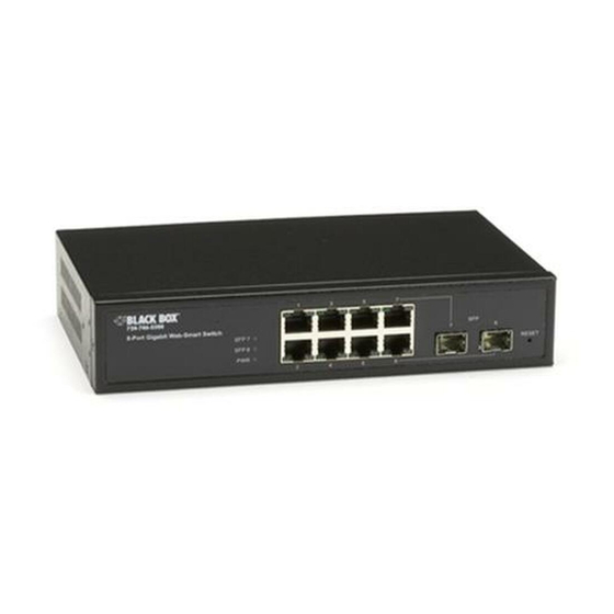
8-Port 1000BASE-TX Web-Smart Ethernet Switch with 2 SFP Dual Media Ports 2.3 Hardware Description 2.3.1 F RONT ANEL There are 8 TP Gigabit Ethernet ports and 2 SFP fiber ports for optional removable modules on the front panel of the switch. LED display area contains a Power LED, which indicates the power status and 8 ports working status of the switch. -
Page 11: Rear Panel
2.4 Optional SFP Fiber Transceiver Modules Ports 7–8 on the LGB2008A-R2 include two types of media: twisted-pair (TP) and optional small form factor pluggable (SFP) fiber (LC, BiDi LC, etc.) modules. The twisted-pair ports are the switch’s two rightmost RJ-45 twisted-pair connectors (ports 7–8). -
Page 12: Installation
2. Slide the module into the slot as shown in Figure 3-1. Make sure that the module is properly seated against the slot socket/connector. 8-Port 1000BASE-TX Web Smart Ethernet Switch (LGB2008A-R2) SFP Fiber Transceiver Module Figure 3-1. Installing an optional SFP fiber transceiver in the switch. -
Page 13: Connecting The Cable
3.1.2 C ONNECTING ABLE The switch’s twisted-pair ports support MDI/MDI-X auto-crossover, so you can use either straight-through or cross-pinned UTP cable. Use Category 5 or 5e grade RJ-45 twisted-pair cable to connect up to 24 network devices (such as workstations or servers) to the switch’s UTP ports. -
Page 14: Switch Cascading
3.2.3 S WITCH ASCADING Theoretically, the switch partitions the collision domain for each port in switch cascading so that you may up-link an unlimited number of switches. In practice, the network extension (cascading levels and overall diameter) must comply with the IEEE 802.3/802.3u/802.3z and other 802.1 series protocol specifications, which limit the timing requirement from physical signals defined by the Media Access Control (MAC) and PHY802.3 series specification, and timer from some OSI layer 2 protocols such as 802.1d, 802.1q, and LACP. - Page 15 Example 2: Port-based VLAN If VLAN is enabled and configured, each node in the network that can communicate with each other directly is in the same VLAN. The switch supports both port-based VLAN and tag-based VLAN. They are different in practical deployment, especially in physical location.
- Page 16 Example 3: Another Port-Based VLAN 8-Port 1000BASE-TX Web-Smart 8-Port 1000BASE-TX Web-Smart Ethernet Switch with 2 SFP Dual Ethernet Switch with 2 SFP Dual Media Ports Media Ports VLAN 1 VLAN 2 VLAN 3 VLAN 4 Figure 3-4. Two switches connected to two VLANs, each in a port-based VLAN. NOTES VLAN 1 members can’t access VLAN 2, VLAN 3, and VLAN 4 members.
-
Page 17: Configuring The Management Agent
Example 4. The same VLAN members can be at different switches with the same VID 8-Port 1000BASE-TX Web-Smart 8-Port 1000BASE-TX Web-Smart Ethernet Switch with 2 SFP Dual Media Ports Ethernet Switch with 2 SFP Dual Media Ports VLAN 1 VLAN 2 VLAN 3 Figure 3-5. -
Page 18: Typical Applications
3.5 Typical Applications Three sample setups are shown in Figures 3-6 through 3-8. In Figure 3-6, the switch is connected to Gigabit Ethernet devices or segments via auto MDI-X. It also uses the two fiber module slots for LC fiber connections. Figure 3-6. - Page 19 Figure 3-7 shows a peer-to-peer connection. 8-Port 1000BASE-TX Web-Smart Ethernet Switch with 2 SFP Dual Media Ports Financial Figure 3-7. Peer-to-peer network connection. 8-Port 1000BASE-TX Web-Smart Ethernet Switch with 2 SFP Dual Media Ports...
- Page 20 Figure 3-8 illustrates how the switch connects with other network devices and hosts. Sales R&D 8-Port 1000BASE-TX Web-Smart Ethernet Switch with 2 SFP Dual Media Ports Financial Figure 3-8. Office network connection. CHAPTER 4: Web-Based Management...
-
Page 21: Web-Based Management
(http://192.168.1.1) in the address row in the browser. A screen like the one shown in Figure 4-1 appears. LGB2008A-R2 Figure 4-1. Login screen. 2. Type in the default password, admin, then click on the Apply button. The System Configuration screen... - Page 22 3. To assign an IP address that’s different from the default you typed in step 1, check to see what the IP address is for the network connected to the switch (ask your system administrator). Use this network address. The default IP address is shown in Figure 4-2. Figure 4-2.
-
Page 23: Home
4.1 Home After you log in, the switch displays the system status information shown in Figure 4-3. This page is the default and tells you the system’s basic information, such as system status, TP port status, and fiber port status. Figure 4-3. - Page 24 Figure 4-4. System Configuration screen. Table 4-1 describes the options shown in Figure 4-4. You already set the IP address, subnet mask, default gateway, and password options in the screen, but you can change them here. Table 4-1. System Configuration screen options. Parameter Description MAC Address...
-
Page 25: Ports
Table 4-1 (continued). System Configuration screen options. Parameter Description System Name Giga Switch is the name of the switch; it will automatically fill in the System Name field when the System Configuration screen appears. Password Type in a password up to 16 characters long. Any alpha numeric characters are acceptable. -
Page 26: Vlan Mode
4.2.3 V The switch supports port-based VLAN and tag-based VLAN (802.1q). 8 VLANs can be active with VLAN IDs from 1–4094. VLAN configuration is used to partition your LAN into smaller LANs. This improves security and increases performance. To get to the VLAN Mode screen shown in Figure 4-5, click on VLAN Mode in the Configuration menu on the Home screen. - Page 27 Table 4-3 (continued). VLAN Mode screen options. Parameter Description VLAN Mode (continued) Tag-based VLANs identify their members by VID. This option considers any Ingress or Egress list filtering rules required for the switch before forwarding a packet. Each tag-based VLAN must be assigned a VLAN name and VLAN ID.
-
Page 28: Vlan Group
4.2.4 V ROUP This option shows the existing information for VLAN groups. Choose this option to modify, delete, or add a new VLAN group. To get to the VLAN Group Configuration screen shown in Figure 4-6, click on VLAN Group in the Home page. - Page 29 Table 4-4 describes the options shown in Figure 4-6. Table 4-4. Tag-Based VLAN Configuration screen options. Parameter Description ID (Group ID) To edit a VLAN, check the box to the left of the ID field. Description This field contains the description defined by the system administrator. Each tag-based VLAN has a unique VID.
- Page 30 Delete Group When you click on Delete Group in Figure 4-6, the screen shown in Figure 4-8 appears. Click on the box to the left of the ID for the group that you want to delete, then click on the Delete Group button to delete that group.
-
Page 31: Pvid
4.2.5 PVID Set a VID number from 1 to 4094 for each port. Choose Ingress filtering rules for each port. Two Ingress filtering rules apply to the switch. Ingress filtering rule 1 is “forward only packets with VID matching this port’s configured VID.”... -
Page 32: Aggregation
Table 4-5 (continued). PVID Configuration options. Parameter Description Check this box to require that outgoing packets contain the VLAN tag header. Untag State Choose Enable or Disable from the drop-down menu. Untag VID Type in a number between 0 and 4094. Apply button Click on this button to save your changes. -
Page 33: Mirror
Table 4-6. Aggregation/Trunking Configuration options. Parameter Description Normal Click on this button to set up the ports that do not join any aggregation trunking group. Group 1–8 Click on these buttons to group chosen ports together. Up to 8 ports can be selected for each group. -
Page 34: Quality Of Service
Table 4-7 describes the options shown in Figure 4-11. Table 4-7. Mirror Setting screen options. Parameter Description Sniffer Mode From the drop-down menu, enable or disable the port mirror function. Sniffer Port Choose a port (1–8) from the drop-down menu for monitoring. The default is port 1. - Page 35 Table 4-8. Quality of Service Configuration screen. Parameter Description Default Class Select High or Low priority from the drop-down menu. For example, if you set the QoS function as VLAN Tag Priority mode, and choose Default Class as High, then packets with no tag will be considered high priority.
- Page 36 VLAN Tag Priority (see Figure 4-12) When you click on VLAN Tag Priority, then Configure in Figure 4-12, Figure 4-13 appears. Figure 4-13. VLAN Tag Priority screen. Table 4-9 describes the options shown in Figure 4-13. Table 4-9. VLAN Tag Priority screen options. Parameter Description Port...
- Page 37 IP ToS Classification (see Figure 4-12) Another QoS function is applying Layer 3 on a network framework. See Figure 4-14. To get to the screen shown in Figure 4-14, click on IP ToS Classification in Figure 4-12. Then click on Configure. Figure 4-14.
- Page 38 IP TCP/UDP Port Classification (see Figure 4-12) Simple Mode This option in Figure 4-12 lets you configure L4 QoS. See Figures 4-15 and 4-16. To get to Figure 4-15, click on IP TCP/UDP Port Classification in the Quality of Service (QoS) screen (Figure 4-12). Then click on Configure.
- Page 39 Figure 4-16. Advanced Mode screen. Table 4-11 describes the options shown in Figures 4-15 and 4-16. Table 4-11. Advanced or Simple Mode parameters. Parameter Description Disable IP TCP/UDP Port Classification Click on this button to enable. Down prioritize Web browsing, e-mail, FTP, and Click on this button to enable.
- Page 40 Parameter Description Advance or Simple buttons Click on this button to go to the Advanced or Simple Mode screen. Apply button Click on this button to Apply the selections. In Advanced mode, some additional options are available. Refer to the bottom portion of the screen shown in Figure 4-16 and see Table 4-12.
-
Page 41: Bandwidth Management
Figure 4-17. IP Diffserve Classification Configuration screen. Table 4-13 describes the options shown in Figures 4-17. Table 4-13. IP Diffserve Classification parameters. Parameter Description IP Differentiated Services (DiffServ) Display 64 (0~63) DiffServ Priority items. Class Select Low or High priority from the drop-down menu. Apply button Click on this button to apply the selections. - Page 42 Figure 4-18. Bandwidth Management Configuration screen. Table 4-14 describes the options shown in Figure 4-18. Table 4-14. Bandwidth Management Configuration screen options. Parameter Description Port Number From the drop-down menu, choose the port that you would like this function to work on. Valid options are 1–8. To set up all ports at one time, select All from the drop-down menu.
- Page 43 Table 4-14 (continued). Bandwidth management options. Parameter Description Broadcast & Multicast for Set up the limit of Ingress bandwidth for the port you choose. Ingress Rate Limiting Incoming traffic will be discarded if the rate exceeds the value you set up in the Data Rate field. Choose Enable or Disable from the drop-down menu for the State.
-
Page 44: Trap Event
The Trap Events Configuration screen is used to enable the switch to send out the trap information while pre-defined trap events occur. To get to this screen, click on Trap Event in the Configuration menu shown in the Home screen. See Figure 4-19. Figure 4-19. - Page 45 Parameter Description TP and Fiber Port Event Link Up, Link Down, Rx error threshold, Tx error threshold Check the Link Up box to indicate a link up. Link Up Counter lists the number of link ups. Check the Link Down box to indicate a link down. Link Down Counter lists the number of link downs.
-
Page 46: Maximum Packet Length
Set up the maximum packet length that each switch port can accept. Maximum length can be up to 1532 bytes or 9216 bytes. The default is 1532 bytes. To get to the screen shown in Figure 4-20, click on Max. Packet Length in the Configuration menu in the Home screen. -
Page 47: Statistics Overview
Two functions are available in the Monitoring menu shown in the Home page. They include Statistics Overview and Detailed Statistics. 4.3.1 S TATISTICS VERVIEW This option collects any information and provides the counting summary about the port traffic, good or bad. To get to the screen shown in Figure 4-21, click on Statistics Overview in the Monitoring menu in the Homepage. -
Page 48: Detailed Statistics
Parameter Description Rx Frames Lists the how many packet are received. Tx Errors Lists the number of bad packets transmitted. Rx Errors Lists the number of bad packets received. 4.3.2 D ETAILED TATISTICS This screen displays the detailed number for each port’s traffic. In Figure 4-22, the window can show all counter information at the same time. - Page 49 Parameter Description Rx High Priority Packets The number of Rx packets classified as high priority. Rx Low Priority Packets The number of Rx packets classified as low priority. Rx Broadcast Shows the number of the received broadcast packets. Rx Multicast Shows the counting number of the received multicast packet.
- Page 50 Parameter Description Tx 65–127 Bytes The number of 65–127-byte frames in good and bad packets transmitted. Tx 128–255 Bytes The number of 128–255-byte frames in good and bad packets transmitted. Tx 256–511 Bytes The number of 256–511-byte frames in good and bad packets transmitted.
-
Page 51: Maintenance
Four functions are available in the Maintenance menu: Status, Warm Reset, Factory Default, and Logout. 4.4.1 S TATUS Eight port monitoring and management functions are available in the Status menu; these are listed in italics below and on the next several pages. System Status To get to the System Status screen shown in Figure 4-23, click on Status in the Maintenance menu shown on the Home page. - Page 52 Parameter Description Default Gateway Shows the switch’s default gateway. MAC Address Shows the switch’s Ethernet MAC address. System Name Shows the switch’s name. Auto Logout Timer (mins) Shows the amount of time that the switch will wait before logging out of the Web interface. TP/Fiber Ports Status The TP/Fiber Ports Status function displays the latest updated status of all ports in the switch.
- Page 53 Parameter Description Speed Displays the speed and duplex of all ports. Three speeds are supported for twisted-pair media: 10 Mbps, 100 Mbps, and 1000 Mbps. If the media is 1 Gbps fiber, only 1000 Mbps speed is supported. The status of speed/duplex mode is determined by the negotiation of both local port and link partner in auto speed mode or user setting in force mode.
- Page 54 The VLAN Status screens (Figures 4-26, 4-27, and 4-28) display the status of VLAN mode and VLAN group setting. To get to these screens, click on Status in the Maintenance menu in the Home screen, then click on VLAN Status. Figure 4-26.
- Page 55 The Mirror status screen (Figure 4-29) displays the mirror configuration setting result. To get to this screen, click on Status in the Maintenance menu in Figure 4-3. Then click on Mirror in the Status menu. Figure 4-29. Mirror status screen. Table 4-23 describes the parameters in Figure 4-29.
- Page 56 The Trap Event status screen (see Figure 4-30) displays the switch’s trap information sent out while predefined trap events occurred. To get to this screen, click on Status in the Maintenance menu in the Home screen, then click on Trap Event from the Status menu. Figure 4-30.
- Page 57 Parameter Description Link Up Check this box to enable link up. Link Up Counter Displays the number of link ups counted. Link Down Check this box to enable link down. Link Down Counter Displays the number of link downs counted. Rx error Threshold Check this box to enable Rx error threshold.
-
Page 58: Warm Restart
The Maximum Packet Length status screen (see Figure 4-31) displays the settings of the maximum packet length that each switch port can accept. To get to this screen, click on Status in the Maintenance menu (Figure4-3), then click on Max. Packet Length in the Status menu. Figure 4-31. -
Page 59: Factory Default
You can reboot the switch in many ways, including power on, hardware reset, and software reset. Press the Reset button on the front panel to reset the switch and to retrieve the default setting. After upgrading the software, you must reboot to have the new configuration take effect. To get to the Warm Restart screen shown in Figure 4-32, click on Warm Restart in the Maintenance menu in the Home screen (Figure 4-3). -
Page 60: Logout
The factory default configuration function can retrieve the default setting to replace the working configuration. Except for the IP address setting, all configurations will be restored to the factory default value when you select Restore Default Configuration from the Factory Default screen. To get to the Restore Default Configuration screen shown in Figure 4-33, click on Factory Default in the Maintenance menu on the Home screen. - Page 61 The switch allows you to log out of the system to prevent unauthorized users from accessing the system. If you do not log out and exit the browser, the switch will automatically log out. Besides the manual logout and implicit logout, you can also set the Auto Logout Timer in the system configuration function to On or Off. To get to the Logout screen shown in Figure 4-34, click on Logout in the Maintenance menu in the Home screen.
-
Page 62: Troubleshooting
5. Troubleshooting 5.1 Problems You May Experience Problem: The Link/Act LED is off. Possible Cause #1: The attached device is not powered on. Possible Solution #1: Power on the attached device. Possible Cause #2: The cable may not be the correct type or is faulty. Possible Solution #2: Determine whether the cable is the correct type or if it is faulty. -
Page 63: Calling Black Box
Then, type the default IP address, 192.168.1.1, in the address row in the browser to connect to the switch via an RJ-45network line. The login screen will appear. 5.2 Calling Black Box If you determine that your 8-Port 1000BASE-TX Web-Smart Ethernet Switch with 2 SFP Dual Media Ports is malfunctioning, do not attempt to alter or repair the unit.
Need help?
Do you have a question about the LGB2008A-R2 and is the answer not in the manual?
Questions and answers