Table of Contents
Advertisement
Quick Links
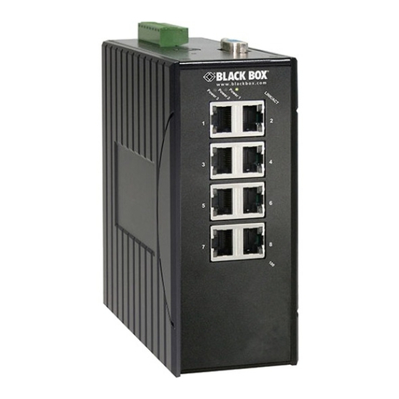
Hardened Managed Ethernet Switches
Use this switch in harsh environments
constrained by space.
Choose from standard, PoE, and PoE+ models.
Order toll-free in the U.S.: Call 877-877-BBOX (outside U.S. call 724-746-5500)
Customer
FREE technical support 24 hours a day, 7 days a week: Call 724-746-5500 or fax 724-746-0746
Support
Mailing address: Black Box Corporation, 1000 Park Drive, Lawrence, PA 15055-1018
Information
Web site: www.blackbox.com • E-mail: info@blackbox.com
LEH908A
LEH1008A
LEH906A-2MMSC LEH1008A-2MMSC LEH1104A-2SFP
LEH906A-2MMST LEH1008A-2MMST LEH1104A-4MMSC LEH1216A
LEH906A-2GSFP
LEH1008A-2SFP
LEH906A-2SFP
LEH1008A-2GSFP
LEH1104A-2GSFP
LEH1104A-4MMST LEH1216A-2GMMSC
BLACK BOX
LEH1208A
LEH1208A-2GMMSC
®
Advertisement
Table of Contents

Related Manuals for Black Box LEH908A


Summary of Contents for Black Box LEH908A
-
Page 1: Black Box
Order toll-free in the U.S.: Call 877-877-BBOX (outside U.S. call 724-746-5500) Customer FREE technical support 24 hours a day, 7 days a week: Call 724-746-5500 or fax 724-746-0746 Support Mailing address: Black Box Corporation, 1000 Park Drive, Lawrence, PA 15055-1018 Information Web site: www.blackbox.com • E-mail: info@blackbox.com... - Page 2 Disclaimer: Black Box Network Services shall not be liable for damages of any kind, including, but not limited to, punitive, consequential or cost of cover damages, resulting from any errors in the product information or specifications set forth in this document and Black Box Network Services may revise this document at any time without notice.
- Page 3 FCC and IC RFI Statements Federal Communications Commission and Industry Canada Radio Frequency Interference Statements This equipment generates, uses, and can radiate radio-frequency energy, and if not installed and used properly, that is, in strict accordance with the manufacturer’s instructions, may cause inter ference to radio communication. It has been tested and found to comply with the limits for a Class A computing device in accordance with the specifications in Subpart B of Part 15 of FCC rules, which are designed to provide reasonable protection against such interference when the equipment is operated in a commercial environment.
-
Page 4: Instrucciones De Seguridad
NOM Statement Instrucciones de Seguridad (Normas Oficiales Mexicanas Electrical Safety Statement) 1. Todas las instrucciones de seguridad y operación deberán ser leídas antes de que el aparato eléctrico sea operado. 2. Las instrucciones de seguridad y operación deberán ser guardadas para referencia futura. 3. -
Page 5: Table Of Contents
Table of Contents Table of Contents 1. Specifications ..................................7 2. Overview ..................................... 10 2.1 Introduction ................................. 10 2.2 Features ..................................12 2.2.1 Features Common to LEH900, LEH1000, LEH1100, and LEH1200 Series Switches ..........12 2.2.2 LEH900 Series Also Has… ..........................13 2.2.3 LEH1000 Series Also Has ........................... - Page 6 Table of Contents 6.6 Switching ..................................45 6.7 Trunking ..................................52 6.8 STP/Ring ..................................54 6.9 VLAN ..................................65 6.10 QoS .................................... 70 6.11 SNMP ..................................73 6.12 802.1x ..................................77 6.13 LLDP ...................................80 6.14 Other Protocols ................................83 7. Command-Line Console Management ..........................90 7.1 Administration Console ...............................90 7.1.1 Exec Mode (View Mode) .............................90 7.1.2 Privileged Exec Mode (Enable Mode) ........................94 7.1.3 Configure Mode (Configure Terminal Mode) ......................97...
-
Page 7: Specifications
• DHCP Client/Server. • Auto-MDI/MDI-X. • Full wire-speed forwarding rate. Connectors LEH908A: (8) RJ-45 10/100; LEH906A-2MMSC: (6) RJ-45 10/100, (2) 100BFX MM SC; LEH906A-2MMST: (6) RJ-45 10/100, (2) 100BFX MM ST; LEH906A-2GSFP: (6) RJ-45 10/100, (2) GE SFP; LEH906A-2SFP: (6) RJ-45 10/100, (2) 10/100 SFP;... - Page 8 Chapter 1: Specifications Technical Specifications (Continued) Indicators Per unit: (3) Power Status LEDs: Power 1, Power 2, Power 3; Per port: 10/100TX, 100FX: LINK/ACT, 10/100/1000TX, 1000SX/LX/1000SX/SFP: LINK/ACT, Speed Power Power input: LEH900 Series, LEH1200 Series: Redundant power inputs: Terminal block: 12 to 48 VDC; DC jack: 12 VDC;...
- Page 9 Chapter 1: Specifications Technical Specifications (Continued) Approvals Standards: IEEE 802.3 10BASE-T, IEEE 802.3u 100BASE-T, 100BASE-FX, IEEE 802.3ab 1000BASE-T, IEEE 802.3z 1000BASE-SX/LX; Safety: UL508; UL160H (ISA 12.1201) Compliance: EMI: FCC Part 15, Class A EN61000-6-4, EN55022, EN61000-3-2, EN61000-3-3, EMS: EN61000-4-2 (ESD standard), EN61000-4-3 (Radiated RFI standards), EN61000-4-4 (Burst standards), EN61000-4-5 (Surge standards),...
-
Page 10: Overview
Table 2-1. Avaiilable models. Part Number Product Name Description LEH900 Series LEH908A 8-Port 10/100 Hardened Managed Ethernet Switch 8 ports 10/100, DC power LEH906A-2MMSC 6-Port 10/100 2-Port 100-Mbps MMSC Hardened 6 ports 10/100, 2 ports 100BFX MM SC, DC power... - Page 11 Chapter 2: Overview Table 2-1 (continued). Available models. Part Number Product Name Description LEH1200 Series (Class 1 Div. 2 ISA 12.12.01 certified for use in hazardous environments) LEH1208A 8-Port 10/100 Mbps Hardened Managed Ethernet 8 ports 10/100, DC power Switch LEH1208A-2GMMSC 8-Port 10/100 Mbps with 2-Port GE MMSC 8 ports 10/100, 2-Port GE, DC power Hardened Managed Ethernet Switch...
-
Page 12: Features
Chapter 2: Overview 2.2 Features 2.2.1 Features Common to LEH900 Series, LEH1000 Series, LEH1100 Series, and LEH1200 Series • Meets NEMA TS1/TS2 Environmental requirements such as temperature, shock, and vibration for traffic control equipment. • Meets EN61000-6-2 & EN61000-6-4 EMC Generic Standard Immunity for industrial environment. •... -
Page 13: Leh900 Series Also Has
Chapter 2: Overview Network Management Methods • Console port access via RS-232 cable (CLI, Command-Line Interface) • Telnet remote access • SNMP agent: - MIB-2 (RFC1213) - Bridge MIB (RFC1493) - RMON MIB (RFC2819) – statistics, history, alarms, and events - VLAN MIB (IEEE802.1Q/RFC2674) - Private MIB - Web browser... -
Page 14: Leh1100 Series Also Has
• -40 to +167° F (-40 to +75° C) operating temperature range. Tested for functional operation @ -40 to +185° F (-40 to +85° C). 2.3 What’s Included Your package includes the following items. If anything is missing or damaged, contact Black Box Technical Support at 724-746-5500 or info@blackbox.com. -
Page 15: Hardware Description
LEH906A-2SFP or Back panel (all models) LEH906A-2MMST LEH906A-2GSFP NOTE: LEH908A (not shown) has (8) RJ-45 ports and no ST, SC, or G1/G2 ports. Figure 2-1. LEH900 Series Hardened Managed Ethernet Switch. Table 2-2. LEH900 Series switches components. Number in Figure 2-1... -
Page 16: Leh1000 Series
Chapter 2: Overview 2.4.2 LEH1000 Series Front panel of Front panel of Back panel (all models) LEH1008A-2MMSC or LEH1008A-2SFP or LEH1008A-2MMST LEH1008A-2GSFP NOTE: LEH1008A (not shown) has (8) RJ-45 ports and no ST, SC, or G1/G2 ports. Figure 2-2. LEH1000 Series Hardened Managed Ethernet Switch. Table 2-2. -
Page 17: Leh1100 Series
Chapter 3: Installation 2.4.3 LEH1100 Series Front panel of Front panel of Back panel (all models) LEH1104A-4MMSC or LEH1104A-2SFP or LEH1104A-4MMST LEH1104A-2GSFP Figure 2-3. LEH1000 Series Hardened Managed Ethernet Switch. Table 2-3. LEH1100 Series switches components. Number in Figure 2-3 Product Name Description Ports G1 and G2... -
Page 18: Leh1200 Series
Chapter 2: Overview 2.4.4 LEH1200 Series Designed for rugged environments, these Hardened Managed Ethernet Switches provide reliable switching in industrial areas. 16-port RJ-45 or 8-port RJ-45 or 8-port RJ-45 or 8-port RJ-45 + 16-port RJ-45 + 8-port RJ-45 + 16-port RJ-45 2 GMMSC/RJ-45 or 2 GMMSC/RJ-45 2 GMMSC/RJ-45... -
Page 19: Indicators On The Leh900, Leh1000, Leh1100, And Leh1200 Series Switches
Chapter 2: Overview 2.4.5 Indicators on the LEH900, LEH1000, LEH1100, and LEH1200 Series Switches Table 2-5. LEH900, LEH1000, and LEH1100 Series Switches Indicators. State Indication Power 1 Steady ON (Green) Power ON Power OFF Power 2 Steady ON (Green) Power ON Power OFF Power 3 Steady ON (Green) -
Page 20: Installation
Chapter 3: Installation 3. Installation 3.1 Selecting a Site for the Switch As with any electric device, you should place the switch where it will not be subjected to extreme temperatures, humidity, or electromagnetic interference. Specifically, the site you select should meet the following requirements: •... -
Page 21: Alarms For Power Failure
Chapter 3: Installation 3.2.3 Alarms for Power Failure There are two pins on the terminal block used for power failure detection. It provides the normally closed output when the power source is active. Use this as a dry contact application to send a signal for power failure detection. Table 3-1a. -
Page 22: Connecting To Your Network
Chapter 3: Installation 3.3 Connecting to Your Network 3.3.1 Cable Type and Length Follow the cable specifications below when connecting the switch to your network. Use appropriate cables that meet your speed and cabling requirements. Table 3-2. Cable specifications. Speed Connector Port Speed Cable... -
Page 23: Switch Management
Chapter 4: Switch Management 4. Switch Management This chapter explains the methods that you can use to configure management access to the switch. It describes the types of management applications and the communication and management protocols that deliver data between your management device (workstation or personal computer) and the system. -
Page 24: Modem Access
Chapter 4: Switch Management 4.2.2 Modem Access You can access the switch’s administration console from a PC or Macintosh using an external modem attached to the console port. The switch management program provides the Console Port screen, accessible from the Basic Management screen that lets you configure parameters for modem access. -
Page 25: Snmp And Rmon Management
Chapter 5: SNMP and RMON Management 5. SNMP and RMON Management This chapter describes the switch’s Simple Network Management Protocol (SNMP) and Remote Monitoring (RMON) capabilities. 5.1 Overview RMON is an abbreviation for the Remote Monitoring MIB (Management Information Base). RMON is a system defined by the Internet Engineering Task Force (IETF) document RFC 2819, which defines how networks can be monitored remotely. -
Page 26: Bridge Groups Supported
Chapter 5: SNMP and RMON Management • RMON Alarm Group – allows a network administrator to define alarm thresholds for any MIB variable. An alarm can be associated with Low Threshold, High Threshold, or both. A trigger can trigger an alarm when the value of a specific MIB variable exceeds or falls below a threshold. -
Page 27: Web-Based Browser Management
Chapter 6: Web-Based Browser Management 6. Web-Based Browser Management The switch provides a Web-based browser interface for configuring and managing the switch. This interface allows you to access the switch using a preferred Web browser. This chapter describes how to configure the switch using its Web-based browser interface. 6.1 Logging on to the Switch Figure 6-1. -
Page 28: Understanding The Browser Interface
Chapter 6: Web-Based Browser Management 6.2 Understanding the Browser Interface The Web browser interface provides groups of point-and-click buttons at the left field of the screen for configuring and managing the switch. Figure 6-2. Browser interface. System System Information, System Name/Password, IP Address, Save Configuration, Firmware Upgrade, Reboot, Logout, User Account, User Privilege Diagnostics Utilization, System Log, Remote Logging, ARP Table, Route Table, Alarm Setting... -
Page 29: System
Chapter 6: Web-Based Browser Management 802.1X Radius Configuration, Port Authentication LLDP LLDP General Settings, LLDP Porsts Settings, LLDP Neighbors, LLDP Statistics Other Protocols GVRP, IGMP Snooping, NTP, GMRP, DHCP Server 6.3 System Figure 6-3. System screen. System Information The System Name, Firmware Version, System Time, MAC Address, Default Gateway, DNS Server, VLAN ID, IP Address, IP Subnet Mask, and Current User Information of Switch. - Page 30 Chapter 6: Web-Based Browser Management Figure 6-4. System name/password screen. System Name/Password 1. System Name: Click in the “System Name” text box. Type a system name if it is blank, or replace the current system name with a new one. 2.
- Page 31 Chapter 6: Web-Based Browser Management Figure 6-5. IP address screen. IP Address 1. IP Address: Click in the “IP Address” text box and type a new address to change the IP Address. 2. IP Subnet Mask: Click in the “IP Subnet Mask” text box and type a new address to change the IP Subnet Mask. 3.
- Page 32 Chapter 6: Web-Based Browser Management Figure 6-6. Save configuration screen. Save Configuration 1. Load Config from TFTP Server: Click in the “TFTP Server” text box and type the TFTP server IP address from where the file will be obtained. Click in the “FILE” text box and type the name of the file that will be obtained. Click the “Load”...
- Page 33 Chapter 6: Web-Based Browser Management Figure 6-7. Firmware Upgrade 1. Filename: Click in the “Filename” text box and type the name of the file that you intend to upgrade to the switch. 2. TFTP Server IP: Click in the “TFTP Server IP” text box and type the TFTP server IP address from where the file will be obtained. 3.
- Page 34 Chapter 6: Web-Based Browser Management FIgure 6-8. Please follow the message on the screen during the firmware upgrade process. Do not turn off the power or perform other functions during this period of time. Figure 6-9. 724-746-5500 | blackbox.com Page 34...
- Page 35 Chapter 6: Web-Based Browser Management Figure 6-10. Firmware has been upgraded successfully to the switch. Reboot the switch after completing the upgrade process. Figure 6-11. 724-746-5500 | blackbox.com Page 35...
- Page 36 Chapter 6: Web-Based Browser Management Figure 6-12. Reboot: Click the “Reboot” button to restart the switch. Figure 6-13. Logout button. Logout: Click on the “Relogin” button to log back into the switch. 724-746-5500 | blackbox.com Page 36...
-
Page 37: Diagnostics
Chapter 6: Web-Based Browser Management 6.4 Diagnostics Figure 6-14. Utilization Click Utilization to view CPU Utilization and Memory Utilization. 724-746-5500 | blackbox.com Page 37... - Page 38 Chapter 6: Web-Based Browser Management Figure 6-15. System Log Click System Log to view system log. Figure 6-16. Remote Logging 1. Status: Click and choose “Enable” or “Disable” to enable or disable the logging of messages that are sent to syslog servers. 2.
- Page 39 Chapter 6: Web-Based Browser Management 4. Add Syslog Server: Click “Add Syslog Server” button to add a syslog server. 5. Syslog Server IP List: Click “Syslog Server IP List” drop-down menu and choose a syslog server IP address from the “Syslog Server IP List”...
- Page 40 Chapter 6: Web-Based Browser Management Route Table Click Route Table to view Route Table. Route Table lists the routes to network destinations. And metrics (distances) are associated with those routes. The Route Table contains information about the topology of the network around it. Figure 6-19.
-
Page 41: Port
Chapter 6: Web-Based Browser Management 6.5 Port Figure 6-20. Configuration 1. Port Description: Click in the “Port” text box select the port. 2. Admin Setting: Choose “Link down” or “Link up” from the “Admin Setting” drop-down list to disable or enable Admin Setting for the port. - Page 42 Chapter 6: Web-Based Browser Management Figure 6-21. Port status. Port Status View the Link Status, Port Description, Speed, Duplex, and Flow Control status for all ports. Figure 6-22. Rate Control 1. Ingress: Click in “Ingress” text box and type a new Rate to change the Ingress Rate Control for the port. Rate Values: 64 kbps, 128 kbps, 192 kbps, …...
- Page 43 Chapter 6: Web-Based Browser Management 2. Egress: Click in “Egress” text box and type a new Rate to change the Egress Rate Control for the port. Rate Values: 64 kbps, 128 kbps, 192 kbps, … , 1792 kbps. 2 Mbps, 3 Mbps, 4 Mbps, … , 100 Mbps. 104 Mbps, 112 Mbps, 120 Mbps, …...
- Page 44 Chapter 6: Web-Based Browser Management Figure 6-24. Per Port VLAN Activities Click ports to view corresponding vlan activities. Port Security Figure 6-25. To configure Port Security: 1. Click on Port/Port Security from the Left navigation window. 2. Select “enable” from the drop-down list next to the port number of the port that you want the Port Security to be configured. 724-746-5500 | blackbox.com Page 44...
-
Page 45: Switching
Chapter 6: Web-Based Browser Management 3. In the “Add MAC Address” text entry box for each port, enter the MAC address of the device that you want to allow access to on this port. You can configure up to 24 MAC address for each port. Click on the “Update Setting”... - Page 46 Chapter 6: Web-Based Browser Management FIgure 6-27. Loopback Detect General Setting: 1. Detect: Choose “Disable (default)” or “Enable” from the “Detect” drop-down list to disable or enable a loopback detection on a port interface. 2. Detect Action: Choose “None (default)” or “Error Disable” from “Detect Action” drop-down list to disable or enable error disable Detect Action on a port interface.
- Page 47 Chapter 6: Web-Based Browser Management For Port Interface: 1. Mode: Choose “Enable” or “Disable (default)” from the “Mode” drop-down list to enable or disable Detect for a port inter- face. 2. Update Setting: Click the “Update Setting” button when you finish the Detect settings for port interface. FIgure 6-28.
- Page 48 Chapter 6: Web-Based Browser Management Figure 6-29. Port Mirroring 1. Mirror From: Choose Mirror From port from Port 1–Port 28. 2. Mirror To: Click “Mirror To” drop-down menu to choose Mirror To port (Port 1–Port 28) from “Mirror To” drop-down list. 3.
- Page 49 Chapter 6: Web-Based Browser Management Figure 6-30. Link State Tracking Group Setting: 1. Enable: Click the check box of a group to enable Link State tracking for a group. Port Setting: 1. Group: Click the “Group” drop-down menu to choose a group for port from the “Group” drop-down list. 2.
- Page 50 Chapter 6: Web-Based Browser Management Figure 6-31. PoE (for LEH1000 Series switches only) PoE System Setting: 1. System Power Budget: Click in the “System Power Budget” text box and type a new system power budget for the switch. 2. Submit: Click on the “Submit” button when you finish PoE System Setting. PoE Port Setting: 1.
- Page 51 Chapter 6: Web-Based Browser Management Figure 6-32. PoE Scheduling (for LEH1000 Series switches only) First click on “Switching” from the main menu. Then click on “PoE” from “Switching.” In the PoE Port Setting, choose “Scheduling” from the “Enable Mode” drop-down list to schedule this port to discover the Powered Device (PD) connected to this port.
-
Page 52: Trunking
Chapter 6: Web-Based Browser Management 6.7 Trunking FIgure 6-33. Port Trunking Static Channel Group: 1. Trunk 1: Click ports to assign ports to Trunk 1. (Maximum 4 ports per Trunk.) LACP Group: 1. Trunk 1: Click ports to assign ports to Trunk 1. (Maximum 4 ports in Trunk 1.) GE Trunking (Gigabit Ports): 1. - Page 53 Chapter 6: Web-Based Browser Management Figure 6-34. LACP Trunking Trunk Configuration: 1. Port: Choose a port from the “Port” drop-down list. 2. Trunk Type: Choose “None,” “Static,” or “LACP” from the “Trunk Type” drop-down list to disable or enable Static or LACP Trunk.
-
Page 54: Stp/Ring
Chapter 6: Web-Based Browser Management 6.8 STP/Ring Figure 6-35. Global Configuration 1. Spanning Tree Protocol: Choose “Enable” or “Disable” from “Spanning Tree Protocol” drop-down list to enable or disable Spanning Tree Protocol. 2. Bridge Priority (0..61440): Click in the “Bridge Priority” text box and type a decimal number between 0 and 61440. 3. - Page 55 Chapter 6: Web-Based Browser Management Figure 6-36. RSTP Port Setting 1. STP Version: Choose “RSTP” from the “STP Version” drop-down list. 2. Port: Choose a port from “Port” drop-down list. 3. Priority(Granularity 16): Click in the “Priority” text box and enter a value between 0 and 240 to set the priority for the port. A higher priority will designate the port to forward packets first.
- Page 56 Chapter 6: Web-Based Browser Management FIgure 6-37. Figure 6-38. MSTP Properties 1. STP Version: Choose “MSTP” from “STP Version” drop-down list. 2. Region Name: Click in the “Region Name” text box to create an MST region and specify a name for it. MST bridges of a region form different spanning trees for different VLANs.
- Page 57 Chapter 6: Web-Based Browser Management 3. Revision Level: Click in the “Revision Level” text box to specify the number for configuration information. The default value of| revision number is 0. 4. Max Hops: Click in the “Max Hops” text box to specify the maximum allowed hops for BPDU in an MST region. This parameter is used by all the instances of the MST.
- Page 58 Chapter 6: Web-Based Browser Management MSTP Instance Setting VLAN Instance Configuration: 1. VLAN Instance Configuration: Click on the “VLAN Instance Configuration” button. The “VLAN Instance Configuration” window appears. 2. VLAN ID: Choose VLAN from the “VLAN ID” drop-down list to simultaneously add multiple VLANs for the corresponding instance of a bridge.
- Page 59 Chapter 6: Web-Based Browser Management Figure 6-42. 724-746-5500 | blackbox.com Page 59...
- Page 60 Chapter 6: Web-Based Browser Management Figure 6-43. MSTP Port Setting Port Instance Configuration 1. Instance ID: Click on the “Instance ID” drop-down menu to choose instance ID from the “Instance ID” drop-down list. 2. Click ports to assign ports to the corresponding instance ID. 3.
- Page 61 Chapter 6: Web-Based Browser Management 4. Update Setting: Click on the “Update Setting” button when you finish MSTP Port Setting. Figure 6-44. Ring Setting Ring State: 1. Click on the “Ring State” drop-down menu from the “Ring State” drop-down list to choose “Enable” or “Disable” to enable or disable Ring State.
- Page 62 Chapter 6: Web-Based Browser Management Figure 6-45. Chain Setting Chain Protocol: 1. Click “Enable” to enable Chain Protocol for ports. 2. Submit: Click on the “Submit” button when you finish Chain Protocol setting. Global Setting: 1. VLAN (1-4094, default: 1): Click in the “VLAN” textbox and specify a VLAN ID number from 1–4094. 2.
- Page 63 Chapter 6: Web-Based Browser Management 5. Submit: Click “Submit” button when you finished Chain Protocol setting. Figure 6-46. Chain Pass-Through Setting 1. Chain pass-through port 1: Choose Chain pass-through port 1 from the “Chain pass-through port 1” drop-down list. 2. Chain pass-through port 2: Click “Choose Chain pass-through port 2 from the “Chain pass-through port 2” drop-down list. 3.
- Page 64 Chapter 6: Web-Based Browser Management Figure 6-47. Advanced Setting Advanced Bridge Configuration: 1. Bridge bpdu-guard cofiguration: Choose “Enable” or “Disable” from the “Bridge bpdu-guard cofiguration” drop-down list to enable or disable the portfast ports to guard against bpdu received for a bridge. When the BPDU Guard feature is set for a bridge, all portfast-enabled ports of the bridge that have bpdu-guard set to default shut down the port on receiving a BPDU.
-
Page 65: Vlan
Chapter 6: Web-Based Browser Management Advanced Per Port Configuration: 1. Portfast configuration/status: Click and choose “Disable” or “Enable” to disable or enable a port as an edge-port to enable rapid transition. 2. Bpdu-guard configuration: Choose “Enable,” “Disable,” or “Default” from the “Bpdu-guard configuration” drop-down list to enable, disable, or default the BPDU Guard feature on a port. - Page 66 Chapter 6: Web-Based Browser Management Figure 6-49. Figure 6-50. 802.1Q VLAN Setting Add VLAN: 1. 802.1Q VLAN Setting: Click “802.1Q VLAN Setting.” The “VLAN Setting” window appears. 2. Add VLAN: Click “Add VLAN” button to create a new VLAN from the “VLAN Setting” window. 3.
- Page 67 Chapter 6: Web-Based Browser Management 2. Tag or Untag: Click on the “Tag or Untag” drop-down menu to choose “Tag” or “Untag” from the “Tag or Untag” drop- down list for a “Hybrid” port. 3. Submit: Click on the “Submit” button when you finish VLAN setting. Figure 6-51.
- Page 68 Chapter 6: Web-Based Browser Management Figure 6-52. 802.1Q Port Setting 1. VLAN Port Setting: Click on the “802.1Q Port Setting.” The “VLAN Port Setting” window appears. 2. Mode: Click on the “Mode” drop-down menu to choose “Access,” “Trunk,” or “Hybrid” from the “Mode” drop-down list for the port.
- Page 69 Chapter 6: Web-Based Browser Management Figure 6-53. Figure 6-54. Port Based VLAN 1. VLAN: Choose the port to be added to or deleted from the VLAN. 2. Select All: Click on the “Select All” button to choose all ports to be added to the VLAN. 3.
-
Page 70: Qos
Chapter 6: Web-Based Browser Management 6.10 QoS Figure 6-55. Global Configuration 1. QoS: From the “QoS” drop-down list, choose “Enable” or “Disable” to enable or disable QoS. 2. Trust: Enable or disable the switch port to trust the CoS (Class of Service) labels of all traffic received on that port. Enable or disable a routed port to trust the DSCP (Differentiated Service Code Point) labels of all traffic received on that port. - Page 71 Chapter 6: Web-Based Browser Management Figure 6-56. 802.1p Priority 1. Priority: From the “Priority” drop-down list, choose 0–3 for VLAN Priority 0–7. 2. Submit: Click on the “Submit” button when you finish 802.1p priority. 724-746-5500 | blackbox.com Page 71...
- Page 72 Chapter 6: Web-Based Browser Management Figure 6-57. DSCP 1. Priority: From “Priority” drop-down list, choose 0–3 for DSCP Priority 0–63. 2. Submit: Click on the “Submit” button when you finish DSCP. 724-746-5500 | blackbox.com Page 72...
-
Page 73: Snmp
Chapter 6: Web-Based Browser Management 6.11 SNMP Figure 6-58. SNMP General Setting 1. SNMP Status: From the “SNMP Status” drop-down list, choose “Enable” or “Disable” to enable or disable SNMP. 2. Description: Click in the “Description” text box and specify a new description for SNMP. 3. - Page 74 Chapter 6: Web-Based Browser Management 11. MAC Notification History Size (1 to 500): Click the text box and type a decimal number to configure the maximum number of entries in the MAC notification history table. The range is 1 to 500. 12.
- Page 75 Chapter 6: Web-Based Browser Management Figure 6-60. Figure 6-61. SNMP v3 Add User: 1. Add User: Click “Add User” button. The “SNMP V3 Setting” window appears. 2. SNMP Version: From the “SNMP Version” drop-down list, choose “SNMPv3 No-Auth,” “SNMPv3 Auth-MD5,” “SNMPv3 Auth-SHA,”...
- Page 76 Chapter 6: Web-Based Browser Management • SNMPv3 Auth-MD5: Add a user using SNMP v3 with authentication. Click in the “Auth. Password” textbox and specify an authentication password. • SNMPv3 Auth-SHA: Add a user using SNMP v3 with authentication. Click in the “Auth. Password” textbox and specify an authentication password.
- Page 77 Chapter 6: Web-Based Browser Management 6.12 802.1x Figure 6-63. Radius Configuration 1. Radius Status: From the “Radius Status” drop-down list, choose “Enable” or “Disable” to globally enable or disable authentication. 2. Update Setting: Click on the “Update Setting” button when you finish Radius Status Setting. Figure 6-64.
- Page 78 Chapter 6: Web-Based Browser Management 3. Radius Server Port: Click in the “Radius Server Port” text box and specify the UDP destination port for authentication requests. The host is not used for authentication if set to 0. 4. Secret Key: Click in the “Secret Key” text box and specify the authentication and encryption key for all radius communications between the Switch and radius server.
- Page 79 Chapter 6: Web-Based Browser Management Figure 6-66. Port Authentication 1. Interface: From the “Interface” drop-down list, choose the port to set port-based authentication. 2. Authentication State: From the “Authentication State” drop-down list, choose “Enable” or “Disable” to enable or disable authentication state.
-
Page 80: Lldp
Chapter 6: Web-Based Browser Management 6.13 LLDP Figure 6-67. LLDP General Settings 1. LLDP: From the “LLDP” drop-down list, choose “Enable” or “Disable” to enable or disable Link Layer Discovery Protocol (LLDP) globally. 2. Holdtime multiplier (2-10): Click in the “Holdtime multiplier” textbox and set the Link Layer Discovery Protocol (LLDP) holdtime multiplier value. - Page 81 Chapter 6: Web-Based Browser Management Figure 6-68. LLDP Ports Settings 1. Transmit: From the “Transmit” drop-down list, choose “Disable” or “Enable” to disallow or allow sending Link Layer Discovery Protocol (LLDP) packets on the interface. 2. Receive: From the “Receive” drop-down list, choose “Disable” or “Enable” to disallow or allow receiving Link Layer Discovery Protocol (LLDP) packets on the interface.
- Page 82 Chapter 6: Web-Based Browser Management Figure 6-69. LLDP Neighbors Click LLDP Neighbors to show Link Layer Discovery Protocol (LLDP) neighbors information. Figure 6-70. LLDP Statistics Click LLDP Statistics to show Link Layer Discovery Protocol (LLDP) statistics. 724-746-5500 | blackbox.com Page 82...
-
Page 83: Other Protocols
Chapter 6: Web-Based Browser Management 6.14 Other Protocols Figure 6-71. GVRP GVRP Global Setting: 1. GVRP: From the“GVRP” drop-down list, choose “Enable” or “Disable” to enable or disable GVRP (GARP VLAN Registration Protocol). 2. Dynamic VLAN Creation: From the “Dynamic VLAN Creation” drop-down list, choose “Enable” or “Disable” to enable or disable Dynamic VLAN Creation. - Page 84 Chapter 6: Web-Based Browser Management 3. GVRP Registration: From the “GVRP Registration” drop-down list, choose “Enable” or “Disable” to enable or disable GVRP Registration to the port. Configuring an IEEE802.1Q trunk port in registration mode allows dynamic creation (if dynamic VLAN creation is enabled), registration, and deregistration of VLANs on the trunk port.
- Page 85 Chapter 6: Web-Based Browser Management 2. Max Response Time (1–240): Click in the “Max Response Time” textbox and specify a new number from 1–240. This determines the maximum amount of time in seconds allowed before sending an IGMP response report. The Max Response Time field allows an entry between 1 and 240 (seconds).
- Page 86 Chapter 6: Web-Based Browser Management Adjust RTC Time: 1. Click in the text box and specify the Year, Month, Day, Hour, Minute, and Second. 2. Update Setting: Click on the “Update Setting” button when you finish Adjust RTC Time. NTP Setting: 1.
- Page 87 Chapter 6: Web-Based Browser Management NOTE: The “Week,” “Hour,” “Minute,” and “Day” fields do not accept alphabetic characters (such as Jan, Feb, sun, mon). They only accept two-digit numbers (0 throught 9). Figure 6-74. GMRP GMRP Global Setting: 1. GMRP: From the “GMRP” drop-down list, choose “Enable” or “Disable” to enable or disable GMRP. 2.
- Page 88 Chapter 6: Web-Based Browser Management Figure 6-75. Figure 6-76. DHCP Server 1. DHCP Binding Table: Click on “DHCP Binding Table” to show DHCP Binding Table. Click on the “Refresh” button to refresh DHCP Binding Table. Click on “DHCP General Setting” to back to DHCP General Setting. 2.
- Page 89 Chapter 6: Web-Based Browser Management 7. Primary DNS: Click in the “Primary DNS” text box and specify the default primary DNS for the DHCP Server. 8. Secondary DNS: Click in the “Secondary DNS” text box and specify the default secondary DNS for the DHCP Server. 9.
-
Page 90: Command-Line Console Management
Chapter 7: Command-Line Management 7. Command-LIne Management The switch provides a command-line console interface for configuration purposes. The switch can be configured either locally through its RS-232 port or remotely via a Telnet session. For the latter, you must specify an IP address for the switch first. This chapter describes how to configure the switch using its console by Command Line. - Page 91 Chapter 7: Command-Line Management Figure 7-2. View mode screen. Basic commands Exec Mode (or View Mode) is the base mode from where users can perform basic commands suchg as: clear, debug, disable, enable, exit, help, logout, no, quit, show, terminal. The CLI contains a text-based help facility.
- Page 92 Chapter 7: Command-Line Management Figure 7-4. Figure 7-5. Login timed out The login session to Exec Mode (or View Mode) has timed out because of an extended period of inactivity (60 seconds) to indi- cate authentication attempt timed out. The switch_a login: prompt will show on the screen. Logon back to Exec Mode (View Mode) At the switch_a login: prompt, type in “root”...
- Page 93 Chapter 7: Command-Line Management Figure 7-6. Exit from Exec Mode (View Mode) At the switch_a> prompt, type in “exit” and press <Enter> to exit from Exec Mode (or View Mode). switch_a>exit Figure 7-7. 724-746-5500 | blackbox.com Page 93...
-
Page 94: Privileged Exec Mode (Enable Mode)
Chapter 7: Command-Line Management 7.1.2 Privileged Exec Mode (Enable Mode) Logon to Privileged Exec Mode (Enable Mode) At the switch_a> prompt, type in “enable” and press <Enter> to log on to Privileged Exec Mode (or Enable Mode). The switch_a# prompt will show on the screen. switch_a>enable Figure 7-8. - Page 95 Chapter 7: Command-Line Management Figure 7-10. At the switch_a# prompt, type in the full or partial command string, then type a question mark “?” to display the command key- words or parameters along with a short description. switch_a#show ? Figure 7-11. 724-746-5500 | blackbox.com Page 95...
- Page 96 Chapter 7: Command-Line Management Figure 7-12. Login timed out The login session to Privileged Exec Mode (or Enable Mode) has timed out because of an extended period of inactivity (60 sec- onds) to indicate authentication attempt timed out. The switch_a login: prompt will show on the screen. Log back on to Exec Mode (View Mode) At the switch_a login: prompt, type in “root”...
-
Page 97: Configure Mode (Configure Terminal Mode)
Chapter 7: Command-Line Management Figure 7-14. 7.1.3 Configure Mode (Configure Terminal Mode) Logon to Configure Mode (Configure Terminal Mode) At the switch_a# prompt, type in “configure terminal” and press <Enter> to log on to Configure Mode (or Configure Terminal Mode). The switch_a(config)# prompt will show on the screen. switch_a#configure terminal Figure 7-15. - Page 98 Chapter 7: Command-Line Management Figure 7-16. Figure 7-17. At the switch_a(config)# prompt, type in the full or partial command string, then type a question mark “?” to display the command keywords or parameters along with a short description. switch_a(config)#show ? 724-746-5500 | blackbox.com Page 98...
- Page 99 Chapter 7: Command-Line Management Figure 7-18. Login timed out The login session to Configure Mode (or Configure Terminal Mode) has timed out because of an extended period of inactivity (60 seconds) to indicate authentication attempt timed out. And the switch_a login: prompt will show on the screen. Logon back to Exec Mode (View Mode) At the switch_a login: prompt, type in “root”...
-
Page 100: System
Chapter 7: Command-Line Management Figure 7-20. 7.2 System System Information, System Name/Password, IP Address, Save Configuration, Firmware Upgrade, Reboot, Logout, User Account, User Privilege System Name/Password System Name: 1. Command Mode: Configure mode Logon to Configure Mode (Configure Terminal Mode). The switch_a(config)# prompt will show on the screen. - Page 101 Chapter 7: Command-Line Management 2. Usage: Use the enable password command to modify or create a password to be used when entering the Enable mode. 3. Command Syntax: enable password PASSWORD PASSWORD specifies the new password of the system. 4. Example: The following example sets the new password mypasswd to switch: switch_a(config)#enable password mypasswd switch_a(config)#...
- Page 102 Chapter 7: Command-Line Management DHCP Client: 1. Command Mode: Interface mode Logon to Configure Mode (Configure Terminal Mode). Then logon to Interface mode. vlan1.1 means vlan 1. The switch_a(config-if)# prompt will show on the screen. switch_a(config)#interface vlan1.1 switch_a(config-if)# 2. Usage: Use get ip dhcp enable command to get IP address through DHCP server.
- Page 103 Chapter 7: Command-Line Management DNS Server: 1. Command Mode: Configure mode Logon to Configure Mode (Configure Terminal Mode). The switch_a(config)# prompt will show on the screen. switch_a(config)# 2. Usage: Use ip dns command to set the IP address of the DNS server. Use the no ip dns command to remove the IP address of the DNS server.
- Page 104 Chapter 7: Command-Line Management Load config to TFTP server: 1. Command Mode: Privileged Exec mode Logon to Privileged Exec Mode (Enable Mode). The switch_a# prompt will show on the screen. switch_a# 2. Usage: Use write config-file command to back up the configuration file to tftp server. 3.
- Page 105 Chapter 7: Command-Line Management 3. Command Syntax: restore default 4. Example: The following example restores the default setting of the switch: switch_a#restore default switch_a# Auto Save: 1. Command Mode: Configure mode Logon to Configure Mode (Configure Terminal Mode). The switch_a(config)# prompt will show on the screen. switch_a(config)# 2.
- Page 106 Chapter 7: Command-Line Management 4. Example: The following example sets the interval WORD (10) when the configuration will be automatically saved to switch: switch_a(config)#service auto-config interval 10 switch_a(config)# Firmware Upgrade 1. Command Mode: Privileged Exec mode Logon to Privileged Exec Mode (Enable Mode). The switch_a# prompt will show on the screen.
- Page 107 Chapter 7: Command-Line Management Figure 7-22. Reboot 1. Command Mode: Privileged Exec mode Logon to Privileged Exec Mode (Enable Mode). The switch_a# prompt will show on the screen. switch_a# 2. Usage: Use reload command to restart switch. 3. Command Syntax: reload 4.
- Page 108 Chapter 7: Command-Line Management 3. Command Syntax: logout 4. Example: The following example specifies to exit from the Exec mode or Privileged Exec mode. switch_a>logout switch_a login: User Account 1. Command Mode: Configure mode Logon to Configure Mode (Configure Terminal Mode). The switch_a(config)# prompt will show on the screen.
-
Page 109: Diagnostics
Chapter 7: Command-Line Management 7.3 Diagnostics Utilization, System Log, Remote Logging, ARP Table, Route Table, Alarm Setting Utilization CPU Utilization: 1. Command Mode: Exec mode Logon to Exec Mode (View Mode). The switch_a> prompt will show on the screen. switch_a> 2. - Page 110 Chapter 7: Command-Line Management 2. Usage: Use the show system-log command to show the system log. 3. Command Syntax: show system-log 4. Example: The following example shows the system log of the switch: switch_a>show system-log Remote Logging Remote Logging: 1. Command Mode: Configure mode Logon to Configure Mode (Configure Terminal Mode).
- Page 111 Chapter 7: Command-Line Management 4. Example: The following example deletes a remote syslog server (IP address: 192.168.1.100) for the switch: switch_a(config)#remote-log del 192.168.1.100 switch_a(config)# ARP Table 1. Command Mode: Privileged Exec mode Logon to Privileged Exec Mode (Enable Mode). The switch_a# prompt will show on the screen. switch_a(config)# 2.
- Page 112 Chapter 7: Command-Line Management Alarm Setting Alarm-trigger if: 1. Command Mode: Configure mode Logon to Configure Mode (Configure Terminal Mode). The switch_a(config)# prompt will show on the screen. switch_a(config)# 2. Usage: Use this command to enable or disable alarm trigger on interface. 3.
-
Page 113: Port
Chapter 7: Command-Line Management 7.4 Port Configuration, Port Status, Rate Control, RMON Statistics, Per Port VLAN Activities Configuration Port Name: 1. Command Mode: Interface mode Logon to Configure Mode (Configure Terminal Mode). Then logon to Interface mode. fe1 means port 1. The switch_a(config-if)# prompt will show on the screen. - Page 114 Chapter 7: Command-Line Management 3. Command Syntax: (no) shutdown 4. Example: The following example shows the use of the shutdown command to shut down the interface fe1 (port 1): switch_a(config)#interface fe1 switch_a(config-if)#shutdown switch_a(config-if)# Duplex: 1. Command Mode: Interface mode Logon to Configure Mode (Configure Terminal Mode). Then logon to Interface mode.
- Page 115 Chapter 7: Command-Line Management 2. Usage: Use flowcontrol on command to enable flow control, and configure the flow control mode for the port. Use the no flowcontrol to disable this function. 3. Command Syntax: flowcontrol on no flowcontrol 4. Example: The following example shows the use of flowcontrol on to the interface fe1 (port 1): switch_a(config)#interface fe1 switch_a(config-if)#flowcontrol on...
- Page 116 Chapter 7: Command-Line Management 3. Command Syntax: show sfp-alarm-trigger IFNAME IFNAME specifies the name of the interface for which status and configuration information is desired. 4. Example: The following example shows the use of show sfp-alarm-trigger to display the information of SFP alarm trigger of the interface ge1 (port G1): switch_a#show sfp-alarm-trigger ge1 Temperature Alarm (Warning) Threshold:...
- Page 117 Chapter 7: Command-Line Management 4. Example: The following example sets high voltage alarm threshold 6 volts for SFP transceiver of interface ge1 (port G1): switch_a(config)#sfp set-vcc ge1 high-alarm 6 switch_a(config)# Tx-bias Alarm (Warning) Threshold: 1. Command Mode: Configure mode Logon to Configure Mode (Configure Terminal Mode). The switch_a(config)# prompt will show on the screen.
- Page 118 Chapter 7: Command-Line Management Rx-pow Alarm (Warning) Threshold: 1. Command Mode: Configure mode Logon to Configure Mode (Configure Terminal Mode). The switch_a(config)# prompt will show on the screen. switch_a(config)# 2. Usage: Use this command to set received optical power alarm (warning) threshold for SFP transceiver. 3.
- Page 119 Chapter 7: Command-Line Management 4. Example: The following example shows the use of rate-control ingress VALUE (10 mega bits) to the interface fe1 (port 1): switch_a(config)#interface fe1 switch_a(config-if)#rate-control ingress 10m switch_a(config-if)# RMON Statistics 1. Command Mode: Exec mode or Privileged Exec mode Logon to Exec Mode (View Mode) or Privileged Exec Mode (Enable Mode).
-
Page 120: Switching
Chapter 7: Command-Line Management 7.5 Switching Bridging, Loopback Detect, Static MAC Entry, Port Mirroring, Link State Tracking, PoE, PoE Scheduling Bridging Aging Time (seconds): 1. Command Mode: Configure mode Logon to Configure Mode (Configure Terminal Mode). The switch_a(config)# prompt will show on the screen. switch_a(config)# 2. - Page 121 Chapter 7: Command-Line Management 4. Example: The following example shows setting storm-control level LEVEL (30) to the interface fe1 (port 1): switch_a(config)#interface fe1 switch_a(config-if)#storm-control level 30 switch_a(config-if)# Broadcast: 1. Command Mode: Interface mode Logon to Configure Mode (Configure Terminal Mode). Then logon to Interface mode.
- Page 122 Chapter 7: Command-Line Management 3. Command Syntax: storm-control multicast enable no storm-control multicast 4. Example: The following example shows setting storm-control multicast enable to the interface fe1 (port 1): switch_a(config)#interface fe1 switch_a(config-if)#storm-control multicast enable switch_a(config-if)# DLF: 1. Command Mode: Interface mode Logon to Configure Mode (Configure Terminal Mode).
- Page 123 Chapter 7: Command-Line Management 2. Usage: Use port-isolation enable command to enable port isolation. Use port-isolation disable command to disable port isolation. 3. Command Syntax: port-isolation (enable | disable) 4. Example: The following example enables port-isolation to the interface fe1 (port 1): switch_a(config)#interface fe1 switch_a(config-if)#port-isolation enable switch_a(config-if)#...
- Page 124 Chapter 7: Command-Line Management 3. Command Syntax: bridge GROUP loopback-detect action (errdisable | none (default)) GROUP <1-1> Bridge-group ID used for bridging. errdisable Enable error disable LoopBack Detect Action on a port interface. none Disable error disable LoopBack Detect Action on a port interface. 4.
- Page 125 Chapter 7: Command-Line Management <1–65535> The loopback detect interval time in seconds. 4. Example: The following example sets loopback detect interval time 10 seconds for bridge GROUP (1): switch_a(config)#bridge 1 loopback-detect interval 10 switch_a(config)# Loopback Detect (Port Interface): 1. Command Mode: Interface mode Logon to Configure Mode (Configure Terminal Mode).
- Page 126 Chapter 7: Command-Line Management 3. Command Syntax: bridge GROUP address MAC forward IFNAME VLANID no bridge GROUP address MAC forward IFNAME VLANID GROUP <1-1> Bridge-group ID used for bridging. MAC the Media Access Control (MAC) address in the HHHH.HHHH.HHHH format. IFNAME the interface on which the frame comes in.
- Page 127 Chapter 7: Command-Line Management The switch_a(config-if)# prompt will show on the screen. switch_a(config)#interface fe1 switch_a(config-if)# 2. Usage: Use this command to define a mirror source port and its direction. Use the no parameter with this command to disable port mirroring by the destination port on the specified source port. 3.
- Page 128 Chapter 7: Command-Line Management Port Setting: 1. Command Mode: Interface mode Logon to Configure Mode (Configure Terminal Mode). Then logon to Interface mode. fe1 means port 1. The switch_a(config-if)# prompt will show on the screen. switch_a(config)#interface fe1 switch_a(config-if)# 2. Usage: Use this command to enable link state tracking for the port.
- Page 129 Chapter 7: Command-Line Management Enable Mode: 1. Command Mode: Interface mode Logon to Configure Mode (Configure Terminal Mode). Then logon to Interface mode. fe1 means port 1. The switch_a(config-if)# prompt will show on the screen. switch_a(config)#interface fe1 switch_a(config-if)# 2. Usage: Use poe enable command to enable this port to discover Powered Device (PD) connected to this port.
- Page 130 Chapter 7: Command-Line Management switch_a(config-if)# Fixed Power Limit (W): 1. Command Mode: Interface mode Logon to Configure Mode (Configure Terminal Mode). Then logon to Interface mode. fe1 means port 1. The switch_a(config-if)# prompt will show on the screen. switch_a(config)#interface fe1 switch_a(config-if)# 2.
- Page 131 Chapter 7: Command-Line Management 4. Example: The following example sets high power priority to the interface fe1 (port 1): switch_a(config)#interface fe1 switch_a(config-if)#poe power-priority high switch_a(config-if)# Power Down Alarm: 1. Command Mode: Interface mode Logon to Configure Mode (Configure Terminal Mode). Then logon to Interface mode.
- Page 132 Chapter 7: Command-Line Management 3. Command Syntax: poe scheduling enable 4. Example: The following example enables PoE scheduling to the interface fe1 (port 1): switch_a(config)#interface fe1 switch_a(config-if)#poe scheduling enable switch_a(config-if)# PoE Schedule: 1. Command Mode: Interface mode Logon to Configure Mode (Configure Terminal Mode). Then logon to Interface mode.
-
Page 133: Trunking
Chapter 7: Command-Line Management 7.6 Trunking Port Trunking, LACP Trunking Port Trunking 1. Command Mode: Interface mode Logon to Configure Mode (Configure Terminal Mode). Then logon to Interface mode. fe1 means port 1. The switch_a(config-if)# prompt will show on the screen. switch_a(config)#interface fe1 switch_a(config-if)# 2. - Page 134 Chapter 7: Command-Line Management 2. Usage: Use static-channel-group command to create a static aggregator, or add a member port to an already-existing static aggregator. Use the no static-channel-group command to detach the port from the static aggregator. 3. Command Syntax: static-channel-group <1-8>...
- Page 135 Chapter 7: Command-Line Management passive Disable initiation of LACP negotiation on a port. 4. Example: The following example enalbes initiation of LACP negotiation on the interface fe1 (port 1) to channel-group 1: switch_a(config)#interface fe1 switch_a(config-if)#channel-group 1 mode active switch_a(config-if)# Clear LACP Counters: 1.
- Page 136 Chapter 7: Command-Line Management 4. Example: The following example sets the LACP port priority 34 of interface fe1 (port 1): switch_a(config)#interface fe1 switch_a(config-if)#lacp port-priority 34 switch_a(config-if)# LACP Timeout: 1. Command Mode: Interface mode Logon to Configure Mode (Configure Terminal Mode). Then logon to Interface mode.
-
Page 137: Stp/Ring
Chapter 7: Command-Line Management no lacp system-priority <1-65535> LACP system priority. The default system priority is 32768. 4. Example: The following example sets the LACP system priority 6700: switch_a(config)#lacp system-priority 6700 switch_a(config)# 7.7 STP/Ring Global Configuration, RSTP Port Setting, MSTP Properties, MSTP Instance Setting, MSTP Port Setting, Ring Setting, Chain Setting, Chain Pass-Through Setting, Advanced Setting Global Configuration STP Version:... - Page 138 Chapter 7: Command-Line Management Use the no form of the command to disable the Multiple Spanning Tree protocol on a bridge. 3. Command Syntax: bridge GROUP multiple-spanning-tree enable no bridge GROUP multiple-spanning-tree enable BRIDGE-FORWARD GROUP <1-1> Bridge group name used for bridging. BRIDGE-FORWARD Puts all ports of the specified bridge into the forwarding state.
- Page 139 Chapter 7: Command-Line Management 2. Usage: Use this command to enable the Spanning Tree protocol on a bridge. Use the no form of the command to disable the Spanning Tree protocol on a bridge. 3. Command Syntax: bridge GROUP spanning-tree enable no bridge GROUP spanning-tree enable BRIDGE-FORWARD GROUP <1-1>...
- Page 140 Chapter 7: Command-Line Management 2. Usage: Use this command to set the hello-time, the time in seconds after which (if this bridge is the root bridge) all the bridges in a bridged LAN exchange Bridge Protocol Data Units (BPDUs). 3. Command Syntax: bridge GROUP hello-time HELLOTIME no bridge GROUP hello-time GROUP <1-1>...
- Page 141 Chapter 7: Command-Line Management 2. Usage: Use this command to set the time (in seconds) after which (if this bridge is the root bridge) each port changes states to learning and forwarding. Use the no parameter with this command to restore the default value. 3.
- Page 142 Chapter 7: Command-Line Management Admin. Path Cost: 1. Command Mode: Interface mode Logon to Configure Mode (Configure Terminal Mode). Then logon to Interface mode. fe1 means port 1. The switch_a(config-if)# prompt will show on the screen. switch_a(config)#interface fe1 switch_a(config-if)# 2. Usage: Use this command to set the cost of a path associated with a bridge-group.
- Page 143 Chapter 7: Command-Line Management LINKTYPE The link type to be assigned to the port. point-to-point Enable rapid transition. shared Disable rapid transition. 4. Example: The following example sets the link-type LINKTYPE (point-to-point) of the interface fe1 (port 1): switch_a(config)#interface fe1 switch_a(config-if)#spanning-tree link-type point-to-point switch_a(config-if)# Autoedge:...
- Page 144 Chapter 7: Command-Line Management 2. Usage: Use spanning-tree edgeport command to set a port as an edge-port and to enable rapid transitions. Use the no spanning-tree edgeport command to set a port to its default state (not an edge-port) and to disable rapid transitions. 3.
- Page 145 Chapter 7: Command-Line Management Then logon to MST Configuration mode. The switch_a(config-mst)# prompt will show on the screen. switch_a(config)#spanning-tree mst configuration switch_a(config-mst)# 2. Usage: Use this command to specify the number for configuration information. The default value of revision number is 0. 3.
- Page 146 Chapter 7: Command-Line Management MSTP Instance Setting Bridge Instance VLAN: 1. Command Mode: MST Configuration mode Logon to Configure Mode (Configure Terminal Mode). Then logon to MST Configuration mode. The switch_a(config-mst)# prompt will show on the screen. switch_a(config)#spanning-tree mst configuration switch_a(config-mst)# 2.
- Page 147 Chapter 7: Command-Line Management INSTANCE_ID Specify the instance ID. BRIDGE_PRIORITY <0-61440> Specify the bridge priority. 4. Example: The following example sets the bridge priority (0) for an MST instance (3) in bridge GROUP (1): switch_a(config)#bridge 1 instance 3 priority 0 switch_a(config)# MSTP Port Setting Bridge-Group Instance:...
- Page 148 Chapter 7: Command-Line Management switch_a(config-if)# 2. Usage: Use this command to set the port priority for a bridge group. The Multiple Spanning Tree Protocol uses port priority as a tiebreak- er to determine which port should forward frames for a particular instance on a LAN, or which port should be the root port for an instance.
- Page 149 Chapter 7: Command-Line Management switch_a(config-if)# Ring Setting Ring state: 1. Command Mode: Configure mode Logon to Configure Mode (Configure Terminal Mode). The switch_a(config)# prompt will show on the screen. switch_a(config)# 2. Usage: Use this command to enable Ring state. Use the no parameter with this command to disable Ring state. 3.
- Page 150 Chapter 7: Command-Line Management Ring-coupling state: 1. Command Mode: Configure mode Logon to Configure Mode (Configure Terminal Mode). The switch_a(config)# prompt will show on the screen. switch_a(config)# 2. Usage: Use this command to enable Ring-coupling state. Use the no parameter with this command to disable Ring-coupling state. 3.
- Page 151 Chapter 7: Command-Line Management The switch_a(config-if)# prompt will show on the screen. switch_a(config)#interface fe1 switch_a(config-if)# 2. Usage: Use this command to set Chain Protocol to an interface. Use the no parameter with this command to revoke Chain Protocol from an interface. 3.
- Page 152 Chapter 7: Command-Line Management 2. Usage: Use this command to set the Switch priority for running chain protocol. Switch with lower priority will run as Master (forwarding) port. Use the no form of the command to restore default value (128). 3.
- Page 153 Chapter 7: Command-Line Management 2. Usage: Use this command to enable Storm Control (broadcast and multicast) for Chain Protocol setting. Use the no form of the com- mand to disable Storm Control (broadcast and multicast) for Chain Protocol setting. 3. Command Syntax: bridge GROUP chain-storm enable no bridge GROUP chain-storm Group = <1-1>...
- Page 154 Chapter 7: Command-Line Management 2. Usage: Use this command to enable the BPDU (Bridge Protocol Data Unit) Guard feature on a bridge. Use the no parameter with this command to disable the BPDU Guard feature on a bridge. When the BPDU Guard feature is set for a bridge, all portfast-enabled ports of the bridge that have bpdu-guard set to default shut down the port on receiving a BPDU.
- Page 155 Chapter 7: Command-Line Management 2. Usage: Use this command to specify the time interval after which a port is brought back up. The range of interval value is from 10 to 1000000. And the default value is 300 seconds. 3. Command Syntax: bridge GROUP spanning-tree errdisable-timeout interval <10-1000000>...
-
Page 156: Vlan
Chapter 7: Command-Line Management fe1 means port 1. The switch_a(config-if)# prompt will show on the screen. switch_a(config)#interface fe1 switch_a(config-if)# 2. Usage: Use this command to enable or disable the BPDU Guard feature on a port. Use the no parameter with this command to set the BPDU Guard feature on a port to default. This command supersedes the bridge level configuration for the BPDU Guard feature. - Page 157 Chapter 7: Command-Line Management Add VLAN/Delete VLAN: 1. Command Mode: VLAN Configure mode Logon to Configure Mode (Configure Terminal Mode). Logon to VLAN Configure Mode. The switch_a(config-vlan)# prompt will show on the screen. switch_a(config)#vlan database switch_a(config-vlan)# 2. Usage: This command enables or disables the state of a particular VLAN on a bridge basis. Specifying the disable state causes all forward- ing over the specified VLAN ID on the specified bridge to cease.
- Page 158 Chapter 7: Command-Line Management Use the no switchport access command to reset the mode of the Layer-2 interface to access (default). 3. Command Syntax: switchport mode access no switchport access 4. Example: The following example sets the switchport mode access of the interface fe1 (port 1): switch_a(config)#interface fe1 switch_a(config-if)#switchport mode access switch_a(config-if)#...
- Page 159 Chapter 7: Command-Line Management Switchport mode trunk: 1. Command Mode: Interface mode Logon to Configure Mode (Configure Terminal Mode). Then logon to Interface mode. fe1 means port 1. The switch_a(config-if)# prompt will show on the screen. switch_a(config)#interface fe1 switch_a(config-if)# 2. Usage: Use switchport mode trunk command to set the switching characteristics of the Layer-2 interface as trunk, and specify only tagged frames.
- Page 160 Chapter 7: Command-Line Management switchport hybrid allowed vlan remove VLANID no switchport hybrid vlan all Allow all VLANs to transmit and receive through the Layer-2 interface. none Allow no VLANs to transmit and receive through the Layer-2 interface. add Add a VLAN to the member set. remove Remove a VLAN from the member set.
- Page 161 Chapter 7: Command-Line Management switchport trunk allowed vlan except VLANID no switchport trunk vlan all Allow all VLANs to transmit and receive through the Layer-2 interface. none Allow no VLANs to transmit and receive through the Layer-2 interface. add Add a VLAN to transmit and receive through the Layer-2 interface. remove Remove a VLAN from transmit and receive through the Layer-2 interface.
-
Page 162: Qos
Chapter 7: Command-Line Management Port Based VLAN Switchport portbase add/remove vlan: 1. Command Mode: Interface mode Logon to Configure Mode (Configure Terminal Mode). Then logon to Interface mode. fe1 means port 1. The switch_a(config-if)# prompt will show on the screen. switch_a(config)#interface fe1 switch_a(config-if)# 2. - Page 163 Chapter 7: Command-Line Management 4. Example: The following example globally enables QoS on the switch: switch_a(config)#mls qos enable switch_a(config)# Trust: 1. Command Mode: Configure mode Logon to Configure Mode (Configure Terminal Mode). The switch_a(config)# prompt will show on the screen. switch_a(config)# 2.
- Page 164 Chapter 7: Command-Line Management Weighted Round Robin: 1. Command Mode: Configure mode Logon to Configure Mode (Configure Terminal Mode). The switch_a(config)# prompt will show on the screen. switch_a(config)# 2. Usage: Use wrr-queue bandwidth command to specify the bandwidth ratios of the transmit queues. 3.
-
Page 165: Snmp
Chapter 7: Command-Line Management 2. Usage: Use mls qos map dscp-queue command to map the DSCP values to a queue. 3. Command Syntax: mls qos map dscp-queue DSCP_VALUE to QUEUE_ID DSCP_VALUE DSCP values. Up to 8 values (separated by spaces). Range is 0-63. QUEUE_ID Queue ID. - Page 166 Chapter 7: Command-Line Management DESCRIPTION The description for SNMP. 4. Example: The following example specifies description (description) for SNMP: switch_a(config)#snmp-server description description switch_a(config)# Location: 1. Command Mode: Configure mode Logon to Configure Mode (Configure Terminal Mode). The switch_a(config)# prompt will show on the screen. switch_a(config)# 2.
- Page 167 Chapter 7: Command-Line Management switch_a(config)# Trap Community Name: 1. Command Mode: Configure mode Logon to Configure Mode (Configure Terminal Mode). The switch_a(config)# prompt will show on the screen. switch_a(config)# 2. Usage: Use this command to specify trap community name for SNMP. Use the no parameter with this command to remove trap community name for SNMP.
- Page 168 Chapter 7: Command-Line Management The switch_a(config)# prompt will show on the screen. switch_a(config)# 2. Usage: Use this command to specify trap host IP address for SNMP. Use the no parameter with this command to remove trap host IP address for SNMP. 3.
- Page 169 Chapter 7: Command-Line Management Use the no snmp-server trap-type enable linkUp command to disable link up trap for SNMP. 3. Command Syntax: (no) snmp-server trap-type enable linkUp 4. Example: The following example enables link up trap for SNMP: switch_a(config)#snmp-server trap-type enable linkUp switch_a(config)# MAC Notification Trap: 1.
- Page 170 Chapter 7: Command-Line Management 4. Example: The following example sets MAC notification trap interval time 10 seconds: switch_a(config)# snmp-server mac-notification interval 10 switch_a(config)# MAC Notification History Size: 1. Command Mode: Configure mode Logon to Configure Mode (Configure Terminal Mode). The switch_a(config)# prompt will show on the screen. switch_a(config)# 2.
- Page 171 Chapter 7: Command-Line Management SNMP v1/v2c Get Community Name: 1. Command Mode: Configure mode Logon to Configure Mode (Configure Terminal Mode). The switch_a(config)# prompt will show on the screen. switch_a(config)# 2. Usage: Use snmp-server community get command to specify and no snmp-server community get command to remove get community name for SNMP.
- Page 172 Chapter 7: Command-Line Management SNMP v3 SNMPv3 No-Auth: 1. Command Mode: Configure mode Logon to Configure Mode (Configure Terminal Mode). The switch_a(config)# prompt will show on the screen. switch_a(config)# 2. Usage: Add a user using snmp v3 with read-only or read-write access mode and without authentication. Use the no form of the com- mand to delete this user.
-
Page 173: 173
Chapter 7: Command-Line Management 4. Example: The following example adds a user (myuser) using snmp v3 with read-write access mode and MD5 authentication (mypassword): switch_a(config)#snmp-server v3-user myuser rw auth md5 mypassword switch_a(config)# SNMPv3 Priv Auth-MD5, SNMPv3 Priv Auth-SHA: 1. Command Mode: Configure mode Logon to Configure Mode (Configure Terminal Mode). - Page 174 Chapter 7: Command-Line Management 2. Usage: Use dot1x system-auth-ctrl command to globally enable authentication. Use no dot1x system-auth-ctrl command to globally disable authentication. 3. Command Syntax: (no) dot1x system-auth-ctrl 4. Example: The following example globally enables authentication: switch_a(config)#dot1x system-auth-ctrl switch_a(config)# Radius Server IP: Radius Server Port: 1.
- Page 175 Chapter 7: Command-Line Management IP-ADDRESS A.B.C.D specifies the IP address of the radius server host. KEY specifies the secret key shared among the radius server and the 802.1x client. 4. Example: The following example specifies the IP address (192.168.1.100) of the remote radius server host and set the secret key (ipi) shared among the radius server and the 802.1x client: switch_a(config)#radius-server host 192.168.1.100 key ipi switch_a(config)#...
- Page 176 Chapter 7: Command-Line Management 4. Example: The following example specifies the retransmit value 12: switch_a(config)#radius-server retransmit 12 switch_a(config)# Port Authentication Authentication State: 1. Command Mode: Interface mode Logon to Configure Mode (Configure Terminal Mode). Then logon to Interface mode. fe1 means port 1. The switch_a(config-if)# prompt will show on the screen.
- Page 177 Chapter 7: Command-Line Management 3. Command Syntax: dot1x port-control autoforce-authorizedforce-unauthorized no dot1x port-control auto Specify to enable authentication on port. force-authorized Specify to force a port to always be in an authorized state. force-unauthorized Specify to force a port to always be in an unauthorized state. 4.
-
Page 178: Lldp
Chapter 7: Command-Line Management 7.12 LLDP LLDP General Settings, LLDP Ports Settings, LLDP Neighbors, LLDP Statistics LLDP General Setting LLDP: 1. Command Mode: Configure mode Logon to Configure Mode (Configure Terminal Mode). The switch_a(config)# prompt will show on the screen. switch_a(config)# 2. - Page 179 Chapter 7: Command-Line Management switch_a(config)# 2. Usage: Use this command to set the transmit interval. This is the interval between regular transmissions of Link Layer Discovery Protocol (LLDP) advertisements. 3. Command Syntax: lldp txinterval <5–32768> <5–32768> TxInterval 5-32768 seconds, default is 30 seconds. 4.
- Page 180 Chapter 7: Command-Line Management 4. Example: The following example sets Link Layer Discovery Protocol (LLDP) Link Aggregation Type Length Value (TLV): switch_a(config)#lldp tlv-global link-aggregation switch_a(config)# LLDP Ports Settings Transmit: 1. Command Mode: Interface mode Logon to Configure Mode (Configure Terminal Mode). Then logon to Interface mode.
- Page 181 Chapter 7: Command-Line Management 3. Command Syntax: (no) lldp rcv-pkt 4. Example: The following example receives Link Layer Discovery Protocol (LLDP) packets on the interface fe1 (port 1): switch_a(config)#interface fe1 switch_a(config-if)#lldp rcv-pkt switch_a(config-if)# Notify: 1. Command Mode: Interface mode Logon to Configure Mode (Configure Terminal Mode). Then logon to Interface mode.
- Page 182 Chapter 7: Command-Line Management 2. Usage: Use this command to configure Link Layer Discovery Protocol (LLDP) Type Length Value (TLV) setting on the interface. Use the no parameter with this command to disable Link Layer Discovery Protocol (LLDP) Type Length Value (TLV) setting on the interface.
-
Page 183: Other Protocols
Chapter 7: Command-Line Management 3. Command Syntax: show lldp neighbors 4. Example: The following example shows Link Layer Discovery Protocol (LLDP) neighbors information: switch_a> show lldp neighbors LLDP Statistics 1. Command Mode: Exec mode or Privileged Exec mode Logon to Exec Mode (View Mode) or Privileged Exec Mode (Enable Mode). The switch_a>... - Page 184 Chapter 7: Command-Line Management set gvrp disable bridge GROUP GROUP Bridge-group ID used for bridging. 4. Example: The following example globally enables GVRP to bridge GROUP (1): switch_a(config)#set gvrp enable bridge 1 switch_a(config)# Dynamic VLAN creation: 1. Command Mode: Configure mode Logon to Configure Mode (Configure Terminal Mode).
- Page 185 Chapter 7: Command-Line Management 4. Example: The following example enables GVRP on the interface fe1 (port 1): switch_a(config)#set port gvrp enable fe1 switch_a(config)# Per port setting: GVRP applicant: 1. Command Mode: Configure mode Logon to Configure Mode (Configure Terminal Mode). The switch_a(config)# prompt will show on the screen.
- Page 186 Chapter 7: Command-Line Management fixed Specify the multicast groups currently registered on the switch are applied to the port, but any subsequent registrations or deregistrations do not affect the port. Any registered multicast groups on the port are not deregistered based on the GARP timers.
- Page 187 Chapter 7: Command-Line Management Use the no ip igmp snooping command to globally disable IGMP Snooping. 3. Command Syntax: (no) ip igmp snooping enable 4. Example: The following example enables IGMP snooping on the switch: switch_a(config)# ip igmp snooping enable switch_a(config)# IGMP version: 1.
- Page 188 Chapter 7: Command-Line Management 2. Usage: Use ip igmp snooping fast-leave command to enable IGMP Snooping fast-leave processing. Fast-leave processing is analogous to immediate leave processing; the IGMP group-membership is removed, as soon as an IGMP leave group message is received with- out sending out a group-specific query.
- Page 189 Chapter 7: Command-Line Management IGMP querier: Max-response-time: 1. Command Mode: Interface mode Logon to Configure Mode (Configure Terminal Mode). Then logon to Interface mode. vlan1.1 means vlan 1. The switch_a(config-if)# prompt will show on the screen. switch_a(config)#interface vlan1.1 switch_a(config-if)# 2. Usage: Use ip igmp query-max-response-time command to configure the maximum response time advertised in IGMP queries.
- Page 190 Chapter 7: Command-Line Management 3. Command Syntax: (no) ip igmp snooping mrouter interface IFNAME IFNAME Specify the name of the interface 4. Example: The following example shows interface fe1 (port 1) statically configured to be a multicast router interface on vlan1.1: switch_a(config)#interface vlan1.1 switch_a(config-if)#ip igmp snooping mrouter interface fe1 switch_a(config-if)#...
- Page 191 Chapter 7: Command-Line Management 3. Command Syntax: ip igmp snooping force-forward LINEnoneall LINE Interface name list, ex: fe1-fe3, fe5. none Not forward multicast packet to any interface. all Forward multicast packet to all interfaces. 4. Example: The following example force forwards multicast packet to interfaces fe1-fe3 and fe5: switch_a(config)# ip igmp snooping force-forward fe1-fe3, fe5 switch_a(config)# Passive Mode Forwarding Port:...
- Page 192 Chapter 7: Command-Line Management 3. Command Syntax: show rtc time 4. Example: The following example shows the use of show rtc time to show RTC time: switch_a>show rtc time Adjust RTC Time: 1. Command Mode: Privileged Exec mode Logon to Privileged Exec Mode (Enable Mode). The switch_a# prompt will show on the screen.
- Page 193 Chapter 7: Command-Line Management 4. Example: The following example enables NTP for the Switch: switch_a(config)#ntp enable switch_a(config)# NTP Server: 1. Command Mode: Configure mode Logon to Configure Mode (Configure Terminal Mode). The switch_a(config)# prompt will show on the screen. switch_a(config)# 2.
- Page 194 Chapter 7: Command-Line Management The switch_a(config)# prompt will show on the screen. switch_a(config)# 2. Usage: Use this command to to set time zone. 3. Command Syntax: clock timezone TIMEZONE TIMEZONE Specifies the time zone. (Please refer the Appendix B) 4. Example: The following example sets time zone (Canada/Yukon): switch_a(config)#clock timezone YST9YDT switch_a(config)#...
- Page 195 Chapter 7: Command-Line Management 3. Command Syntax: clock summer-time TIMEZONE weekday WEEK DAY MONTH HOUR MINUTE WEEK DAY MONTH HOUR MINUTE OFFSET TIMEZONE Specifies the daylight saving timezone. WEEK <1-5> Specifies starting/ending week of daylight savings time. DAY <0-6> Specifies from Sunday to Saturday. MONTH <1-12>...
- Page 196 Chapter 7: Command-Line Management BRIDGE_NAME Bridge instance name. 4. Example: The following example clears the GMRP statistics for VLAN 12 on bridge 1: switch_a#clear gmrp statistics vlanid 12 bridge 1 switch_a# The following example clears the GMRP statistics for all the configured VLANs on bridge 1: switch_a#clear gmrp statistics all bridge 1 switch_a# Set GMRP:...
- Page 197 Chapter 7: Command-Line Management 3. Command Syntax: set port gmrp enable | disable all | IF_NAME enable Enable GMRP on Layer-2 switch port disable Disable GMRP on Layer-2 switch port all All ports added to recently configured bridge IF_NAME Specify the name of the interface. 4.
- Page 198 Chapter 7: Command-Line Management switch_a(config)# 2. Usage: Use this command to set the GMRP forward all option for an interface. 3. Command Syntax: set gmrp fwdall enable | disable IF_NAME IF_NAME Interface name. 4. Example: The following example enables GMRP forwarding on a Layer-2 switch for interface fe1 (port 1): switch_a(config)#set gmrp fwdall enable fe1 switch_a(config)# Set GMRP Timer:...
- Page 199 Chapter 7: Command-Line Management 2. Usage: Use show dhcp-server binding command to display DHCP Server information. 3. Command Syntax: show dhcp-server binding 4. Example: The following example displays DHCP Server information: switch_a#show dhcp-server binding DHCP Server Status: 1. Command Mode: Interface mode Logon to Configure Mode (Configure Terminal Mode).
- Page 200 Chapter 7: Command-Line Management A.B.C.D The default End IP for the DHCP Server. 4. Example: The following example sets the default IP lease block for the DHCP Server: switch_a(config)#dhcp-server range 192.168.1.100 192.168.1.250 switch_a(config)# DHCP Server Subnet-mask: 1. Command Mode: Configure mode Logon to Configure Mode (Configure Terminal Mode).
- Page 201 Chapter 7: Command-Line Management 4. Example: The following example sets the default gateway for the DHCP Server: switch_a(config)#dhcp-server gateway 192.168.1.254 switch_a(config)# DHCP Server DNS: 1. Command Mode: Configure mode Logon to Configure Mode (Configure Terminal Mode). The switch_a(config)# prompt will show on the screen. switch_a(config)# 2.
-
Page 202: Appendix A. Db9 Dce Pin Assignment
Appendix A: DB9 DCE Pin Assignment Appendix A. DB9 DCE Pin Assignment. Pin Number Name RS-232 Signal Name Data Carrier Detect Received Data Transmit Data — Not connected Signal Ground Data Set Ready — Not connected Clear to Send — Not connected 724-746-5500 | blackbox.com Page 202... -
Page 203: Appendix B. Time Zones
Appendix B: Time Zones Appendix B. Time Zones Time Zone Country and City Lists Europe MEZ-1MESZ Europe/Vienna, Europe/Berlin, Europe/Zurich MET-1METDST Africa/Tunis, CET, MET, Europe/Tirane, Europe/Andorra, Europe/Brussels, Europe/Prague, Europe/Copenhagen, Europe/Paris, Europe/Gibraltar, Europe/ Budapest, Europe/Rome, Europe/Vaduz, Europe/Luxembourg, Europe/Malta, Europe/Monaco, Europe/Amsterdam, Europe/Oslo, Europe/Warsaw, Europe/ Belgrade, Europe/Madrid, Africa/Ceuta, Europe/Stockholm, Europe/Vatican, Europe/San_Marino, Arctic/Longyearbyen, Atlantic/Jan_Mayen, Europe/ Ljubljana, Europe/Sarajevo, Europe/Skopje, Europe/Zagreb, Europe/Bratislava,... - Page 204 Appendix B: Time Zones Time Zone Country and City Lists North America PST8PDT America/Los_Angeles, US/Pacific-New, PST8PDT, US/Pacific, SystemV/PST8PDT MST7MDT America/Denver, America/Boise, America/Cambridge_Bay, America/Shiprock, MST7MDT, Navajo, US/Mountain, SystemV/MST7MDT MST7 America/Phoenix, MST, US/Arizona, SystemV/MST7 CST6CDT America/Chicago, America/North_Dakota/Center, America/Menominee, America/Costa_Rica, America/Managua, CST6CDT, US/Central, SystemV/ CST6CDT EST5EDT America/New_York, America/Kentucky/Louisville, America/Kentucky/Monticello,...
- Page 205 Appendix B: Time Zones Time Zone Country and City Lists Oceania CST-9:30CDT Australia/Adelaide, Australia/Broken_Hill, Australia/South, Australia/Yancowinna EST-10EDT Australia/Brisbane, Australia/Lindeman, Australia/Currie, Australia/Melbourne, Australia/Sydney, Australia/ACT, Australia/Canberra, Australia/NSW, Australia/ Queensland, Australia/Tasmania, Australia/Victoria LHT-10:30LHDT Australia/Lord_Howe, Australia/LHI TST-10TDT Australia/Hobart NZST-12NZDT Antarctica/McMurdo, Pacific/Auckland, Antarctica/South_Pole, NZ CIST-12:45CIDT Pacific/Chatham, NZ-CHAT Africa SAST-2...
- Page 206 Appendix B: Time Zones Time Zone Country and City Lists Universal (continued from previous page) UCT11 Pacific/Niue, Pacific/Pago_Pago, Pacific/Apia, Pacific/Midway, Etc/GMT+11, Pacific/Samoa, US/Samoa UCT-1 Africa/Algiers, Africa/Luanda, Africa/Porto-Novo, Africa/Douala, Africa/Bangui, Africa/Ndjamena, Africa/Kinshasa, Africa/Brazzaville, Africa/Malabo, Africa/ Libreville, Africa/Windhoek, Africa/Niamey, Africa/Lagos, Etc/GMT-1 UCT-2 Africa/Gaborone, Africa/Bujumbura, Africa/Lubumbashi, Africa/Tripoli, Africa/ Blantyre, Africa/Maputo, Africa/Kigali, Africa/Lusaka, Africa/Harare, Etc/GMT-2, Libya...
- Page 207 Appendix B: Time Zones Time Zone Country and City Lists Universal (continued from previous page) CST6 America/Regina, America/Swift_Current, Canada/East-Saskatchewan, Canada/ Saskatchewan, SystemV/CST6 EET-2EETDST2 Europe/Bucharest EET-2EETDST3 Europe/Tallinn, Europe/Helsinki, Europe/Riga, Europe/Mariehamn EET-2EETDST2W2K Europe/Istanbul UCT-14 Pacific/Kiritimati, Etc/GMT-14 UCT9:30 Pacific/Marquesas UCT12 Etc/GMT+12 North America (Canada) PST8PDT_CA America/Vancouver, America/Dawson_Creek, America/Whitehorse, America/ Dawson, Canada/Pacific...
- Page 208 About Black Box Black Box provides an extensive range of networking and infrastructure products. You’ll find everything from cabinets and racks and power and surge protection products to media converters and Ethernet switches all supported by free, live 24/7 Tech support available in 60 seconds or less.
Need help?
Do you have a question about the LEH908A and is the answer not in the manual?
Questions and answers