Table of Contents
Advertisement
Quick Links
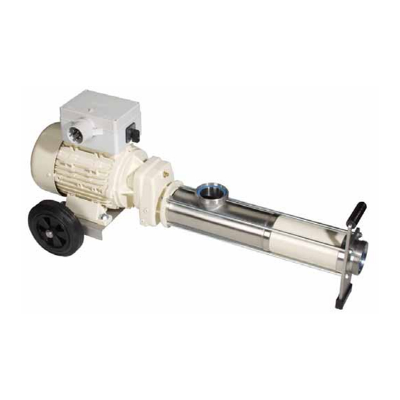
Progressing cavity pump
Operating and maintenance instructions Series AEB1E, AEB2E, AEB2N
with instructions for assembly and
disassembly
Retain the operating instructions for future use!
This is a translation of the original operating instruction.
Refer to the order-specific section of the documentation for operational data, dimensions and other additional
information.
Order No.:
Machine No.:
Edition
BA-2011.01
Print No.
201 100
VM-No.
732.0005 GB
Subject to technical changes!
Important note:
These operating instructions are supplemented with order-specific information.
Construction Types ME, SE, VE
Pump ID No.:
Pump model:
ALLWEILER AG – Bottrop plant
P.O. Box 200123 · 46223 Bottrop
Kirchhellener Ring 77-79 · 46244 Bottrop
Germany
Telephone: +49 (0) 2045-966-60
Fax:
+49 (0) 2045 966-679
E-mail:
service@allweiler.de
Internet:
www.allweiler.com
Advertisement
Table of Contents

Related Manuals for Allweiler AEB1E Series


Summary of Contents for Allweiler AEB1E Series
- Page 1 Refer to the order-specific section of the documentation for operational data, dimensions and other additional information. Order No.: Pump ID No.: Machine No.: Pump model: Edition BA-2011.01 ALLWEILER AG – Bottrop plant Print No. 201 100 P.O. Box 200123 · 46223 Bottrop VM-No. 732.0005 GB Kirchhellener Ring 77-79 · 46244 Bottrop Germany...
- Page 2 These operating and maintenance instructions contain notices from the pump manufacturer. It may be necessary to amend these instructions with instructions from the company that operates the pump. Specific notices about operating and maintaining the overall system in which the pump is integrated are not provided here. These must be provided by the persons who are responsible for planning and constructing the system (system manufacturer).
-
Page 3: Table Of Contents
Table of contents Table of contents 4.2.1 Nameplate ........7 About these instructions ......1 4.2.2 ATEX nameplate ......7 Who should read these 4.2.3 Pump model label ......7 instructions ........1 ... - Page 4 Table of contents Taking the pump out of 11.4 Sectional drawings for SE operation ........14 construction type ....... 29 7.3.1 Stoppage ........14 11.5 Sectional drawings for VE 7.3.2 Measures for longer periods of ...
- Page 5 Table of Figures Table of Figures Fig. 1 Nameplate (example) ...... 7 Fig. 2 ATEX nameplate ......7 Fig. 3 Model code ........7 Fig. 4 Removing the joint clamp ....18 Fig. 5 Removing the joint sleeve ..... 18 ...
- Page 6 Series AEB1E, AEB2E, AEB2N BA-2011.01 732.0005 GB - 201 100 Construction Types ME, SE, VE...
-
Page 7: About These Instructions
About these instructions Who should read these instructions Together with written safety notices, the safety About these instructions symbols are designed to draw attention to These instructions: unavoidable residual hazards during usage of the machine. These residual hazards are are part of the pump, related to: ... -
Page 8: Technical Terms
About these instructions Technical terms 1.4 Technical terms 1.7 Inspection Pump: "Pump" refers to the pump without All pumps are subjected to leak and coupling, drive, or any other components. performance tests before leaving our factory. Only flawlessly operating pumps that meet our Pump unit: "Pump unit"... -
Page 9: Safety
Any other or additional usage is improper country of operation. usage. ALLWEILER will not be liable for any 2.4.2 Operator’s responsibilities resulting damages. Proper use also refers to observation of all... -
Page 10: Personnel Responsibilities
Safety Safety precautions applicable standards and No safety equipment may be removed or taken directives of the country where the out of operation before or during operation of pump is operated the system. ► Provide access to personal protective Before switching on the system, ensure that no equipment. -
Page 11: Unauthorized Conversion And Production Of Spare Parts
Safety Unauthorized conversion and production of spare parts All upstream and downstream parts of the system and operating media like compressed air and hydraulics must be secured against unintentional restarting. When performing any maintenance, Safety glasses inspection, and repair tasks, always shut off Wear safety glasses when working near the the power to the system and secure the switch shaft seal area. -
Page 12: Danger Points
Danger points Hazards when working with the system The machine’s electrical equipment must be Danger points inspected on a regular basis. Loose connections and charred cables must be 3.1 Hazards when working with the removed immediately. system The progressing cavity pump was built Proper earthing must be provided whenever according to the current state of technology there is the potential for electrostatic charges. -
Page 13: Design And Function
Design and function Application and area of usage Design and function Danger! 4.1 Application and area of usage If the pump or pump unit is Progressing cavity pumps are self-priming, operated in potentially explosive rotating displacement pumps suitable for atmospheres, follow the ATEX pumping and metering low-viscosity and high- supplemental instructions. -
Page 14: Dimensions/ Branch Positions/Flanges
Design and function Pump unit design 4.4.4 Dimensions/ 4.4.7 Operation branch positions/flanges Self-priming, rotating displacement pump. The pumping elements are the rotor and the fixed Please refer to the unit drawings for stator. The rotor and stator contact each other dimensions of the pump and pump unit, for at two points of their cross-section. -
Page 15: Transport, Storage, And Disposal
Transport, storage, and disposal Packaging 5.3 Preserving progressing cavity Transport, storage, and disposal pumps and placing them into storage 5.1 Packaging Observe the graphical symbols on the 5.3.1 Preserving packaging. The pump’s suction and pressure sides and Notice! auxiliary connections must be closed with Not necessary with stainless plugs during transport and storage. -
Page 16: Disposal
Transport, storage, and disposal Disposal 5.4 Disposal Plastic parts and elastomers can be contaminated by toxic or radioactive pumped liquids in such a way that cleaning is not adequate. Warning! Danger of poisoning or environmental damage by pumped liquid or oil! ►... -
Page 17: Installation And Connection
Installation and connection Setting up the pump deviations, particularly on the suction side, Installation and connection must be discussed with the factory. 6.1 Setting up the pump Stopping devices must be present in the Pumps of the ME and SE construction types suction and pressure lines. -
Page 18: Safety Device In The Pressure Line
Installation and connection Safety and inspection equipment 6.3.2 Safety device in the pressure 6.3.3 Electrical connections line Caution! Warning! A professional electrician must attach the coupled drive motor’s Driving the pump with a pressure- power supply cable in accordance side liquid column is dangerous due with the connection diagram to the risk of reverse flow. -
Page 19: Operation
Operation Preparing for initial start-up 7.1.3 Checking the direction of Operation rotation 7.1 Preparing for initial start-up Viewed from the drive to the stub shaft, the normal direction of rotation is to the left. The 7.1.1 Filling the pump with liquid suction connection is on the shaft seal side so the shaft seal is balanced. -
Page 20: Checking Pump Capacity
Operation Taking the pump out of operation 7.2.3 Checking pump capacity 7.3 Taking the pump out of Once the drive has reached its operating operation speed, use the vacuum gauge and pressure gauge to check the pump’s inlet and outlet 7.3.1 Stoppage pressures. -
Page 21: Maintenance Cycles And Intervals
Maintenance cycles and intervals Special applications of the pump Maintenance cycles and intervals Maintenance may be necessary for the following parts: Rotor + stator: Wear to the rotor and/or stator is manifested in the form of lower pump capacity and lower pressure. -
Page 22: Preventive Maintenance
9.1.2 Universal joints Universal joints must be lubricated with ALLWEILER special joint oil of type BL or oil 1810/460 from Tribol Lubricants GmbH of Mönchengladbach, Germany. Caution! We have not tested any other... -
Page 23: Maintenance
Maintenance Disassembly and assembly instructions 10.1.1 Disassembling the 10 Maintenance progressing cavity pump For the positions of parts referenced in the Perform the following tasks before following chapters sectional drawings on disassembly: pages 27, 28, 29 and 30. 1. Disconnect the motor’s power cord. 10.1 Disassembly and assembly Prevent the motor from switching on instructions... -
Page 24: Removing The Rotor And Rotor- Side Joint
Maintenance Disassembly and assembly instructions 10.1.3 Removing the rotor and rotor- side joint Remove the rotor and the rotor-side joint after removing the stator (402) Section 10.1.2 page 17. 1. Pull off suction casing (505) over the rotor (401). Caution! The rotor is manufactured to close tolerances. -
Page 25: Removing The Universal Joint Shaft And The Drive-Side Joint
Maintenance Assembling the progressing cavity pump 10.1.4 Removing the universal joint 10.1.6 Removing the mechanical shaft and the drive-side joint seal, single-acting Remove the universal joint shaft and the drive- 1. Pull off from the stub shaft the side joint after removing the stator (402) and mechanical seal casing (214) with the the rotor (401) ... -
Page 26: Installing The Mechanical Seal, Single-Acting
Maintenance Assembling the progressing cavity pump 10.2.1.2 Installing the mechanical seal, Aemasol MO 19 R Spray or paste/ A.C. single-acting Matthes Molykombin UMFT 1 Spray/ 1. Concentrically press the mechanical Klüber Lubrication seal's countering (219) with collar into Unimoly P 5 Powder/ the clean mechanical seal casing Klüber Lubrication... -
Page 27: Installing The Rotor And Rotor-Side Joint
Maintenance Assembling the progressing cavity pump Fig. 8 Pressing in the joint bush 3. Slide joint clamps (306), joint collars (308), and joint sleeve (304) onto the Fig. 7 Clamp sets in inner collar joint shaft (307). 4. Slide the joint shaft (307) into the head 10. -
Page 28: Tightening With Clamping Tool Pok
Figure 11 shows proper tightening under the collar and fill the joint area of the joint clamps (306). with ALLWEILER special joint oil type BL or oil 1810/460 from Tribol Lubricants GmbH of Mönchen- gladbach, Germany. Filling volume see table section 9.1.2 page 16. -
Page 29: Installing The Universal Joint Shaft And The Drive-Side Joint
Maintenance Installing the stator 10.2.4 Installing the universal joint 2. Use the clamp bolts (611) and hexagon nuts (609) to screw into place shaft and the drive-side joint the pressure casing (504), stator (402), suction casing (505), and mechanical 1. Mount the drive-side joint onto the stub seal casing (214). -
Page 30: Spare Parts
Caution! For safety reasons, stock and use only original spare parts provided by Allweiler. Refer to the information provided under Section 2.7 ( page 5)! When ordering spare or reserve parts, always provide the following information: ... -
Page 31: Index Of Spare Parts And Recommended Spare/Reserve Parts
Spare parts Index of spare parts and recommended spare/reserve parts 11.1 Index of spare parts and recommended spare/reserve parts Legend: R = large repair kit r = small repair kit Part No. Description Repair kit Quantity Remarks Clamp set Stub shaft Mechanical seal casing Mechanical seal Joint pin... - Page 32 Spare parts Index of spare parts and recommended spare/reserve parts Part No. Description Repair kit Quantity Remarks Washer Clamp bolt Bracket Support foot Hand grip Circlip Wheel Hexagon nut Hexagon head screw ...
-
Page 33: Sectional Drawings For Me Construction Type
Spare parts Sectional drawings for ME construction type 11.2 Sectional drawings for ME construction type Fig. 13 Sectional drawings for ME construction type 732.0005 GB - 201 100 BA-2011.01 Series AEB1E, AEB2E, AEB2N Construction Types ME, SE, VE... -
Page 34: Sectional Drawing Of Se Construction Type On Leveling Feet
Spare parts Sectional drawing of SE construction type on leveling feet 11.3 Sectional drawing of SE construction type on leveling feet Fig. 14 Sectional drawing of SE construction type on leveling feet Series AEB1E, AEB2E, AEB2N BA-2011.01 732.0005 GB - 201 100 Construction Types ME, SE, VE... -
Page 35: Construction Type
Spare parts Sectional drawings for SE construction type 11.4 Sectional drawings for SE construction type Fig. 15 Sectional drawings for SE construction type 732.0005 GB - 201 100 BA-2011.01 Series AEB1E, AEB2E, AEB2N Construction Types ME, SE, VE... -
Page 36: Sectional Drawings For Ve Measures For Longer Periods Of Construction Type
Spare parts Sectional drawings for VE construction type 11.5 Sectional drawings for VE construction type Fig. 16 Sectional drawings for VE construction type Series AEB1E, AEB2E, AEB2N BA-2011.01 732.0005 GB - 201 100 Construction Types ME, SE, VE... -
Page 37: Causes And Removal Of Operational Faults
Causes and removal of operational faults 12 Causes and removal of operational faults Discuss with the manufacturer any disturbances not contained in the following table or that cannot be traced to the causes listed below. Each possible disturbance is labeled with a letter in the table below. - Page 38 Causes and removal of operational faults Operational disturbances Causes and removal High adhesion between rotor and stator in new condition after long period of downtime Use tool to manually turn pump. Reference arrow on pump to check direction of rotation; reverse ...
-
Page 39: Clearance Certificate
Clearance certificate 13 Clearance certificate Fig. 17 Clearance certificate 732.0005 GB - 201 100 BA-2011.01 Series AEB1E, AEB2E, AEB2N Construction Types ME, SE, VE... -
Page 40: Machinery Directive
Declaration according to EC machinery directive 14 Declaration according to EC machinery directive Declaration of conformity according to EC machinery directive Notice! The following declaration contains neither serial numbers nor signatures. The original declaration with the name of the documentation officer and signatures is included with each pump. -
Page 41: Eg-Konformitätserklärung
Hiermit erklären wir, / We hereby declare / Par la présente, nous déclarons Allweiler AG, Postfach 200123, 46223 Bottrop, Tel. +49 (0)2045-966-60, Fax. +49 (0)2045 966-679 dass die Maschine / that the machine / que le machine Ident Nr. / Ident no / Nº d'ident Benennung / Designation / Désignation... - Page 42 Series AEB1E, AEB2E, AEB2N BA-2011.01 732.0005 GB - 201 100 Construction Types ME, SE, VE...
- Page 43 732.0005 GB - 201 100 BA-2011.01 Series AEB1E, AEB2E, AEB2N Construction Types ME, SE, VE...
- Page 44 Subject to technical changes! ALLWEILER AG P.O. Box 20 01 23 46223 Bottrop Kirchhellener Ring 77-79 46244 Bottrop Germany Tel.: +49 (0)2045 966-60 Fax: +49 (0)2045 966-679 E-mail: service@allweiler.de Internet: http://www.allweiler.com Edition: BA-2011.01 Print No.: 201 100 VM No.:...
Need help?
Do you have a question about the AEB1E Series and is the answer not in the manual?
Questions and answers