Table of Contents
Advertisement
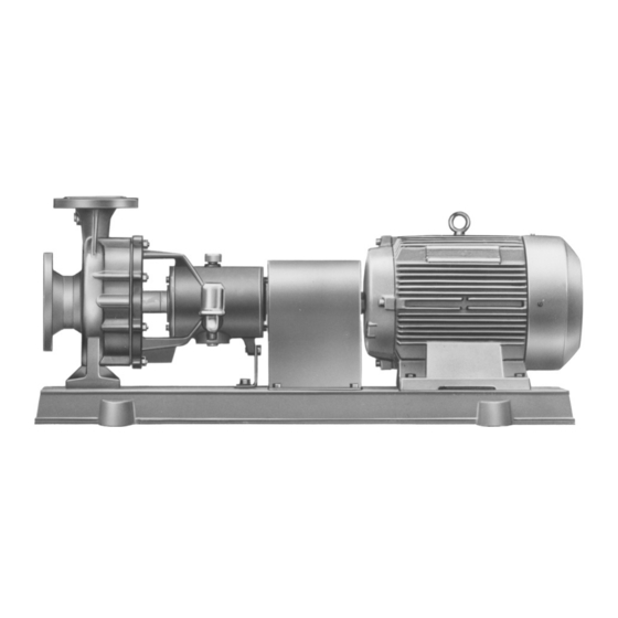
Centrifugal pump with
volute casing
Original Operating Manual
Version
BA-2017.02 en-US
ID-No.
550 115
145-353/0
CNH-B series
ALLWEILER GmbH
Postfach 1140
Allweilerstr. 1
78301 Radolfzell
Germany
Phone: +49 (0) 7732-86-0
Fax: +49 (0) 7732-86-436
Email: service@allweiler.de
Internet: http://www.allweiler.com
We reserve the right to make technical changes.
Read carefully before use.
Save for future use.
Advertisement
Table of Contents
Troubleshooting

Related Manuals for Allweiler CNH-B series


Summary of Contents for Allweiler CNH-B series
- Page 1 Centrifugal pump with volute casing Original Operating Manual CNH-B series Version BA-2017.02 en-US ALLWEILER GmbH ID-No. 550 115 Postfach 1140 145-353/0 Allweilerstr. 1 78301 Radolfzell Germany Phone: +49 (0) 7732-86-0 Fax: +49 (0) 7732-86-436 Email: service@allweiler.de Internet: http://www.allweiler.com We reserve the right to make technical changes.
-
Page 2: Table Of Contents
....... . 29 Installation without foundation ....18 CNH-B series BA-2017.02 en-US... - Page 3 Declaration of conformity according to EC Machine Directives ......51 145-353/0 – 550 115 BA-2017.02 en-US CNH-B series...
- Page 4 ........41 CNH-B series BA-2017.02 en-US...
- Page 5 ........47 145-353/0 – 550 115 BA-2017.02 en-US CNH-B series...
-
Page 6: About This Document
Declaration of conformity Conformity with standards Contents of the declaration of conformity (→ 9.5 Declaration of conformity according to EC Machine Directives, Page 51). Tab. 2 Other applicable documents and their purpose CNH-B series BA-2017.02 en-US 145-353/0 – 550 115... -
Page 7: Warnings And Symbols
Symbols and their meaning Technical terms Term Meaning Sealing medium Medium as seal barrier/buffer fluid or for quenching of shaft seals Auxiliary systems Systems for operating the pump Tab. 5 Technical terms and their meaning 145-353/0 – 550 115 BA-2017.02 en-US CNH-B series... -
Page 8: Safety
(→ order data sheet, technical description). • When using auxiliary systems, ensure that there is a con- tinuous supply of the appropriate medium. CNH-B series BA-2017.02 en-US 145-353/0 – 550 115... -
Page 9: Operator's Obligations
• Obtain the manufacturer's approval prior to carrying out any modification, repair or alterations during the warranty period. • Only use original parts or parts that have been approved by the manufacturer. 145-353/0 – 550 115 BA-2017.02 en-US CNH-B series... -
Page 10: Layout And Function
13 Flow rate 3.1.2 ATEX plate II 2 G c b Tx Technical File No.: EX9 03 09 45910 002 Fig. 2 ATEX plate (example) Explosion protection mark Reference to ATEX additional instructions CNH-B series BA-2017.02 en-US 145-353/0 – 550 115... -
Page 11: Construction
Mechanical seals will always leak a bit, due to the way they work. • Single mechanical seal • Single mechanical seal with quenching • Double mechanical seal with external seal barrier/buffer fluid reservoir (blocking) 145-353/0 – 550 115 BA-2017.02 en-US CNH-B series... -
Page 12: Auxiliary Systems
• pressurized • unpressurized Tab. 8 Blocking - variants and characteristics Closed flow system • Circulates in a closed circuit • unpressurized Tab. 7 Quenching - variants and characteristics CNH-B series BA-2017.02 en-US 145-353/0 – 550 115... -
Page 13: Cooling The Bearing Housing
Cooling the bearing housing If the temperature of the medium being pumped >200 °C, cool the bearing housing. Fig. 9 Heating the housing 3.4.3 Cooling the shaft seal Fig. 8 Cooling the shaft seal 145-353/0 – 550 115 BA-2017.02 en-US CNH-B series... -
Page 14: Transport, Storage And Disposal
3. Dispose of packaging material according to local regula- tions. Fig. 10 Fastening the lifting gear to the pump aggregate Fig. 11 Attaching the lifting gear to the pump Lift the pump/aggregate properly. CNH-B series BA-2017.02 en-US 145-353/0 – 550 115... -
Page 15: Preservation
Remove and dispose of any plastic parts in accordance 5. Make certain that the shaft and the bearing change their with local regulations. rotational position in the process. Dispose of pump according in accordance with local regu- lations. 145-353/0 – 550 115 BA-2017.02 en-US CNH-B series... -
Page 16: Setup And Connection
– ensure that the pump is stable and cannot tip over – for concrete foundations: standard concrete of strength class B 25 CNH-B series BA-2017.02 en-US 145-353/0 – 550 115... -
Page 17: Installing With Foundations
6. Use the integrated spirit levels to check that the pump is level end to end and side to side with max. 1mm/m allow- able tilt. 7. Repeat procedure until the base plate is correctly aligned. 145-353/0 – 550 115 BA-2017.02 en-US CNH-B series... -
Page 18: Installation Without Foundation
– cold/warm – empty/full – unpressurized/pressurized – shift in position of flanges 2. Ensure that pipe supports have permanent low-friction properties and will not seize up through corrosion. CNH-B series BA-2017.02 en-US 145-353/0 – 550 115... -
Page 19: Specifying Nominal Diameters
1. Clean all piping components and armatures prior to assem- bly. 2. Ensure that no flange gaskets protrude inwards. 3. Remove blind flanges, plugs, protective foils and/or protec- tive paint on flanges. 145-353/0 – 550 115 BA-2017.02 en-US CNH-B series... -
Page 20: Installing Auxiliary Piping
– height shift: by means of metal shims 3. Tighten the support foot bolts to the base plate, making cer- tain that the bearing bracket is not distorted in the process. CNH-B series BA-2017.02 en-US 145-353/0 – 550 115... -
Page 21: Precisely Align The Coupling
Position the straightedge across both halves of the coupling. – If there is a visible gap under the straightedge on the outer diameter, align the motor (→ 5.9 Aligning the motor, Page 22). 145-353/0 – 550 115 BA-2017.02 en-US CNH-B series... -
Page 22: Aligning The Motor
(2) and tighten the lock nut (4). 4. Tighten the hexagon head bolts (1). 5. Check the alignment. 6. Repeat alignment procedure if there is still a vertical mis- alignment. 7. Tighten the motor bolts. CNH-B series BA-2017.02 en-US 145-353/0 – 550 115... -
Page 23: Operation
5. Fill the reservoir and tip it up. 6. Repeat step 5 until the reservoir remains two thirds filled with lubricating oil. 7. Refit the vent screw. 145-353/0 – 550 115 BA-2017.02 en-US CNH-B series... -
Page 24: Preparing Auxiliary Systems (If Available)
(→ 9.2.2 Parameters for auxiliary sys- tems, Page 43). Heating the housing 1. Install the connections and properly install the heating (→ manufacturer's specifications). 2. Ascertain the heating parameters (→ 9.2.2 Parameters for auxiliary systems, Page 43). CNH-B series BA-2017.02 en-US 145-353/0 – 550 115... -
Page 25: Start-Up
Do not open the pressure-side armature beyond the oper- ating point. NOTE Material damage caused by overheating! Do not operate the pump for long periods with the pressure- side fitting closed. Observe the minimum flow rate (→ order data sheet). 145-353/0 – 550 115 BA-2017.02 en-US CNH-B series... -
Page 26: Switching Off
– – Remains liquid, non-corrosive – Remains liquid, Empty the corrosive pump and containers. Treat the pump and containers with preser- vative. Tab. 11 Measures depending on nature of pumped medium CNH-B series BA-2017.02 en-US 145-353/0 – 550 115... -
Page 27: Start-Up Following A Shutdown Period
1. Completely open the suction-side armature. 2. Open the pressure-side armature to an extent that the stand-by pump reaches its operating temperature and is heated through evenly (→ 6.2.1 Switching on, Page 25). 145-353/0 – 550 115 BA-2017.02 en-US CNH-B series... -
Page 28: Maintenance
2. For oil changes, unscrew the plug on the bearing housing and drain the oil at operating temperature into a suitable container. 3. Refit the plug and fill with lubricating oil (→ 6.1.3 Lubricating the bearings, Page 23). CNH-B series BA-2017.02 en-US 145-353/0 – 550 115... -
Page 29: Mechanical Seals
Observe the manufacturer's specifications (e.g. for the motor, coupling, mechanical seal, blocking pressure sys- tem, cardan shaft, drives, belt drive etc.). 145-353/0 – 550 115 BA-2017.02 en-US CNH-B series... -
Page 30: Returning The Pump To The Manufacturer
When disassembling take note of the following: – Precisely mark the assembly orientation and position of all components before disassembly. – Dismantle components concentrically without canting. – Disassemble pump (→ Sectional drawing). CNH-B series BA-2017.02 en-US 145-353/0 – 550 115... -
Page 31: Ordering Replacement Parts
Have the following information ready to hand for ordering replacement parts (→ Type plate): – Short designation of the pump – Pump number – Year of manufacture – Part number – Designation – Quantity 145-353/0 – 550 115 BA-2017.02 en-US CNH-B series... -
Page 32: Troubleshooting
Excessive amount of gas: pump is Consult with manufacturer. cavitating – – – – – – Pumped medium temperature too high: Increase supply pressure. pump is cavitating Lower the temperature. Inquire with manufacturer. CNH-B series BA-2017.02 en-US 145-353/0 – 550 115... - Page 33 – – – Disassemble pump. Hydraulic components of the pump dirty, clotted or encrusted Clean the components. – – – – – – Faulty antifriction bearing in bearing Replace antifriction bearings. housing 145-353/0 – 550 115 BA-2017.02 en-US CNH-B series...
-
Page 34: Tab. 15 Troubleshooting List
Coupling unit worn Replace coupling unit and realign. – – – – – Motor running on 2 phases Check fuse and replace it if necessary. Check cable connections and insulation. Tab. 15 Troubleshooting list CNH-B series BA-2017.02 en-US 145-353/0 – 550 115... -
Page 35: Appendix
Shaft sealing ring 420.3 Shaft sealing ring 433.1 Mechanical seal 433.2 Mechanical seal 452.1 Gland 456.1 Neck bushing 461.1 Gland packing 471.1 Seal cover 471.2 Seal cover 507.1 Oil thrower 509.1 Intermediate ring 145-353/0 – 550 115 BA-2017.02 en-US CNH-B series... -
Page 36: Tab. 17 Designations Of Components Listed With Part Numbers
Stud bolt 902.101 Stud bolt 902.2 Stud bolt 902.3 Stud bolt 902.4 Stud bolt 902.5 Stud bolt 903.1 Screwed plug 903.4 Screwed plug 904.1 Grub screw 908.1 Jacking screw 914.3 Cheese head screw CNH-B series BA-2017.02 en-US 145-353/0 – 550 115... -
Page 37: Overview Sectional Drawing
Appendix 9.1.3 Overview sectional drawing Fig. 21 CNH-B with single mechanical seal 145-353/0 – 550 115 BA-2017.02 en-US CNH-B series... -
Page 38: Fig. 22 Dust Protection Version In Category 2D
Appendix Fig. 22 Dust protection version in category 2D 1) With sizes 45 + 60 2) With sizes 70 + 75 CNH-B series BA-2017.02 en-US 145-353/0 – 550 115... -
Page 39: Variants
Fig. 25 CNH-B - version with axially-centered feet CNH-B – heating on both sides Fig. 24 CNH-B - version with cooling of bearing housing Fig. 26 CNH-B – heating on both sides 145-353/0 – 550 115 BA-2017.02 en-US CNH-B series... -
Page 40: Tab. 18 Dimension A For Ku-Type Mechanical Seals According To En 12756
Dimension A (end of mechanical seal to face of shaft protection sleeve) Bearing bracket Dimension A [mm] 45, 45/1 40,5 Tab. 18 Dimension A for KU-type mechanical seals according to EN 12756 CNH-B series BA-2017.02 en-US 145-353/0 – 550 115... -
Page 41: Tab. 19 Dimension A For Mechanical Seals According To En 12756
Dimension A [mm] diameter 45, 45/1 65,5 83,5 73,5 73,5 Tab. 19 Dimension A for mechanical seals according to EN 12756 Fig. 31 Single mechanical seal with stationary spring and quench 145-353/0 – 550 115 BA-2017.02 en-US CNH-B series... -
Page 42: Coupling Guard
Dimension A (end of mechanical seal to face of shaft protection sleeve) Bearing bracket Dimension A [mm] 45, 45/1 40,5 Tab. 20 Dimension A for mechanical seals according to EN 12756 CNH-B series BA-2017.02 en-US 145-353/0 – 550 115... -
Page 43: Technical Specifications
Tab. 25 Operating parameters for heating chamber Cooling the bearing housing Pressure Volume flow Temperature [°C] [bar] [l/h] at ingress at egress ≤ 10 100–200 10–20 < 50 Tab. 26 Parameters for coolant 145-353/0 – 550 115 BA-2017.02 en-US CNH-B series... -
Page 44: Sound Pressure Level
A4–80/8.8 Tab. 27 Sound pressure level 920.5 A4–80/8.8 M20 x 1.5 1.4408/1.4517/ 922.1 M24 x 1.5 1.4301 M30 x 1.5 Tab. 28 Tightening torques 1) not valid for pumps with packing gland CNH-B series BA-2017.02 en-US 145-353/0 – 550 115... -
Page 45: Lubricants
Cleaning agents Foodstuffs and drinking e.g. spirit, Ritzol 155, strong water sector alkaline soapy solution, steam jet (for individual components only) Other Benzine, wax solvents, diesel, paraffin, alkaline cleaners Tab. 30 Cleaning agents 145-353/0 – 550 115 BA-2017.02 en-US CNH-B series... -
Page 46: Height Offset To Align The Motor Using Adjusting Screw
– 1,42 – 0,63 – 1,44 – 0,65 – 1,46 – 0,67 – 1,48 – 0,69 1,50 1 full turn – 0,71 Tab. 31 Height setting on the adjusting screw – 0,73 CNH-B series BA-2017.02 en-US 145-353/0 – 550 115... -
Page 47: Flange Loads According To Iso 5199
2400 10900 9500 5200 125–250 9700 6100 3450 14000 12800 7300 125–315 8500 5400 2950 12500 11400 6700 125–400 8600 5400 2950 12700 11600 6850 150–200 12600 8000 4800 17700 16600 9600 145-353/0 – 550 115 BA-2017.02 en-US CNH-B series... -
Page 48: Temperature
50 100 150 200 250 300 350 400 450 Fig. 35 Correction factor M and operating temperature Non alloyed steel cast Austenitic steel cast Spheroidal iron GGG 40.3 Gray cast iron GG 25 CNH-B series BA-2017.02 en-US 145-353/0 – 550 115... -
Page 49: Spare Parts For 2 Years Of Continuous Operation According To Din 24296
Seals for pump housing (set) various 150 % Other seals (set) Tab. 33 Replacement parts for 2 years of continuous operation 1) Can be purchased as a mechanical unit (BG) or as a sales unit (VG). 145-353/0 – 550 115 BA-2017.02 en-US CNH-B series... -
Page 50: Declaration Of Harmlessness
The sender is liable for all damages caused by unmarked decontaminations of the returned object. Place, date Signature Stamp Tab. 34 Declaration of harmlessness CNH-B series BA-2017.02 en-US 145-353/0 – 550 115... -
Page 51: Declaration Of Conformity According To Ec Machine Directives
EC declaration of conformity according to machine directive, appendix II A ALLWEILER GmbH, Postfach 1140, 78301 Radolfzell, Germany; Tel. +49 (0)7732 86-0, Fax. +49 (0)7732 86-436, hereby declare that, when the conditions in the operating manual are observed, the pump unit / pump:... - Page 52 Appendix CNH-B series BA-2017.02 en-US 145-353/0 – 550 115...
Need help?
Do you have a question about the CNH-B series and is the answer not in the manual?
Questions and answers