Table of Contents
Advertisement
Quick Links
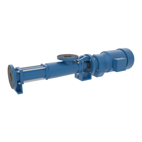
Progressive Cavity Pump
Operating instructions
Version
BA-2020.05 en-US
176-982/0
ID-No.
260371
Series:
AE(B).E, AE(B).F, AE(B).H,
AE(B).L, AE(B).N, AE.V,
AED(B).E, AED(B).N
Designs:
DE, ID, IE, RG, ZD, ZE
ALLWEILER GmbH
Postfach 200123
Kirchhellener Ring 77-79
46244 Bottrop
Germany
Phone: +49 (0) 2045-966-60
Fax: +49 (0) 2045 966-679
E-mail: service@allweiler.de
Internet: http://www.allweiler.com
We reserve the right to make technical changes.
Read carefully before use.
Retain for future use.
Advertisement
Table of Contents
Troubleshooting


Need help?
Do you have a question about the AEB.E Series and is the answer not in the manual?
Questions and answers