Table of Contents
Advertisement
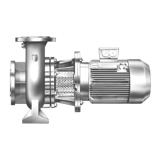
Centrifugal Pump with
Volute Casing
Operating manual
Version
BA-2006.05
Print-No.
550 148
VM-No.
468.0005 GB
NB / CLB series
ALLWEILER AG • Werk Radolfzell
Postfach 1140
Allweilerstr. 1
78301 Radolfzell
Germany
Phone: +49 (0) 7732-86-0
Fax: +49 (0) 7732-86-436
E-mail: info@allweiler.com
Internet: http://www.allweiler.com
We reserve the right to make technical changes.
Advertisement
Table of Contents
Troubleshooting

Related Manuals for Allweiler NB Series


Summary of Contents for Allweiler NB Series
- Page 1 Centrifugal Pump with Volute Casing Operating manual NB / CLB series Version BA-2006.05 ALLWEILER AG • Werk Radolfzell Print-No. 550 148 Postfach 1140 VM-No. 468.0005 GB Allweilerstr. 1 78301 Radolfzell Germany Phone: +49 (0) 7732-86-0 Fax: +49 (0) 7732-86-436 E-mail: info@allweiler.com Internet: http://www.allweiler.com...
-
Page 2: Table Of Contents
......16 9.1.4 Sectional drawings of the NB series ..31 Planning the pipes . - Page 3 Table of contents 9.2.3 Parameters for auxiliary systems ... 38 9.2.4 Sound pressure levels ..... . . 38 9.2.5 Tightening torques .
- Page 4 Table of contents List of figures Fig. 28 U3...D – Unbalanced mechanical seal – sizes with diameter 40 at the shaft seal ... 36 Fig. 1 Type plate (example) ......10 Fig.
- Page 5 ........29 Tab. 14 Designations of components of the NB series according to part numbers ....29 Tab.
-
Page 6: About This Document
About this document About this document This manual • Is part of the pump • Applies to the afore-mentioned pump series • Describes safe and appropriate operation during all oper- ating phases Target groups Target group Duty Operating company Keep this manual available at the site of operation of the system, including for later use. -
Page 7: Warnings And Symbols
About this document Warnings and symbols Warning Risk level Consequences of disregard Immediate acute risk Death, grievous bodily harm DANGER Potentially acute risk Death, grievous bodily harm WARNING Potentially hazardous situation Minor bodily harm CAUTION Potentially hazardous situation Material damage CAUTION Tab. -
Page 8: Safety
Safety Safety The manufacturer does not accept any liability caused by General safety instructions disregarding the entire documentation. Take note of the following regulations before carrying out any work. Intended use 2.2.1 Product safety • Only use the pump for pumping the agreed pumped media The pump has been constructed according to the latest tech- (→... -
Page 9: Obligations Of The Operating Company
Safety 2.2.2 Obligations of the operating company 2.2.3 Obligations of personnel Safety-conscious operation • All directions given on the pump must be followed (and kept legible), e.g. the arrow indicating the direction of rotation • Only operate the pump if it is in perfect technical condition and the markings for fluid connections. -
Page 10: Layout And Function
Pump type code (example) NB or CLB series Pressure flange DN [mm] Nominal impeller diameter [mm] Fig. 1 Type plate (example) Hydraulic number (NB series only) Pump type Actual impeller diameter [mm] Year of manufacture Shaft seal Differential head Material key... -
Page 11: Layout
Layout and function Layout Fig. 4 NB/CLB layout Impeller Motor bell housing Stub shaft Volute casing Motor with fixed bearing at drive end Shaft seal part Shaft seals Only one of the following shaft seals can be used. 3.3.1 Mechanical seals Mechanical seals have functional leaks. -
Page 12: Auxiliary Systems
Layout and function Auxiliary systems 3.4.1 Sealing systems Quenching Fig. 5 Single mechanical seal with quenching (sketch) Seal Quench space Quench medium connection The pressure of the pumped medium is higher than the pres- sure of the sealing medium during quenching. The seal sur- faces are lubricated by the pumped medium. -
Page 13: Transport, Storage And Disposal
Transport, storage and disposal Transport, storage and disposal Transport Preservation For weight specifications (→ documents for the particular Not necessary for non-rusting materials order). 4.1.1 Unpacking and inspection on delivery CAUTION 1. Unpack the pump/aggregate on delivery and inspect it for transport damage. -
Page 14: Removing The Preservative
Transport, storage and disposal Removing the preservative Disposal Only necessary for pumps treated with preservative Plastic parts can be contaminated by poisonous or radioac- tive pumped media to such an extent that cleaning is insuf- ficient. WARNING WARNING Risk of poisoning from preservatives and cleaning agents Risk of poisoning and environmental damage by the in the foodstuffs and drinking water sector! pumped medium or oil! -
Page 15: Setup And Connection
Setup and connection Setup and connection For pumps in explosion hazard areas (→ ATEX additional 5.1.4 Installing the heat insulation instructions). Only necessary to maintain the temperature of the pumped medium CAUTION CAUTION Material damage caused by dirt! Do not remove the transport seals until immediately before Material damage caused by overheating! setting up the pump. -
Page 16: Setting Up The Pump Aggregate
Setting the pump aggregate on the foundation motor bell housing (341.xx): ✔ Implements, tools and materials: – Undo the bolts/nuts (901.10/920.10) for this pur- pose (→ 9.1.4 Sectional drawings of the NB series, – Foundation bolts (→ setup drawing) Page 31). –... -
Page 17: Specifying Nominal Diameters
Setup and connection 5.4.3 Specifying nominal diameters 5.4.6 Provide safety and control devices (recommended) Keep the flow resistance in the pipes as low as possible. Avoid impurities 1. Integrate a filter in the suction pipe. 1. Make sure the nominal suction pipe diameter is not smaller 2. -
Page 18: Connecting The Pipes
Setup and connection Connecting the pipes Electrical connection 5.5.1 Installing auxiliary pipes (if available) DANGER Follow the manufacturers' specifications for any available auxiliary systems. Risk of death due to electric shock! Have all electrical work carried out by qualified electricians 1. -
Page 19: Operation
Operation Operation For pumps in explosion hazard areas (→ ATEX additional 6.1.4 Filling and bleeding instructions). ✔ Auxiliary systems ready for operation Preparations for the initial start-up WARNING 6.1.1 Identifying the pump type Risk of injury and poisoning due to hazardous pumped media! Identify the pump type (→... -
Page 20: Start-Up
Operation Start-up 6.2.2 Switching off ✔ Pressure-side armature closed (recommended) 6.2.1 Switching on ✔ Pump aggregate set up and connected properly WARNING ✔ All connections stress-free and sealed ✔ Any available auxiliary systems are ready for operation Risk of injury due to hot pump parts! ✔... -
Page 21: Start-Up Following A Shutdown Period
Operation Start-up following a shutdown period Take the following measures whenever the pump is shut down: 1. If the pump is shut down for over 1 year, take the following measures before starting it up again: Pump is Measure ...shut down Take measures depending on Shutdown period Measure... -
Page 22: Maintenance
Maintenance Maintenance For pumps in explosion hazard areas (→ ATEX additional Maintenance instructions). The stub shaft of the pump and the motor shaft are con- Trained service technicians are available for fitting and nected firmly together. Notes on maintenance of the bear- repair jobs. -
Page 23: Dismounting
Maintenance Dismounting 7.3.1 Returning the pump to the manufacturer ✔ Pump unpressurized DANGER ✔ Pump completely empty ✔ Electrical connections isolated and motor secured against Risk of injury due to running pump! switch-on Do not touch the running pump. ✔ Pump cooled down Do not carry out any work on the running pump. -
Page 24: Removal Of The Flanged Motor
Maintenance 7.3.3 Removal of the flanged motor Installation of the flanged motor Fig. 9 Widening the stub shaft Fig. 8 Widening the stub shaft Cheese head screw Cheese head screw Stub shaft Stub shaft Shaft key groove of the motor shaft Shaft key groove of the motor shaft Tighten the jack screw with a screwdriver without applying Tighten the jack screw with a screwdriver without applying... -
Page 25: Ordering Spare Parts
Maintenance Ordering spare parts For trouble-free replacement in the event of faults, we rec- ommend keeping entire slide-in units or spare pumps avail- able on site. The application guidelines conforming to DIN 24296 rec- ommend provisioning for two years of continuous use (→... -
Page 26: Troubleshooting
Troubleshooting Troubleshooting For faults which are not specified in the following table or can- not be traced back to the specified causes, please consult the manufacturer. Possible faults are identified by a fault number in the table below. This number identifies the respective cause and rem- edy in the troubleshooting list. - Page 27 Troubleshooting Fault number Cause Remedy – – – – – Viscosity or specific gravity of the pumped Consult the manufacturer. medium outside the range specified for the pump – – – – – – Geodetic differential head and/or pipe flow Remove sediments from the pump resistances too high and/or pressure pipe.
-
Page 28: Tab. 12 Troubleshooting List
Troubleshooting Fault number Cause Remedy – – – – – – – – Lubricant: too much, not enough or Reduce, top up or replace the lubricant. unsuitable – – – – – – – Connecting bolts not tightened properly Tighten the connecting bolts. –... -
Page 29: Appendix
902.08 Stud bolt Pressure gauge Tab. 13 Abbreviations of the connection designations 903.01 Screw plug 903.02 Screw plug 9.1.2 Part numbers and designations of the NB series 903.04 Screw plug Part no. Designation 904.05 Grub screw 102.01 Volute casing 914.01 Cheese head screw 108.01... -
Page 30: Part Numbers And Designations Of The Clb
Appendix 9.1.3 Part numbers and designations of the CLB series Part no. Designation 102.1 Volute casing 161.1 Housing cover 211.1 Stub shaft 230.1 Impeller 341.1 Motor bell housing 400.1 Gasket 400.2 Gasket 411.1 Seal ring 411.2 Seal ring 433.1 Mechanical seal 509.1 Intermediate ring 509.2... -
Page 31: Sectional Drawings Of The Nb Series
Appendix 9.1.4 Sectional drawings of the NB series Fig. 10 U3...D – Unbalanced mechanical seal – sizes with diameter 16 at the shaft seal Fig. 11 Attachment of the guard sheet to the motor bell housing 468.0005 GB – 550 148 BA-2006.05... - Page 32 Appendix Fig. 12 U3...D – Unbalanced mechanical seal – sizes with diameter 24 and 30 at the shaft seal Fig. 13 Housing cover version for sizes 2/40-250/01 and 2/50-250/01 Fig. 15 Version with intermediate ring, sizes 40-250/01 and 50-250/01 Fig. 16 Attachment of the guard sheet to the Fig.
- Page 33 Appendix Fig. 17 U3.9D, U3.12D – Unbalanced mechanical seal Fig. 20 Two-stage sizes with diameter 30 at the shaft seal, unbalanced mechanical seal U3D and U3.20D Fig. 18 U3...K – Unbalanced mechanical seal Fig. 19 U2...D – Balanced mechanical seal 468.0005 GB –...
- Page 34 Appendix Fig. 21 U3...D – Unbalanced mechanical seal – sizes with diameter 40 at the shaft seal 400.01 554.07 400.02 901.07 686.01 901.01 901.02 509.01 Fig. 23 Attachment of the guard sheet to the Fig. 22 Version with intermediate ring, sizes 65-315/01, motor bell housing 80-315/01, 100-315/01, 65-400/01 NB / CLB series...
-
Page 35: Sectional Drawings Of The Clb Series
Appendix 9.1.5 Sectional drawings of the CLB series Fig. 24 U3...D – Unbalanced mechanical seal – sizes with diameter 30 at the shaft seal Fig. 25 Attachment of the guard sheet to the motor bell Fig. 26 Jacking screws Fig. 27 U3...D –... - Page 36 Appendix Fig. 28 U3...D – Unbalanced mechanical seal – sizes with diameter 40 at the shaft seal Fig. 29 Version with Fig. 31 Jacking screws for version with intermediate intermediate ring Fig. 30 Jacking screws ring Fig. 32 Attachment of the guard sheet to the motor bell housing Fig.
-
Page 37: Technical Specifications
50-125 125-200 65-125 125-250 25-200 150-200 32-160 Tab. 16 Assignment of the pump size to the stub shaft diameter – NB series 32-200 40-160 Pump size Diameter of the stub shaft at the shaft seal [mm] 40-200 25-160 40-250 25-200... -
Page 38: Ambient Conditions
Appendix 9.2.2 Ambient conditions 9.2.5 Tightening torques Operation under other ambient conditions should be agreed with the manufacturer Part no. Thread Quality Tightening gage torque [Nm] Tempera- Relative humidity [%] Setup ture [°C] height Long-term Short-term above sea 901.01 level [m] –20 to +40 ≤... -
Page 39: Tab. 22 Cleaning Agents
Appendix 9.2.6 Cleaning agents 9.2.8 Flange loads according to ISO 5199 Empirical formulas for forces and torques Application area Cleaning agents Foodstuffs and drinking E.g. spirit, Ritzol 155, strong water sector alkaline soapy solution, steam jet (for individual parts only) Other Benzine, wax solvents, diesel, paraffin, alkaline... -
Page 40: Tab. 24 Flange Loads
Appendix Pump size Values for NB, CLB, CNB series To calculate the maximum permissible flange load: multiply [Nm] (x, y) v max h max t max the table value with the correction factor M, depending on the material and temperature (→ Figure Correction factor M and operating temperature, Page 40). -
Page 41: Tab. 25 Spare Parts For Two Years Of Continuous
Appendix Spare parts for two years of continuous operation according to DIN 24296 Part no. Part designation Number of identical pumps (including stand-by pumps) 6 or 7 8 or 9 > 9 Set/quantity of spare parts Impeller (all two-stage 171.01 30 % pump sizes) 211.1... - Page 42 Appendix N B / C L B s e r ie s B A - 20 06 .0 5 46 8. 00 05 G B – 5 50 1 48...
- Page 43 Appendix 46 8. 00 05 G B – 5 50 1 48 B A - 20 06 .0 5 N B / C L B s er ie s...
- Page 44 Appendix N B / C L B s e r ie s B A - 20 06 .0 5 46 8. 00 05 G B – 5 50 1 48...
Need help?
Do you have a question about the NB Series and is the answer not in the manual?
Questions and answers