Sign In
Upload
Manuals
Brands
Allweiler Manuals
Water Pump
AEB1E
Allweiler AEB1E Manuals
Manuals and User Guides for Allweiler AEB1E. We have
2
Allweiler AEB1E manuals available for free PDF download: Operating Instructions Manual, Operating And Maintenance Instructions Manual
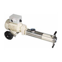
Allweiler AEB1E Operating Instructions Manual (60 pages)
Progressive Cavity Pump
Brand:
Allweiler
| Category:
Water Pump
| Size: 2 MB
Table of Contents
Table of Contents
2
About this Document
5
Target Groups
5
Other Applicable Documents
5
Target Groups and Their Duties
5
Other Applicable Documents and Their Purpose
5
Warnings and Symbols
6
Warnings and Consequences of Disregarding Them
6
Symbols and Their Meaning
6
Safety
7
Intended Use
7
General Safety Instructions
7
Product Safety
7
Operator's Obligations
7
Obligations of Personnel
8
Specific Hazards
8
Explosion-Hazard Area
8
Hazardous Pumped Liquids
8
Layout and Function
9
Labels
9
Nameplate
9
Pump Type Code
9
Fig
9
Protection Mark)
9
Layout
10
Base Version
10
RG Version (Open-Feed Version with Internal Gearbox Mounting)
11
Function
11
Shaft Seals
11
Packing Gland
11
Mechanical Seals
11
Bearings and Lubrication
11
With Internal Gearbox Mounting)
11
Auxiliary Systems
12
Sealing System
12
Heating and Cooling System (Optional)
12
Types of Setup
12
Installation
12
Transport, Storage and Disposal
13
Transport
13
Unpacking and Inspection on Delivery
13
Lifting
13
Treatment for Storage
13
Illustrated)
13
Close-Coupled Pump (as Illustrated)
13
Storage
14
Removing Preservative
14
Disposal
14
Setup and Connection
15
Preparing the Setup
15
Determining the Setup Type
15
Checking the Ambient Conditions
15
Preparing the Installation Site
15
Preparing the Foundation and Surface
15
Removing Preservative
15
Installing the Heat Insulation (Optional)
15
Installation on a Foundation
16
Placing the Pump Unit on the Foundation
16
Fastening the Pump Unit
16
Installation with Foundation
16
Installing the Motor
17
Close-Coupled Pump with Stub Shaft
17
Pump with Coupling
17
Pump with Belt Drive
17
Planning the Pipes
17
Specifying Supports and Flange Connections
17
Specifying Nominal Diameters
18
Specifying Pipe Lengths
18
Optimizing Changes in Cross-Section and Direction
18
Discharging Leaks
18
Providing Safety and Control Devices (Recommended)
18
Straight Pipe Lengths Upstream and Downstream of the Pump (Recommended)
18
Connecting the Pipes
19
Keeping the Piping Clean
19
Installing Auxiliary Piping
19
Installing the Suction Pipe
19
Installing the Pressure Line
19
Inspection for Stress-Free Pipe Connections
19
Inspecting the Support Foot on the Discharge Casing (504) for Distortion
19
Electrical Connection
19
Aligning the Coupling Precisely
20
Checking the Alignment of the Coupling
20
Checking for Lateral and Vertical Misalignment
20
Checking for Angular Displacement
20
Aligning the Motor
21
Installing the Safety Guarding
21
Coupling Guard
21
Belt Guard
21
Operation
22
Preparing Initial Start-Up
22
Identifying the Pump Type
22
Removing Preservative
22
Preparing Auxiliary Systems (if Available)
22
Filling Pump
22
Turning the Pump
22
Checking the Sense of Rotation
23
Start-Up
23
Switching on
23
Switching off
23
Shutting down the Pump
24
Draining the Pump
24
Start-Up Following a Shutdown Period
24
Operating the Stand-By Pump
24
Measures to be Taken if the Pump Is Shut down
24
Measures Depending on the Behavior of the Pumped Liquid
24
Maintenance
25
Inspections
25
Antifriction Bearings Lubricated with
26
Grease
26
Spur Gear with Oil Lubrication (RG Design)
26
Joints with Oil Lubrication
26
Packing Gland
26
Mechanical Seals
26
Drive Seal (RG Design)
26
V-Belt Drive
27
Motor
27
7.2.10 Cleaning the Pump
27
Dismounting
27
Returning the Pump to the Manufac
28
Dismounting
28
Turer
28
Residual Liquid in the Pump
28
Measures for Return
28
Installing
29
Ordering Spare Parts
29
Troubleshooting
30
Pump Malfunctions
30
Malfunction/Number Assignment
30
Pump Troubleshooting List
32
Appendix
33
Part Numbers and Designations
33
Sectional Drawings
33
Numbers
37
Drawings
38
Sectional Drawings
39
AE, Design ID and AEB, Design IE
39
AE, Design ZD and AEB, Design ZE
40
AE, Dosing Pump Design
41
AE, Design RG
42
Universal Joint Shaft)
42
AE, Design RG (Detailed Views: Mixing Screw and Bearings of Specific Sizes)
43
Packing Gland with Flushing Ring (P02)
44
Packing Gland with Internal Lantern Ring (P03)
44
Packing Gland with External Lantern Ring (P04)
44
Mechanical Seal, Single-Action (G0K and G0N)
44
Tab
44
Mechanical Seal, Single-Action with Throttle Ring (G0S and G0T)
45
Mechanical Seal, Single-Action with Quenching (G0Q)
45
Mechanical Seal, Double-Action (G0D)
45
Stator Versions
46
Technical Specifications
47
Ambient Conditions
47
Preservatives
47
Cleaning Agents
47
Parameters for Auxiliary Systems
47
Tab
47
Lubricants
48
Lubrication Quantities (RG Design)
48
Tab. 23
48
Mechanical Seal
48
With Quenching
48
Heating Medium
48
Tightening Torques
49
Sound Pressure Level
49
Pumps
49
Tab
50
Groups
52
Tab
52
Quantity
53
Pump Group
53
AE1F and AEB1F
53
AE1L and AEB1L
53
AE1E and AEB1E
53
Total Volume and Residual Liquid Quantity AED1E
53
Total Volume and Residual Liquid Quantity AE2E and AEB2E
54
AE1N and AEB1N
54
AE2N and AEB2N
54
Total Volume and Residual Liquid Quantity AEB3N
54
Total Volume and Residual Liquid Quantity AE4N
54
Total Volume and Residual Liquid Quantity AED2N and AEDB2N
54
Total Volume and Residual Liquid Quantity AE1+1H
55
Total Volume and Residual Liquid Quantity AE2H
55
Total Volume and Residual Liquid Quantity AE2+2H
55
Total Volume and Residual Liquid Quantity AE4H
55
Total Volume and Residual Liquid Quantity AE2+2V
55
Total Volume and Residual Liquid Quantity AE4+4V
55
Declaration of Harmlessness
56
Declaration of Conformity According to EC Fig. 28 Machine Directive
57
Declaration of Conformity According to EC Machine Directive
57
Advertisement
Allweiler AEB1E Operating And Maintenance Instructions Manual (44 pages)
Progressing cavity pump
Brand:
Allweiler
| Category:
Water Pump
| Size: 0 MB
Table of Contents
Table of Contents
3
About These Instructions
7
Who Should Read These Instructions
7
Related Documents
7
Warning Notices and Symbols
7
Technical Terms
8
Safety Notices
8
Keep Information Accessible
8
Inspection
8
Warranty
8
Safety
9
Dangers of Failure to Observe Safety Notices
9
Proper Use
9
2.3 Avoiding Common Mistakes
9
Avoiding Common Mistakes (Examples)
9
General Safety Notices
9
Product Safety
9
Operator's Responsibilities
9
Personnel Responsibilities
10
Safety Precautions
10
Authorized Operating Personnel
10
Safety Measures During Normal Operation
10
Safety at the Place of Installation
10
Maintenance and Repair
10
Removal of Malfunctions
10
Unauthorized Conversion and Production of Spare Parts
11
Impermissible Operating Methods
11
Protective Clothing
11
Residual Risks
11
Danger Points
12
Hazards When Working with the System
12
Dangers of Leaks
12
Dangers of Electrical Energy
12
Hazards Caused by Dust
12
Dangers of Moving Parts
12
Danger of Hot or Cold Parts
12
Operating in Potentially Explosive Atmospheres
12
Danger of Pumped Liquid
12
Design and Function
13
Application and Area of Usage
13
Labeling
13
Nameplate
13
ATEX Nameplate
13
Pump Model Label
13
Performance Data
13
Design
13
Structural Design
13
Bearing and Lubrication
13
Dimensions/ Branch Positions/Flanges
14
Noise Level
14
Non-Ionizing Radiation
14
Operation
14
Pump Unit Design
14
Drive
14
Transport, Storage, and Disposal
15
Packaging
15
Transportation
15
Preserving Progressing Cavity Pumps and Placing Them into Storage
15
Preserving
15
Storage
15
Disposal
16
Installation and Connection
17
Setting up the Pump
17
Space Requirement for Maintenance and Repair
17
Laying the Pipes
17
Nominal Widths
17
Supports and Connection Lines
17
Cleaning the Connections Lines before Installation
17
Safety and Inspection Equipment
17
Pressure and Vacuum Gauges
17
Safety Device in the Pressure Line
18
Electrical Connections
18
Operation
19
Preparing for Initial Start-Up
19
Filling the Pump with Liquid
19
Pump Rotation Difficulties
19
Checking the Direction of Rotation
19
Bringing the Pump into Operation
19
Starting
19
Drive
19
Checking Pump Capacity
20
Dry-Running Protection
20
Series AEB1E, AEB2E, AEB2N
20
Taking the Pump out of
20
Operation
20
Stoppage
20
Downtime
20
Special Applications of the Pump14
20
Maintenance Cycles and Intervals
21
Preventive Maintenance
22
Maintenance
22
General Monitoring
22
Universal Joints
22
Shaft Seal
22
Mechanical Seal
22
Drive Motors and (Variable) Gear16
22
Maintenance
23
Disassembly and Assembly
23
Instructions
23
Disassembling the Progressing
23
Cavity Pump
23
Removing the Stator
23
Removing the Rotor and Rotor- Side Joint
24
Fig. 4 Removing the Joint Clamp
24
Fig. 5 Removing the Joint Sleeve
24
Fig. 6 Removing the Bushes for Joint Bolt
24
Removing the Universal Joint Shaft and the Drive-Side Joint
25
Removing the Shaft Seal and Stub Shaft
25
Removing the Mechanical Seal, Single-Acting
25
Assembling the Progressing Cavity Pump
25
Installing the Shaft Seal and Stub Shaft
25
Installing the Mechanical Seal, General
25
Installing the Mechanical Seal, Single-Acting
26
Installing the Stub Shaft with Shaft Seal
26
Installing the Rotor and Rotor-Side Joint
27
Fig. 7 Clamp Sets in Inner Collar
27
Fig. 8 Pressing in the Joint Bush
27
Fig. 9 Securing the Joint Sleeve
27
Tightening with Clamping Tool Pok
28
It II
28
Fig. 10 Apply Pressure to the Joint Clamp Strap on the Joint Clamp Seal
28
Fig. 11 Tightening the Joint Clamps
28
Fig. 12 Canting and Shearing off the Joint Clamp
28
Installing the Universal Joint Shaft and the Drive-Side Joint
29
Installing the Stator
29
Spare Parts
30
Index of Spare Parts and Recommended Spare/Reserve Parts
31
Sectional Drawings for ME Construction Type
33
Fig. 13 Sectional Drawings for ME Construction Type
33
Sectional Drawing of SE Construction Type on Leveling Feet
34
Fig. 14 Sectional Drawing of SE Construction Type on Leveling Feet
34
Construction Type
35
Fig. 15 Sectional Drawings for SE Construction Type
35
Sectional Drawings for VE Measures for Longer Periods of Construction Type
36
Fig. 16 Sectional Drawings for VE Construction Type
36
Causes and Removal of Operational Faults
37
Clearance Certificate
39
Fig. 16 Clearance Certificate
39
Machinery Directive
40
EG-Konformitätserklärung
41
Fig. 17 EC Declaration of Conformity
41
Advertisement
Related Products
Allweiler AEB.E Series
Allweiler AEB.F Series
Allweiler AEB.N Series
Allweiler AEB.L Series
Allweiler AEB1F
Allweiler AEB1L
Allweiler AEB2E
Allweiler AEB1N
Allweiler AEB2N
Allweiler AEB3N
Allweiler Categories
Water Pump
More Allweiler Manuals
Login
Sign In
OR
Sign in with Facebook
Sign in with Google
Upload manual
Upload from disk
Upload from URL