Table of Contents
Advertisement
Quick Links
Screw Pump
Original Operating Manual
Version
BA-2021.06 en-US
147-276/H
ID-No.
550 851
ALLFUEL Series
ALLWEILER GmbH
Postfach 1140
Allweilerstraße 1
78301 Radolfzell
Germany
Phone: +49 (0) 7732-86-0
Fax: +49 (0) 7732-86-436
E-mail: service@allweiler.de
Internet: http://www.allweiler.com
We reserve the right to make technical changes.
Read carefully before use.
Retain for future use.
Advertisement
Table of Contents
Troubleshooting

Related Manuals for Allweiler CIRCOR ALLFUEL Series


Summary of Contents for Allweiler CIRCOR ALLFUEL Series
- Page 1 Screw Pump Original Operating Manual ALLFUEL Series Version BA-2021.06 en-US ALLWEILER GmbH 147-276/H Postfach 1140 ID-No. 550 851 Allweilerstraße 1 78301 Radolfzell Germany Phone: +49 (0) 7732-86-0 Fax: +49 (0) 7732-86-436 E-mail: service@allweiler.de Internet: http://www.allweiler.com We reserve the right to make technical changes.
-
Page 2: Table Of Contents
Table of contents Table of contents About this document ....... Installing the motor . - Page 3 Table of contents 7.3.4 Installing ........27 7.3.5 Adjusting the pressure relief valve .
- Page 4 Table of contents List of figures List of tables Fig. 1 Nameplate (example) ......10 Tab. 1 Target groups and their duties .
-
Page 5: About This Document
About this document About this document This manual: • Is part of the pump • Applies to the pump series mentioned above • Describes safe and appropriate operation during all oper- ating phases Target groups Target group Duty Operating company Keep this manual available at the site of operation of the equipment, including for later use. -
Page 6: Warnings And Symbols
About this document Warnings and symbols Warning Risk level Consequences of disregarding the warning Immediate acute risk Death, serious bodily harm DANGER Potential acute risk Death, serious bodily harm Potentially hazardous situation Minor bodily harm CAUTION Potentially hazardous situation Material damage NOTE Tab. -
Page 7: Safety
Safety Safety The manufacturer does not accept any liability for damages General safety instructions caused by disregarding the entire documentation. Observe the following regulations before carrying out any work. Intended use 2.2.1 Product safety • Only use the pump to pump the agreed pumped liquids The pump has been constructed according to the latest tech- (→... -
Page 8: Obligations Of Personnel
(EN ISO 5199 also applicable for drives of screw • Have all electrical work carried out by qualified electricians pumps). only. • When using combustion engines, consult Allweiler. • For pumps with stub shaft, connect drive system and pump directly with stub shaft. ALLFUEL Series BA-2021.06 en-US... -
Page 9: Hazardous And Spraying (Pumped) Liquids
Safety 2.3.3 Hazardous and spraying (pumped) liquids (Pumped) liquids can be toxic and hot and can spray out. There is a risk of burns and skin rashes on contact. • Follow the safety regulations for handling hazardous sub- stances when handling hazardous (e.g. hot, flammable, poisonous or potentially harmful) pumped liquids. -
Page 10: Layout And Function
Layout and function Layout and function Label 3.1.1 Nameplate A100000000000201 Fig. 3 Digital nameplate, variant with optional RFID Fig. 1 Nameplate (example) transmitter (example) Pump type Identification number Year of manufacture RFID transponder (HF) Discharge pressure QR code Suction head Power consumption 3.1.3 ATEX plate... -
Page 11: Pump Type Code
Layout and function 3.1.4 Pump type code Posi- tion Meaning Series AFI - T 10 R 38 D 19US W226 E V F C B - NO 80 Version Insert unit Single unit with filter Twin unit with filter Omitted for individual units without filter (AFI) Size Theoretical flow rate Q in l/min at 1450 rpm and 46°... -
Page 12: Layout
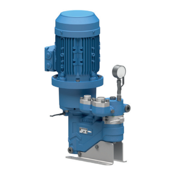
Layout and function Layout Fig. 6 Pump layout Drive screw Shaft seal Motor Idler rotor Bearing 10 Limit for heat insulation Casing insert Coupling Pump casing Pump carrier ALLFUEL Series BA-2021.06 en-US 550 851 – 147-276/H... - Page 13 Layout and function Fig. 7 Layout of twin unit with filter Ball valve Coupling Casing insert Filter Bearing 10 Drive screw Motor Shaft seal 11 Idler rotor Pump carrier Pump casing 550 851 – 147-276/H BA-2021.06 en-US ALLFUEL Series...
-
Page 14: Shaft Seals
Layout and function Shaft seals Hydraulic diagram For twin unit with filter (AFI-T) only. 3.3.1 Mechanical seals Mechanical seals have functional leakage. • Mechanical seal, standard version – Uncooled, maintenance-free unbalanced mechanical seal construction Bearings and lubrication • External antifriction bearing lubricated with grease accord- ing to DIN 625 –... -
Page 15: Transport, Storage And Disposal
Transport, storage and disposal Transport, storage and disposal Transport Weight specifications (→ order data sheet). 4.1.1 Unpacking and inspection on delivery 1. Unpack the pump/unit on delivery and inspect it for trans- port damage. 2. Report any transport damage to the manufacturer immedi- ately. -
Page 16: Treatment For Storage
Transport, storage and disposal Treatment for storage Removing the preservative The pump has not been treated for storage at the factory. Only necessary for pumps treated for storage. Treatment is not necessary for non-rusting materials. Contact the manufacturer for recommendations regarding preservatives. -
Page 17: Setup And Connection
Setup and connection Setup and connection For pumps in explosion-hazard areas (→ ATEX additional 5.1.5 Installing the heat insulation (optional) instructions). Only necessary to maintain the temperature of the pumped liquid. NOTE NOTE Material damage due to distortion or passage of electrical current in the bearing! Material damage on the bearing or shaft seal due to over- Do not make any structural modifications to the pump unit... -
Page 18: Installing The Motor
Setup and connection Installing the motor 5.4.3 Specifying pipe lengths 5.3.1 Installing the motor on pumps in flange versions Only necessary if the pump unit is assembled on site. NOTE Material damage caused by knocks and bumps! Keep the coupling halves properly aligned when slipping them on. -
Page 19: Avoiding Excessive Pressure
Setup and connection 5.4.6 Avoiding excessive pressure 5.4.7 Providing safety and control devices (recommended) WARNING Avoid impurities Not necessary with filter units. Risk of injury due to excessive pressure! If no pressure relief valve is present: Provide an appropri- ate safety valve in the pressure line. 1. -
Page 20: Connecting The Pipes
Setup and connection Connecting the pipes Electrical connection 5.5.1 Keeping the pipes clean DANGER NOTE Risk of death due to electric shock! Have all electrical work carried out by qualified electricians Material damage due to impurities in the pump! only. Make sure no impurities can enter the pump. -
Page 21: Operation
Operation Operation For pumps in explosion-hazard areas (→ ATEX additional Putting the pump into service instructions). for the first time Operation of twin units: Using the changeover ball valve 6.1.1 Removing the preservative (401), one of the pumps can be switched to Service (depressurized): Only necessary for pumps treated for storage. -
Page 22: Switching On
Operation Operation 6.1.5 Switching on Pump set up and connected properly 6.2.1 Switching on Motor set up and connected properly Pump initially put into service properly All connections stress-free and sealed Pumps filled and bled All safety equipment installed and tested for functionality Pump prepared, filled and bled properly Sufficient filling level in the container NOTE... -
Page 23: Switching Off
Operation 6.2.4 Switching off 6.3.2 Draining the pump Switch off the motor. 1. Drain the pump using the suction and pressure lines and the built-in sealing and air release plugs. 2. If the adjusting screw (333) of the pressure relief valve has Shutting down the pump to be removed for draining: –... - Page 24 Operation 9. After cleaning, put the filter (480) back into the filter housing so that the magnet on the filter base rests against the drain plug (217). 10. Fill the pump casing with liquid (1). 11. Screw on the housing cover (22). The O-rings (122, 126) must lie in the groove and must be undamaged.
-
Page 25: Maintenance
Maintenance Maintenance For pumps in explosion-hazard areas (→ ATEX additional Maintenance instructions). Service life of the antifriction bearings for operation within Trained service technicians are available for fitting and the permissible operating range: > 2 years repair work. Present a pumped liquid certificate (DIN Intermittent operation, high temperatures and aggressive safety data sheet or safety certificate) when requesting ambient and process conditions reduce the service life of... -
Page 26: Repairs
Maintenance Repairs 7.3.2 Removing the pump from the unit Only operate the twin unit with one pump for brief periods. WARNING On twin units, you may have to switch on the stand-by Risk of injury due to heavy components! pump using the the pump controller. Pay attention to the component weight. -
Page 27: Installing
Maintenance Ordering spare parts 7.3.4 Installing Install the components concentrically, without canting, in For trouble-free replacement in the event of faults, we rec- accordance with the markings made. ommend keeping entire spare pumps or insert units avail- able on site. Parts which can be replaced can be found in the parts list NOTE (→... -
Page 28: Troubleshooting
Troubleshooting Troubleshooting Pump malfunctions If malfunctions occur which are not specified in the following table or cannot be traced back to the specified causes, please consult the manufacturer. Possible malfunctions are identified by a number in the follow- ing table. This number identifies the respective cause and rem- edy in the troubleshooting list. - Page 29 Troubleshooting Malfunction number Cause Remedy – – – – Excess play between: Repair or replace any worn parts. • Spindles • Spindles and housing – – – – Shaft seal leaky Replace the shaft seal. – – – – – –...
-
Page 30: Pressure Relief Valve Malfunctions
Troubleshooting Malfunction number Cause Remedy – – – – Pump distorted Check the pipe connections and pump attachment. – – – – – – – Coupling elements worn Replace the coupling elements. – – – – Motor running on 2 phases Check the fuse and replace it if necessary. -
Page 31: Appendix
Appendix Appendix Sectional drawings Part no. Designation O-ring 9.1.1 Auxiliary connections O-ring Abbreviation Connection O-ring Drain O-ring Bleeding the pump Seal ring Bleeding the filter Seal ring Heating cartridge Seal ring M1, M2, M3 Pressure gauge, temperature gauge Tab. 13 Abbreviations of the connection designations Seal ring 1) 2) -
Page 32: Sectional Drawings
Appendix Part no. Designation Part no. Designation Screw plug Heater Screw plug Heater Cover plate Screw plug Screw plug Changeover ball valve Hexagon nut Welding neck flange Hexagon nut Welding neck flange Hexagon nut Pump carrier Screw plug Mounting foot Screw plug Oil sump Disc... - Page 33 Appendix Fig. 14 Pump 550 851 – 147-276/H BA-2021.06 en-US ALLFUEL Series...
- Page 34 Appendix Fig. 15 Twin unit with filter 1/2 Check valve Bearing and gasket ALLFUEL Series BA-2021.06 en-US 550 851 – 147-276/H...
- Page 35 Appendix Fig. 16 Twin unit with filter 2/2 Vent 550 851 – 147-276/H BA-2021.06 en-US ALLFUEL Series...
- Page 36 Appendix Fig. 19 Changeover ball valve Fig. 17 Insert unit Fig. 20 Pressure relief valve Fig. 18 Pressure gauge ALLFUEL Series BA-2021.06 en-US 550 851 – 147-276/H...
-
Page 37: Technical Specifications
Appendix Technical specifications 9.2.4 Cleaning agents More technical specifications (→ order data sheet). Application area Cleaning agents Other Benzine, wax solvents, 9.2.1 Ambient conditions diesel, paraffin, alkaline cleaners Operation under any other ambient conditions should be agreed with the manufacturer. Tab. -
Page 38: Declaration Of Harmlessness
Every commercial company is obligated to comply with the legal regulations on work www.allweiler.de/ safety, set forth for example in Germany in the Workplace Ordinance (ArbStättV), en/sales-service/ downloads the Accident Prevention Regulations (UVV), the Hazardous Substances Ordinance (GefStoffV) and the applicable environmental regulations. -
Page 39: Declaration Of Conformity According To Ec Machine Directive
The original declaration is delivered with the respective pump. EC declaration of conformity according to Machine Directive, Appendix II A ALLWEILER GmbH, Postfach 1140, 78301 Radolfzell, Germany; Tel. +49 (0)7732 86-0, Fax. +49 (0)7732 86-436 hereby declare that the pump unit/pump: Designation ALLFUEL Equipment no. - Page 40 Appendix ALLFUEL Series BA-2021.06 en-US 550 851 – 147-276/H...
Need help?
Do you have a question about the CIRCOR ALLFUEL Series and is the answer not in the manual?
Questions and answers