Advertisement
Quick Links
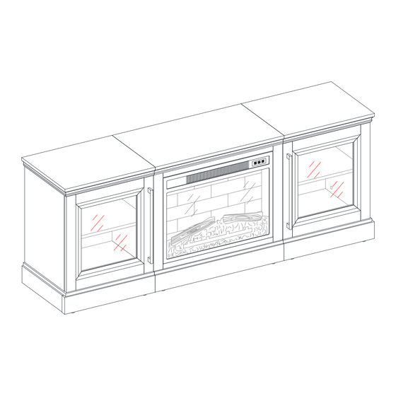
75" Media Fireplace Console
If you have any questions regarding assembly or if parts are missing, DO NOT return this item to the
store where it was purchased. Please call our customer service number and have your instructions
and parts list ready to provide the model name, part name or factory number:
Pacific Standard Time: 8:30 a.m. - 4:30 p.m., Monday - Friday
Or visit our web site 24 hours a day, 7 days a week for product assistance at
THIS INSTRUCTION BOOKLET CONTAINS IMPORTANT SAFETY INFORMATION.
Stock # WMFP65EC-27BA
# WMFP65EC-27WB
ADULT ASSEMBLY REQUIRED
www.whalenstyle.com
Or e-mail your request to parts@whalenfurniture.com
PLEASE READ AND KEEP FOR FUTURE REFERENCE.
Date 2023-06-27
866-942-5362
Rev. 0001-A
LOT NUMBER:
DATE PURCHASED:
/
/
Advertisement

Related Manuals for Whalen WMFP65EC-27BA


Summary of Contents for Whalen WMFP65EC-27BA
- Page 1 LOT NUMBER: DATE PURCHASED: 75” Media Fireplace Console Stock # WMFP65EC-27BA # WMFP65EC-27WB ADULT ASSEMBLY REQUIRED If you have any questions regarding assembly or if parts are missing, DO NOT return this item to the store where it was purchased. Please call our customer service number and have your instructions...
- Page 2 G E N E R A L I N F O R M A T I O N , T I P S A N D T R I C K S 1. Please read the Assembly Instructions prior to assembling this product. 2.
- Page 3 IMPORTANT Before you begin: Open, identify and count all parts prior to assembly. Lay out parts on a flat and non- abrasive surface. You will need the parts identified on page 4 and 5 of this instruction manuals. NOTE: IT IS VERY IMPORTANT TO USE GLUE WITH DOWELS. EXCESS GLUE CAN BE WIPED OFF WITH DAMP CLOTH.
- Page 4 Parts and Hardware List Please read completely through the instructions and verify that all listed parts and hardware are present before beginning assembly. A- Middle Top Panel ( B- Left Partition Panel ( Qty. 1 Qty. 1 C- Right Partition Panel ( D- Middle Crossbar ( Qty.
- Page 5 Parts and Hardware List Please read completely through the instructions and verify that all listed parts and hardware are present before beginning assembly. M- Left Top Panel ( N- Side Panel ( Qty. 1 Qty. 2 O- Left Bottom Panel ( P- Left Front Skirting ( Qty.
- Page 6 Parts and Hardware List Please read completely through the instructions and verify that all listed parts and hardware are present before beginning assembly. (1) Cam Lock (2) Cam Bolt (3) M8 x 30 mm Wood Dowel (Qty. 52+2 extra) (Qty. 52+2 extra) (Qty.
- Page 7 Assembly Instructions ② x 14 NOTE: Please do not fully tighten all bolts until you finish assembling all parts. Once assembled, go back and fully tighten all bolts. This will make it easier during assembly of unit. 1. Unpack the unit and confirm that you have all the hardware and required parts. Assemble the unit on a carpeted floor or the empty carton to avoid any scratch.
- Page 8 Assembly Instructions ③ x 18 3. Glue the 30 mm Wood Dowels (3) into the designated holes on the Firebox Long Support (E), Middle Front Skirting (H), Middle Rear Skirting (I), Bottom Supports (J and K) and Firebox Short Supports (L) as shown.
- Page 9 Assembly Instructions ④ x 4 4. Align and attach the Firebox Short Supports (L) to the Middle Bottom Panel (G) with four 28 mm Screws (4).
- Page 10 Assembly Instructions ④ x 3 5. Align and attach the Firebox Long Support (E) to the Middle Bottom Panel (G) with three 28 mm Screws (4).
- Page 11 Assembly Instructions ① x 2 6. Align and attach the Middle Rear Skirting (I) between the Bottom Supports (J and K) with two Cam Locks (1). (Refer to page 3 on Cam Lock system operation supplement).
- Page 12 Assembly Instructions ① x 2 7. Align and attach the Middle Front Skirting (H) to the Bottom Supports (J and K) by engaging two Cam Locks (1).
- Page 13 Assembly Instructions ① x 10 8. Orient and attach the assembled Middle Base (H, I, J and K) to the Middle Bottom Panel (G) by engaging ten Cam Locks (1).
- Page 14 Assembly Instructions ② x 6 9. Securely screw six Cam Bolts (2) into the designated small holes on the Middle Bottom Panel (G) and Bottom Supports (J and K), using a Phillips screwdriver.
- Page 15 Assembly Instructions ② x 8 10. Securely screw the Cam Bolts (2) into the designated small holes on the Middle Top Panel (A) and Middle Trims (F), using a Phillips screwdriver.
- Page 16 Assembly Instructions ③ x 14 11. Glue the 30 mm Wood Dowels (3) into the designated holes on both Partition Panels (B and C) and Middle Crossbar (D) as shown.
- Page 17 Assembly Instructions ⑤ x 3 12. Fasten the Middle Crossbar (D) to the Middle Top Panel (A) with three 38 mm Screws (5).
- Page 18 Assembly Instructions ① x 4 13. Orient and attach the Middle Trim (F) to each Partition Panel (B and C) by engaging two Cam Locks (1).
- Page 19 Assembly Instructions ① x 4 14. Using the wood dowels as a guide, firmly press the assembled Partition Panels (B and C) to the Middle Bottom Panel (G) and fasten them in place by engaging four Cam Locks (1).
- Page 20 Assembly Instructions ① x 4 15. Properly position the Middle Top Panel (A) so that the cam bolts enter the holes in top edge of both Partition Panels (B and C) and fasten them into place by engaging four Cam Locks (1).
- Page 21 Assembly Instructions ⑥ x 4 ⑩ x 2 16. Using the pilot holes as a guide, attach two Door Stoppers (10) to the Partition Panels (B and C) respectively with four 12 mm Pan Head Screws (6).
- Page 22 Assembly Instructions ② x 10 17. Securely screw the Cam Bolts (2) into the designated small holes on the Left Top Panel (M), Left Bottom Panel (O), Left Front Skirting (P) and Left Side Skirting (R), using a Phillips screwdriver.
- Page 23 Assembly Instructions ⑧ x 3 18. Align and attach the Plastic Connectors (11) to the Left Bottom Panel (O) and Left Front Skirting (P) with three 12 mm Bolts (8).
- Page 24 Assembly Instructions ③ x 15 19. Glue the 30 mm Wood Dowels (3) into the designated holes on the Left Top Panel (M), the Side Panel (N), Left Skirtings (P, Q and R) as shown.
- Page 25 Assembly Instructions ① x 1 20. Orient and attach the Left Rear Skirting (Q) to the Left Side Skirting (R) by engaging one Cam Lock (1).
- Page 26 Assembly Instructions ① x 1 21. Attach the Left Front Skirting (P) to the Left Side Skirting (R) by engaging one Cam Lock (1).
- Page 27 Assembly Instructions ① x 6 22. Align and attach the Left Skirting Boards to the Left Bottom Panel (O) by engaging six Cam Locks (1).
- Page 28 Assembly Instructions ② x 2 23. Securely screw two Cam Bolts (2) into the designated small holes on the top of the Left Bottom Panel (O), using a Phillips screwdriver.
- Page 29 Assembly Instructions ① x 2 24. Orient and attach one Side Panel (N) to the Left Bottom Panel (O) by engaging two Cam Locks (1).
- Page 30 Assembly Instructions ① x 2 25. Align and attach the Left Top Panel (M) to the Side Panel (N) by engaging two Cam Locks (1).
- Page 31 Assembly Instructions ② x 10 26. Securely screw the Cam Bolts (2) into the designated small holes on the Right Top Panel (S), Right Bottom Panel (T), Right Front Skirting (U) and Right Side Skirting (W), using a Phillips screwdriver.
- Page 32 Assembly Instructions ⑧ x 3 27. Align and attach the Plastic Connectors (11) to the Right Bottom Panel (T) and Right Front Skirting (U) with three 12 mm Bolts (8).
- Page 33 Assembly Instructions ③ x 15 28. Glue the 30 mm Wood Dowels (3) into the designated holes on the Right Top Panel (S), the Side Panel (N), Right Skirtings (U, V and W) as shown.
- Page 34 Assembly Instructions ① x 1 29. Orient and attach the Right Rear Skirting (V) to the Right Side Skirting (W) by engaging one Cam Lock (1).
- Page 35 Assembly Instructions ① x 1 30. Attach the Right Front Skirting (U) to the Right Side Skirting (W) by engaging one Cam Lock (1).
- Page 36 Assembly Instructions ① x 6 31. Align and attach the Right Skirting Boards to the Right Bottom Panel (T) by engaging six Cam Locks (1).
- Page 37 Assembly Instructions ② x 2 32. Securely screw two Cam Bolts (2) into the designated small holes on the top of the Right Bottom Panel (T), using a Phillips screwdriver.
- Page 38 Assembly Instructions ① x 2 33. Attach the other Side Panel (N) to the Right Bottom Panel (T) by engaging two Cam Locks (1).
- Page 39 Assembly Instructions ① x 2 34. Align and attach the Right Top Panel (S) to the Side Panel (N) by engaging two Cam Locks (1).
- Page 40 Assembly Instructions ① x 2 ⑧ x 6 35. Line up the assembled units on a level and protected surface and combine them together, using the inserted wood dowels as a guide. 36. Insert six 12 mm Bolts (8) through the Plastic Connectors (11) and screw into the Bottom Supports (J and K).
- Page 41 Assembly Instructions ⑨ x 4 38. Proceed to insert four 65 mm Bolts (9) through the mounting holes on the subframe of Middle Top Panel (A) and screw into the Side Top Panels (M and S).
- Page 42 Assembly Instructions ⑦ x 32 39. Ask for assistance to flip around the previous assembly at its front edges. 40. Now, go back and securely tighten all the Cam Locks and Screws. Make sure that all the parts are tight and there are no gaps between the parts.
- Page 43 Assembly Instructions 42. Attach one Handle (A1) to the front side of each Door (Y) with two Handle Bolts (14).
- Page 44 Assembly Instructions Vertical Depth Horizontal Adjustment Adjustment Adjustment 43. Ask for assistance to lift the assembly unit upright and position it near the final location. 44. Pick up one Door (Y) and attach the extended Hinge Arms to the Hinge Bases installed on one Side Panel (N).
- Page 45 Assembly Instructions 47. Open the doors and insert four Shelf Supports (12) into the holes at the desired height inside each side compartment. Make sure you place the four shelf supports at the same level to make the shelf level. 48.
- Page 46 Assembly Instructions 49. Plug the Cam Lock Covers (13) onto the visible cam locks to conceal the cams.
- Page 47 Assembly Instructions 50. Unpack the fireplace insert from the inner box and follow the instructions to install the Top Trim and Side Trims to the fireplace insert. 51. Lift the fireplace insert carefully into the back of the assembled mantel and center it in the opening. drag the insert across the Middle Bottom Panel (G) as it may scratch the unit.
- Page 48 Assembly Instructions Tools required (not provided): Phillips screwdriver, stud finder, tape measure, pencil, power drill and 1/8’’ drill bit. 53. Ask for assistance to position the assembled fireplace at the desired location against a wall. If necessary, adjust the pre-attached Floor Levelers at the bottom of the Front Skirtings to correct the tilting and level the doors.
-
Page 49: Care And Maintenance
Care and Maintenance Use a soft, clean cloth that will not scratch the surface when dusting. Use of furniture polish is not necessary. Should you choose to use polish, test first in an inconspicuous area. Using solvents of any kind on your furniture may damage your furniture’s finish. ... -
Page 50: Quality Guarantee
Should this product be defective in workmanship or materials or fail under normal use, we will repair or replace it for up to one (1) year from date of purchase. Every Whalen Furniture product is designed to meet your highest expectations. We guarantee that you will immediately see the value of our fine furniture. - Page 51 NÚMERO de LOTE:__________ FECHA de COMPRA: Consola para medios con chimenea de 75” Serie # WMFP65EC-27BA # WMFP65EC-27WB ENSAMBLE REQUERIDO POR ADULTO Si tienen alguna pregunta acerca del ensamble o si alguna parte está faltante, no retorne esté producto a la tienda donde lo compro.
- Page 52 I N F O R M A C I Ó N G E N E R A L , R E C O M E N D A C I O N E S Y T R U C O S 1.
- Page 53 Importante Antes de comenzar: Abra, identifique y cuente todas las partes antes del ensamble. Coloque las piezas sobre una superficie plana y no abrasiva. Tendrá las partes identificadas en la página 4 y 5 de este manual de instrucciones. NOTA: ES MUY IMPORTANTE EL USO DE GOMA CON LAS CLAVIJAS DE MADERA.
- Page 54 Lista de partes y material de ferretería Por favor lea completamente las instrucciones y verifique que estén todas las partes y partes de ferretería antes de iniciar el ensamblado. A- Panel medio superior ( B- Panel divisor izquierdo ( Cant. 1 Cant.
- Page 55 Lista de partes y material de ferretería Por favor lea completamente las instrucciones y verifique que estén todas las partes y partes de ferretería antes de iniciar el ensamblado. M- Panel izquierdo superior (Cant. 1) N- Panel lateral (Cant. 2) O- Panel izquierdo inferior (Cant.
- Page 56 Lista de partes y material de ferretería Por favor lea completamente las instrucciones y verifique que estén todas las partes y partes de ferretería antes de iniciar el ensamblado. (1) Tuerca de fijación (2) Perno de fijación (3) Clavija de madera de M8 x 30 mm (Cant.
- Page 57 Instructivo de ensamble ② x 14 NOTE: Por favor no apriete completamente todos los pernos, hasta que termine con el ensamble de las partes. Una vez ensamblado, volver y apretar todos los pernos. Esto hará el ensamble de la unidad más fácil. 1.
- Page 58 Instructivo de ensamble ③ x 18 3. Pegar las clavijas de madera de 30 mm (3) en los agujeros designados en el soporte largo de la chimenea (E), en el soporte medio frontal (H), en el soporte medio posterior (I), en los soportes inferiores (J y K) y en los soportes cortos de la chimenea (L) como se muestra.
- Page 59 Instructivo de ensamble ④ x 4 4. Alinear y adjuntar los soportes cortos de la chimenea (L) al panel medio inferior (G) con 4 pernos de 28 mm (4).
- Page 60 Instructivo de ensamble ④ x 3 5. Alinear y adjuntar los soportes largos de la chimenea (E) al panel medio inferior (G) con 3 pernos de 28 mm (4).
- Page 61 Instructivo de ensamble ① x 2 6. Alinear y adjuntar el soporte medio posterior (I) entre los soportes inferiores (J y K) con 2 pernos de fijación (1). (Consulte la página 3 del sistema de tuerca de fijación).
- Page 62 Instructivo de ensamble ① x 2 7. Alinear y adjuntar el soporte medio frontal (H) a los soportes inferiores (J y K) empleando 2 tuercas de fijación (1).
- Page 63 Instructivo de ensamble ① x 10 8. Orientar y adjuntar la base media ensamblada (H, I, J y K) al panel medio inferior (G) empleando 10 tuercas de fijación (1).
- Page 64 Instructivo de ensamble ② x 6 9. Apretar 6 tuercas de fijación (2) en los agujeros pequeños designados en el panel medio inferior (G) y en los soportes inferiores (J y K), usando el desarmador estrella.
- Page 65 Instructivo de ensamble ② x 8 10. Fijar los pernos de fijación (2) en los agujeros pequeños designados en el panel medio superior (A) y en los bordes medios (F), usando el desarmador estrella.
- Page 66 Instructivo de ensamble ③ x 14 11. Pegar las clavijas de madera de 30 mm (3) en los agujeros designados en ambos paneles divisores (B y C) y en el soporte medio (D) como se muestra.
- Page 67 Instructivo de ensamble ⑤ x 3 12. Sujetar el soporte medio (D) al panel medio superior (A) con 3 pernos de 38 mm (5).
- Page 68 Instructivo de ensamble ① x 4 13. Orientar y adjuntar el borde medio (F) a cada panel divisor (B y C) empleando 2 tuercas de fijación (1).
- Page 69 Instructivo de ensamble ① x 4 14. Usando las clavijas de madera como guía, presionar los paneles divisores ensamblados (B y C) al panel medio inferior (G) y sujetar en su lugar empleando 4 tuercas de fijación (1).
- Page 70 Instructivo de ensamble ① x 4 15. Poner el panel medio superior (A) de tal forma que los pernos de fijación entre en los agujeros en el borde superior de ambos paneles divisores (B y C) y sujetar en su lugar empleando 4 tuercas de fijación (1).
- Page 71 Instructivo de ensamble ⑥ x 4 ⑩ x 2 16. Usando los agujeros pilotos como guía, adjuntar 2 topes para puerta (10) a los paneles divisores (B y C) respectivamente con 4 pernos de cabeza redonda de 12 mm (6).
- Page 72 Instructivo de ensamble ② x 10 17. Apretar los pernos de fijación (2) en los agujeros pequeños designados en el panel izquierdo superior (M), en el panel izquierdo inferior (O), en el soporte izquierdo frontal (P) y en el soporte izquierdo lateral (R), usando el desarmador estrella.
- Page 73 Instructivo de ensamble ⑧ x 3 18. Alinear y adjuntar los conectores de plástico (11) al panel izquierdo inferior (O) y a el soporte izquierdo frontal (P) con 3 pernos de 12 mm (8).
- Page 74 Instructivo de ensamble ③ x 15 19. Pegar las clavijas de madera de 30 mm (3) en los agujeros designados en el panel izquierdo superior (M), en el panel lateral (N), a los soportes izquierdos (P, Q y R) como se muestra.
- Page 75 Instructivo de ensamble ① x 1 20. Orientar y adjuntar el soporte izquierdo posterior (Q) a el soporte izquierdo lateral (R) empelando una tuerca de fijación (1).
- Page 76 Instructivo de ensamble ① x 1 21. Adjuntar el soporte izquierdo frontal (P) a el soporte izquierdo lateral (R) empleando una tuerca de fijación (1).
- Page 77 Instructivo de ensamble ① x 6 22. Alinear y adjuntar las tablas soporte izquierdas al panel inferior izquierdo (O) empleando 6 tuercas de fijación (1).
- Page 78 Instructivo de ensamble ② x 2 23. Apretar 2 tuercas de fijación (2) en los agujeros pequeños designados en la parte superior del panel izquierdo frontal (O), usando el desarmador estrella.
- Page 79 Instructivo de ensamble ① x 2 24. Orientar y adjuntar un panel lateral (N) al panel izquierdo inferior (O) empelando 2 tuercas de fijación (1).
- Page 80 Instructivo de ensamble ① x 2 25. Alinear y adjuntar el panel izquierdo superior (M) al panel lateral (N) empelando 2 tuercas de fijación (1).
- Page 81 Instructivo de ensamble ② x 10 26. Atornillar los pernos de fijación (2) en los agujeros pequeños designados en el panel derecho superior (S), en el panel derecho inferior (T), en el soporte derecho frontal (U) y en el soporte derecho lateral (W), usando el desarmador estrella.
- Page 82 Instructivo de ensamble ⑧ x 3 27. Alinear y adjuntar los conectores de plástico (11) al panel inferior derecho (T) y a el soporte derecho frontal (U) con 3 pernos de 12 mm (8).
- Page 83 Instructivo de ensamble ③ x 15 28. Pegar las clavijas de madera de 30 mm (3) en los agujeros designados en el panel derecho superior (S), en el panel lateral (N), y en los soportes derechos (U, V y W) como se muestra.
- Page 84 Instructivo de ensamble ① x 1 29. Orientar y adjuntar la falda derecha posterior (V) a el soporte derecho lateral (W) empleando una tuerca de fijación (1).
- Page 85 Instructivo de ensamble ① x 1 30. Adjuntar la falda derecha frontal (U) a el soporte derecho lateral (W) empleando una tuerca de fijación (1).
- Page 86 Instructivo de ensamble ① x 6 31. Alinear y adjuntar las tablas de soporte derecho al panel derecho inferior (T) empelando 6 tuercas de fijación (1).
- Page 87 Instructivo de ensamble ② x 2 32. Atornillar 2 pernos de fijación (2) en los agujeros pequeños designados en la parte superior del panel derecho inferior (T), usando el desarmador estrella.
- Page 88 Instructivo de ensamble ① x 2 33. Adjuntar el otro panel lateral (N) al panel derecho inferior (T) empelando 2 tuercas de fijación (1).
- Page 89 Instructivo de ensamble ① x 2 34. Alinear y adjuntar el panel superior derecho (S) al panel lateral (N) empelando 2 tuercas de fijación (1).
- Page 90 Instructivo de ensamble ① x 2 ⑧ x 6 35. Alinear las unidades ensambladas en una superficie nivelada y protectora y combinarlas, usando las clavijas de madera insertadas como guía. 36. Insertar 6 pernos de 12 mm (8) a través de los conectores de plástico (11) y atornillar en los soportes inferiores (J y K).
- Page 91 Instructivo de ensamble ⑨ x 4 38. Proceder a insertar 4 pernos de 65 mm (9) a través de los agujeros de montaje en el marco abajo del panel medio superior (A) y atornillar en los paneles laterales superiores (M y S).
- Page 92 Instructivo de ensamble ⑦ x 32 39. Pedir asistencia para voltear el ensamble previo en sus bordes frontales. 40. Ahora, volver y apretar todas las tuercas y pernos de fijación. Asegurar que todas las partes estén apretadas y de que no hay huecos entre las partes. Esto ayudara a mantener la unidad cuadrada. 41.
- Page 93 Instructivo de ensamble 42. Adjuntar una manija (A1) al lado frontal de cada puerta (Y) con 2 pernos para manija (14).
- Page 94 Instructivo de ensamble Ajuste Ajuste de Ajuste vertical profundidad horizontal 43. Pedir asistencia para poner el ensamble en posición vertical y cerca del lugar final. 44. Tomar una puerta (Y) y adjuntar los brazos de bisagra extendidos a las bases de bisagra instaladas en un panel lateral (N).
- Page 95 Instructivo de ensamble 47. Abrir las puertas e insertar 4 soportes para repisa (12) en los agujeros a la altura deseada dentro de cada compartimiento lateral. Asegurar de poner 4 soportes en el mismo nivel para que las repisas no esten inclinadas.
- Page 96 Instructivo de ensamble 49. Enchufar las tapas de las tuercas de fijación (13) sobre las tuercas de fijación visibles para esconder.
- Page 97 Instructivo de ensamble 50. Desempacar el inserto de chimenea de la caja interior y seguir las instrucciones para instalar el borde superior y los bordes laterales al inserto de chimenea. 51. Poner el inserto de chimenea en la parte posterior del delantal ensamblado y centrar en la abertura. arrastrar el inserto a través del panel medio inferior (G) porque puede rayar la unidad.
- Page 98 Instructivo de ensamble Herramientas requeridas (no provistas): Desarmador estrella, buscador de vigas, cinta métrica, lápiz, taladro y broca de 1/8 pulgadas. 53. Pedir asistencia para poner la unidad ensamblada en el lugar deseado contra la pared. Si fuera necesario, ajustar los niveladores de piso pre-adjuntados en la parte inferior de las faldas frontales para corregir la inclinación y nivelar las puertas.
-
Page 99: Mantenimiento Y Cuidados
Mantenimiento y cuidados Use una toalla suave y limpia para evitar daños y rayaduras. Uso de cera para pulir muebles no es necesario. Si desea usar cera, pruébela en un área que no sea visible para revisar su funcionamiento. ... - Page 100 Si esté producto tiene algun defecto de ensamble o material, o si tiene alguna falla en uso normal, nosotros lo repararemos o lo re-emplazaremos hasta por un año a partir de la fecha de compra. Todo producto de Whalen Furniture es diseñado para alcanzar sus espectativas más altas. Nosotros le garantizamos que inmediatamente podrá...
Need help?
Do you have a question about the WMFP65EC-27BA and is the answer not in the manual?
Questions and answers